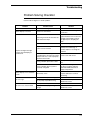
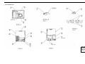
1
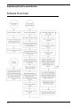
Ambulatory Blood Pressure Monitor 90217 Service Manual 070-0502-00 Rev. E Copyright 2003 Datex-Ohmeda, Inc. All rights reserved. Contents of this publication may not be reproduced in any form without the written permission of Datex-Ohmeda, Inc. Products of Spacelabs Medical, a Division of Instrumentarium, Datex-Ohmeda, Inc. (“Spacelabs Medical”) are covered by U.S. and foreign patents and/or pending patents. Printed in U.S.A. Specifications and price change privileges are reserved. Spacelabs Medical considers itself responsible for the effects on safety, reliability and performance of the equipment only if: • • • assembly operations, re-adjustments, modifications or repairs are carried out by persons authorized by Spacelabs Medical, and the electrical installation of the relevant room complies with the requirements of the standard in force, and the equipment is used in accordance with the operations manual. Spacelabs Medical will make available, on request, such circuit diagrams, component part lists, descriptions, calibration instructions or other information which will assist appropriately qualified technical personnel to repair those parts of the equipment which are classified by Spacelabs Medical as field repairable. Spacelabs Medical is committed to providing comprehensive customer support beginning with your initial inquiry through purchase, training, and service for the life of your Spacelabs Medical equipment. CORPORATE OFFICES U.S.A. CHINA ITALY Spacelabs Medical 5150 220th Ave SE Issaquah, WA 98029 Telephone: 425-657-7200 Telephone: 800-345-2700 Fax: 425-657-7212 Datex-Ohmeda Pte Ltd Shanghai Representative Office Room 2509 Lippo Plaza No. 222 Huaihai Road (M) Shanghai 200021 Telephone: 86-21-5382-5657 Fax: 86-21-5382-1691 Datex-Ohmeda S.p.A. Via Cassanese, 100 20090 Segrate (MI) Telephone: 39-02-216-931 Fax: 39-02-2692-6226 FRANCE Datex-Ohmeda SL Manuel Tovar, 26 28034 Madrid Telephone: 34-91-3342600 Fax: 34-91-3581284 AUSTRALIA Datex-Ohmeda Pty Ltd Unit 1, 149 Arthur Street Locked Bag 356 Homebush, NSW 2140 Telephone: 61-2-9735-7222 Fax: 61-2-9764-2354 AUSTRIA & BELGIUM Meda n.v. Oeyvaersbosch 12 B-2630 Aartselaar Belgium Telephone: 32-3-870-1111 Fax: 32-3-870-1112 Spacelabs Medical ZAC de Sans-Souci 1211 Chemin de la Bruyére 69760 Limonest Telephone: 33 4 78 666 210 Fax: 33 4 78 432 658 GERMANY Datex-Ohmeda GmbH Dr. -Alfred-Herrhausen-Allee 24 D-47228 Duisburg Telephone: 49-2065-691-0 Fax: 49-2065-691-236 CANADA HONG KONG Datex-Ohmeda Inc. 1093 Meyerside Drive, Unit 2 Mississauga, Ontario L5T 1J6 Telephone: 905-565-8572 Fax: 905-565-8592 Spacelabs Medical Limited Suite 901 Tower 1 China Hong Kong City 33 Canton Road, Tsimshatsui Kowloon Telephone: 852-2376-1370 Fax: 852-2376-2502 INDIA Datex-Ohmeda India Pvt. Ltd. International Trade Tower S 3 Level, Block E Nehru Place New Delhi 110019 Telephone: 91-11-621-6060 Fax: 91-11-621-3003 SPAIN TAIWAN Datex-Ohmeda Pte Ltd Taiwan Representative Office 2/FI No. 85 Sec. 2 Chien-Kuo N. RD. Telephone: 8862-2515-0457 Fax: 8862-2501-9136 THE NETHERLANDS Datex-Ohmeda B.V. De Wel 18 3871 MV Hoevelaken Telephone: 31-33-25-41-222 Fax: 31-33-25-41-223 Authorized EC Representative UNITED KINGDOM Datex-Ohmeda Ltd 71 Great North Road, Hatfield Herts AL9 5EN Telephone: 44-1707-263-570 Fax: 44-1707-260-065 CAUTION: • US Federal law restricts the devices documented herein to sale by, or on the order of, a physician. Contents Chapter Page Introduction Overview . . . . . . . . . . . . . . . . . . . . . . . . . . . . . . . . . . . . . . . . . . . . . . . . . . . . . . . . . . . . . . . . 1-1 User Controls . . . . . . . . . . . . . . . . . . . . . . . . . . . . . . . . . . . . . . . . . . . . . . . . . . . . . . . . . . . . 1-2 Display. . . . . . . . . . . . . . . . . . . . . . . . . . . . . . . . . . . . . . . . . . . . . . . . . . . . . . . . . . . . . . . . . . 1-2 Programming Options . . . . . . . . . . . . . . . . . . . . . . . . . . . . . . . . . . . . . . . . . . . . . . . . . . . . . .1-3 Setup Installing the Batteries . . . . . . . . . . . . . . . . . . . . . . . . . . . . . . . . . . . . . . . . . . . . . . . . . . . . . .2-1 Initializing the Monitor . . . . . . . . . . . . . . . . . . . . . . . . . . . . . . . . . . . . . . . . . . . . . . . . . . . . . . 2-2 Operational Tests . . . . . . . . . . . . . . . . . . . . . . . . . . . . . . . . . . . . . . . . . . . . . . . . . . . . . . . . . 2-7 Theory Pressure Amplifier . . . . . . . . . . . . . . . . . . . . . . . . . . . . . . . . . . . . . . . . . . . . . . . . . . . . . . . . . 3-1 Oscillometric Amplifier . . . . . . . . . . . . . . . . . . . . . . . . . . . . . . . . . . . . . . . . . . . . . . . . . . . . . .3-2 90217 Block Diagram . . . . . . . . . . . . . . . . . . . . . . . . . . . . . . . . . . . . . . . . . . . . . . . . . . . . . . 3-4 Digital Circuitry . . . . . . . . . . . . . . . . . . . . . . . . . . . . . . . . . . . . . . . . . . . . . . . . . . . . . . . . . . .3-5 Unit Power . . . . . . . . . . . . . . . . . . . . . . . . . . . . . . . . . . . . . . . . . . . . . . . . . . . . . . . . . . . . . . . 3-6 Software Flow Chart . . . . . . . . . . . . . . . . . . . . . . . . . . . . . . . . . . . . . . . . . . . . . . . . . . . . . . . 3-8 Maintenance Cleaning . . . . . . . . . . . . . . . . . . . . . . . . . . . . . . . . . . . . . . . . . . . . . . . . . . . . . . . . . . . . . . . . 4-1 Calibration Check . . . . . . . . . . . . . . . . . . . . . . . . . . . . . . . . . . . . . . . . . . . . . . . . . . . . . . . . . 4-3 Calibration Procedures . . . . . . . . . . . . . . . . . . . . . . . . . . . . . . . . . . . . . . . . . . . . . . . . . . . . . 4-4 Operational Verification . . . . . . . . . . . . . . . . . . . . . . . . . . . . . . . . . . . . . . . . . . . . . . . . . . . . 4-10 Manifold Kit - P/N 050-0110-00 . . . . . . . . . . . . . . . . . . . . . . . . . . . . . . . . . . . . . . . . . . . . . . 4-13 Disassembly Procedures. . . . . . . . . . . . . . . . . . . . . . . . . . . . . . . . . . . . . . . . . . . . . . . . . . . 4-14 Troubleshooting Monitor Event Codes. . . . . . . . . . . . . . . . . . . . . . . . . . . . . . . . . . . . . . . . . . . . . . . . . . . . . . . 5-1 Base Station Report Event Codes. . . . . . . . . . . . . . . . . . . . . . . . . . . . . . . . . . . . . . . . . . . . . 5-3 Problem Solving Checklist. . . . . . . . . . . . . . . . . . . . . . . . . . . . . . . . . . . . . . . . . . . . . . . . . . .5-5 Parts 90217 Field Replaceable Parts Lists . . . . . . . . . . . . . . . . . . . . . . . . . . . . . . . . . . . . . . . . . . . 6-1 Drawings . . . . . . . . . . . . . . . . . . . . . . . . . . . . . . . . . . . . . . . . . . . . . . . . . . . . . . . . . . . . . . . . 6-3 Symbols i Introduction Contents Overview. . . . . . . . . . . . . . . . . . . . . . . . . . . . . . . . . . . . . . . . . . . . . . . . . . . . . . . . . . . . . . . . . . . . . . User Controls . . . . . . . . . . . . . . . . . . . . . . . . . . . . . . . . . . . . . . . . . . . . . . . . . . . . . . . . . . . . . . . . . . Display . . . . . . . . . . . . . . . . . . . . . . . . . . . . . . . . . . . . . . . . . . . . . . . . . . . . . . . . . . . . . . . . . . . . . . . Programming Options. . . . . . . . . . . . . . . . . . . . . . . . . . . . . . . . . . . . . . . . . . . . . . . . . . . . . . . . . . . . 1 2 2 3 Overview The Model 90217 is a small, lightweight battery-powered Ambulatory Blood Pressure (ABP) monitor that uses the non-invasive Oscillometric method to measure blood pressure and heart rate. This data is then stored into memory for later transfer to an ABP Analysis System (FT1000A/FT2000A or equivalent), a PC Interface, a Base Station, or a Report Generator for data analysis, report printing, and archiving. The 90217 monitor is housed in a plastic case with a removable battery cover that provides access to its three AA cells. Inside the monitor are three printed circuit boards: the Main, Power, and Display boards. Programming resides in an internal 128k RAM and Microprocessor ROM. Most of the code exists in the RAM and can be updated via an infrared (IR) serial port located at the rear of the unit. The internal ROM contains a boot code and other codes for downloading and completing special tasks. The IR serial port transfers collected data to a report generator and sends setup changes to the ABP monitor. A rechargeable lithium battery keeps the RAM and real-time clock backed up during periods when the AA batteries are removed. 1-1 Ambulatory Blood Pressure Monitor User Controls The 90217 ABP monitor provides two user controls: a START/STOP button and Power ON/OFF switch. Power ON/OFF Switch When turned ON, this switch activates the monitor and begins executing the timed blood pressure program. START/STOP Button This front panel control manually starts a blood pressure measurement, stops a measurement already in progress, or sets special modes of operation (refer to the 90207, 90217 Ambulatory Blood Pressure Monitors Operations Manual, P/N 070-0137-xx). Display The monitor display is a 4-digit LCD that presents the following information (refer to the 90217 Ambulatory Blood Pressure Monitors, Operations Manual (P/N 070-0137-xx) for instructions on use). Systolic/Diastolic Pressure and Heart Rate Patient information appears on the display sequentially with systolic first, diastolic next, and then heart rate. Each parameter appears for approximately one second. The screen is blanked for one second and the sequence of readings is re-displayed two more times. A bar indicator at the left of the display identifies which parameter is currently being displayed. It appears next to the “sys” for systolic, next to “dia” for diastolic pressure, and next to the heart symbol for heart rate. Time of Day A real-time clock provides the time of day, which appears between measurement cycles and can be programmed in either a 12- or 24-hour mode. 1-2 Introduction Cuff Pressure This pressure can be shown while the monitor is taking a measurement. If cuff pressure is not selected, “----” appears. Cuff pressure can be enabled or disabled in software. Event Code Event codes are 4-digit LCD messages that begin with “EC” or, in some cases, show specific codes such as “LLL” for a low battery. If enabled, a beep sounds during an event code and the code is displayed on the monitor. Refer Troubleshooting on page 5-1 for event code information. Count Down Sequence Whenever the monitor begins a measurement cycle, it turns its tone ON (if beep is enabled) and counts down from 5555 to 1111 on the display. IR Communications During IR communications, the monitor first displays “9999” on the LCD to indicate that it has detected a cable connect and has gone into the communication mode. The monitor periodically attempts to contact a modem. The left two digits on the monitor display indicate the steps in the communication process. For more information, refer to Base Station via Modem on page 2-3. Programming Options These monitor options are user programmed: Day or Night Modes Day mode = beeper ON, inflation time approximately 15 seconds Night mode = beeper OFF, inflation time approximately 20 seconds Measurement Intervals and Periods Measurement intervals are selectable from 6 to 120 minutes (in one minute increments) for each period. It is also possible to not have readings taken during a specified period. Up to 12 periods may be defined. Clinical Verification Mode When set to this mode, the monitor is forced to bleed to 40 mmHg or to one step below diastole (whichever is lower) for each reading. Office Check Mode This mode verifies monitor operation and allows a user to view cuff pressure and blood pressure results regardless of any previous disabling of the display. During Office Check Mode, the monitor bleeds an additional pressure step below diastole. 1-3 Ambulatory Blood Pressure Monitor This mode is enabled for the first five successful blood pressure readings (or attempted readings) following monitor initialization. Office Check can be disabled by a patient cancel and can be reenabled after turning the power switch ON and holding the START/STOP button in while the last digit of the software version number is being displayed. Blood Pressure/Heart Rate Measurements Displayed These measurements can be selected to appear or not to appear at the end of a measurement. Cuff Pressure Displayed This measurement can be selected to appear or not to appear during the measurement cycle. 1-4 Setup Contents Installing the Batteries . . . . . . . . . . . . . . . . . . . . . . . . . . . . . . . . . . . . . . . . . . . . . . . . . . . . . . . . . . . 1 Initializing the Monitor . . . . . . . . . . . . . . . . . . . . . . . . . . . . . . . . . . . . . . . . . . . . . . . . . . . . . . . . . . . . 2 Operational Tests . . . . . . . . . . . . . . . . . . . . . . . . . . . . . . . . . . . . . . . . . . . . . . . . . . . . . . . . . . . . . . . 7 Installing the Batteries Two types of batteries are used in the 90217 ABP Monitor: three standard AA batteries (Spacelabs Medical P/N 146-5011-xx) to power the cuff air pump, and one rechargeable lithium battery to backup the clock and RAM circuits when the AA batteries are removed or are exhausted. This lithium battery receives its charge from the AA batteries and does not normally require replacement. Its expected life is at least nine years. If alkaline batteries are used as the AA batteries, they must be replaced after each patient use. Nickel cadmium batteries require a full charge before each use. AA Batteries To replace the three AA batteries: 1. Switch the monitor’s power switch to OFF. 2. Remove the battery compartment cover plate by sliding it to the right until it can be pulled free. 2-1 Ambulatory Blood Pressure Monitor 3. 3. If present, remove the old AA batteries from the monitor and replace each with a fresh alkaline battery (or fully charged nickel cadmium), being careful to match polarities where indicated (+ or -). ! • The monitor will not operate if batteries are incorrectly installed. • If the monitor is going to be stored longer than two weeks, remove the AA batteries to prevent the possibility of leakage or discharge. Spacelabs Medical is not responsible for product damage caused by battery leakage. If your unit has been damaged by a leaky battery, contact the battery manufacturer for any recoverable repair costs. 4. After correctly inserting the batteries, gently slide the battery cover back into place. 5. Switch the monitor ON and verify that the display appears. If there is no display, switch the monitor OFF and refer to the Troubleshooting chapter in this manual. When power is first switched ON, the first four digits of the RAM code revision are displayed for about 1 second, followed by a blanked display, followed by the last two digits of the revision number. Initializing the Monitor The ABP monitor must be initialized prior to use. Initialization specifies the monitoring period, patient information, time format, measurement interval, monitor tone ON/OFF during selected periods, event code display, and whether or not to display pressure values. To initialize the monitor, connect it to one of the following analysis systems. Local Report Generator For a direct connection to a Local Report Generator, place the monitor into the chute on the Report Generator (Model 90239A or equivalent): Local Report Generator Direct Connect Configuration Model 90217 Ensure that the monitor lines up against the side to align IR ports Local Report Generator (90239A) 2-2 Setup PC Interface For a direct connection to an IBM XT/AT/PS2 (or equivalent) via a Model 90219-02/90219-03 (or equivalent): 1. Connect the ABP monitor to the 90219 Analysis System. 2. Connect the 90219 Analysis System cable from the monitor to the serial port on the PC: PC Interface Direct Connect Configuration Model 90219 Analysis System 90217 ABP Monitor cable to serial port 3. Refer to the 90219 Ambulatory Blood Pressure PC Interface/Base Station Operations Manual (P/N 070-0238-xx) for instructions for operating the Analysis System. Base Station via Modem For a modem connection to a remote IBM XT/AT/PS2 (or equivalent) base station: Modem Connection Configuration TO BASE STATION MODEM PUBLIC TELEPHONE NETWORK cable to serial port ABP Monitor MODEM PHONE ! 1. • The initialization procedure is provided in the 90219 Ambulatory Blood Pressure PC Direct/Base Station Operations Manual (P/N 070-0238-xx). The 90217 can use one of the following modems for communication: • Hayes Smartmodem 1200 • Hayes Optima 9600 or equivalent • Most 2400 baud modems If the remote site also has 90202 or 90207 monitors, a Hayes Smartmodem 1200 must be used with those monitors. 2-3 Ambulatory Blood Pressure Monitor High Speed modems are setup via software commands. The Hayes Smartmodem 1200 which attaches to the monitor must be setup as follows: 2. ! Switch # Setting at Monitor Site 1 down 2 up 3 down 4 down 5 down 6 up 7 up 8 down 9 up 10 up Connect the serial port cable (P/N 012-0096-00) between the monitor and the modem. • If call waiting or call forwarding are options on the telephone used to transfer data, ensure that both are deactivated or modem communications may be interrupted. In addition, telephone systems such as CBX or PBX can cause interference with the modem, or the modem can cause interference with the switching system. To initialize the monitor for a remote connection: 1. Contact the base station by telephone (for remote operation only). 2. Ask the base station operator to initialize the monitor. Give the following information to the operator: • Patient's name. • Patient ID number. • If the monitor display is to be active or inactive. • Time of day (12- or 24-hour format). • If measurements are to be displayed (systolic/diastolic and heart rate). • Multiple or single cycle times. If using a single cycle for the 24-hour monitoring period, indicate the cycle interval and whether the tone is ON or OFF. For multiple cycle time, specify each cycle interval and whether the tone is ON or OFF for each cycle. • Any other information the base station operator may request. 3. The base station operator enters the patient information in the computer. 4. Prepare the monitor to receive the patient data from the base station. • Switch the modem ON. • When instructed by the base station operator, switch the ABP monitor ON. ! 2-4 • The modem link must be established within 45 seconds for the 90217. If this does not happen, switch the monitor OFF and return to step 1. Setup 5. When the information transfer is complete, the ABP monitor beeps and voice communication is restored. • Switch the monitor OFF and disconnect it from the modem. • If there is a direct connection between the monitor and the base station, switch the monitor OFF and disconnect it from the ABP data interface unit. To transfer readings from the monitor to the base station: 1. Contact the base station by telephone (for remote operation only). 2. Ask the base station operator to read the monitor. Give the following information to the operator: • Patient's name. • Patient ID number. • Any other information that the base station operator may request. 3. The base station operator enters the patient information into the computer. (If the monitor is in a remote location, the operator must turn power to the base station modem ON.) 4. Prepare the monitor to transfer data to the base station. • Switch the modem ON. • When instructed by the base station operator, switch the ABP monitor ON (for remote operation only). ! 5. • The modem link must be established within 45 seconds for the 90217. If this does not happen, switch the monitor OFF and return to step 1. When the information transfer is complete, the ABP monitor beeps and voice communication is restored. • Switch the monitor OFF and disconnect it from the modem. Modem Indicator Lights When the monitor is switched ON, the modem’s RD (receive data) and SD (send data) lights flash for several seconds. The OH (on hook) indicator is lit when the monitor starts communicating with the remote modem. When both modems connect, the CD (carrier detect) is lit. The SD and RD lights flash as data is being transferred. After the transmission is complete and the monitor is turned OFF, the HS, TR and MR indicators will always remain lit at the local modem. 2-5 Ambulatory Blood Pressure Monitor 90217 Modem Connection Status Indications The left-most digit of the 90217 display shows the various stages of the modem connection process: 1 Sending modem identify query. 2 Waiting for response to identify query. 3 Sending modem reset commands. 4 Sending modem setup commands. 5 Send off-hook command. 6 Waiting for contact. 7 Contact established. 9 Not attempting to contact modem. Once contact has been established, the second digit from the left on the 90217 display indicates the baud rate of the connection. On high speed modems, the indicated speed refers to the connection between the ABP monitor and the modem. The two modems may be communicating at some speed other than that at which the modem is communicating with the monitor. The baud rate codes are as follows: 0 1200 1 not used 2 2400 3 4800 4 9600 5 19.2 k 6 38.4 k Setup Test ! • Verify that all cable connections are installed correctly and are connected securely. Switch the ABP monitor ON. It initially displays “9999”. When the monitor is being read or initialized, these digits change to indicate that communication is taking place between the monitor and the analysis system. When communication is complete, the digits stop changing. The right-most digit indicates that a message has been sent from the monitor to the base station. The second digit from the right indicates that a non-garbled message has been received by the monitor. A common failure mode is with only the right digit spinning. This indicates garbled messages are being received and an “I don’t understand” response is being transmitted by the monitor. 2-6 Setup Operational Tests Conduct the following procedures to verify proper operation of the Model 90217 ABP Monitor. Equipment Required • • • • • • • • 90219-02 system 90219-03 ABP Base Station software Type AA alkaline batteries (3) Cable, 90217 to PC, P/N 012-0097-xx (greater than -02) Setup for air leaks (see Air Leak Test for illustration) Analog manometer (optional) Stop watch or equivalent Battery spring insertion tool, P/N 003-0084-00 Visual Inspection 1. Check the display window and ensure that it is clear (free from scratches, contamination, etc.) with the words “SYS DIA” appearing on the left side. 2. Verify that the front panel START/STOP button responds with a clear “snap” when depressed. 3. Inspect inside the battery compartment to ensure that the battery springs are clean and provide a good electrical contact with the batteries. 4. Install the three AA batteries and verify that the battery door closes and latches properly. Air Leak Test 1. ! Connect the test setup illustrated below: • This figure shows the use of both an analog and digital manometer. Both or either can be used in these tests. If only one manometer is used, block off the unused hose. 2-7 Ambulatory Blood Pressure Monitor 2. Close the squeeze bulb valve. 3. Turn the 90217 ON and press the START/STOP button. 4. Verify the following monitor response: • Two beeps are sounded. • The display counts down: 5555, 4444, 3333, 2222, 1111. • Pumping begins and “_ _ _ _” is displayed (could display the pump pressure, depending upon how the monitor was initialized). 5. ! Verify that the system pumps up to 165 mmHg, +/- 8 mmHg, before the pressure begins to drop in 7 to 9 mmHg steps. Ensure that the pressure does not drift down. • It may take 3 or 4 steps before the cuff size is learned by the monitor and the steps fall within this range. 6. Verify that the display reads “EC18”. 7. Open the bulb valve and remove the monitor from the manometer setup. PC Interface Test 1. Connect the system as illustrated: 2. Power ON all devices. 3. Start the 90219-03 Base Station software (loaded on hard drive). 4. Type: ABP (or ABPPCI) and press the Enter key on the base station. ! 2-8 • If the file name has been changed from ABP, type DIR and press Return to determine the new name. Setup 5. Switch the 90217 power switch ON. 6. Press in this order: Space Bar 1 (ABP communication) 3 (direct connect - skip this step if a PC Interface data key is attached instead of a base station data key) 2 (read ABP unit) 7. Press any key (wait). 8. Type 8, Enter key, and Y (yes). ! 9. • “8” is the name of a dummy file which should be setup on the computer already. Press the END key. 10. Verify that the clinical data appears on the computer screen. The last reading on this screen is the results of the test done earlier in these procedures. 11. Verify that the date and time are correct and that the event code “EC18” appears. 12. Press the ESC key. 13. Initialize the 90217 by typing: 1 (initialize ABP) 14. Press the END key and use the up arrow key until PATIENT NAME is selected. 15. Type: TEST and press the Enter key 1234567890 and press the Enter key NONE and press the END key 16. Verify that the display reads “***MONITOR INITIALIZED***”. 17. Press: Space Bar ESC key ESC key ESC key Y key (yes) 18. Remove the 90217 from the system and switch power OFF. 19. Remove one AA battery. 20. Wait one minute and reinstall the battery. 21. Switch 90217 power ON and verify that the time remained correct. 2-9 Theory Contents Pressure Amplifier . . . . . . . . . . . . . . . . . . . . . . . . . . . . . . . . . . . . . . . . . . . . . . . . . . . . . . . . . . . . . . Oscillometric Amplifier . . . . . . . . . . . . . . . . . . . . . . . . . . . . . . . . . . . . . . . . . . . . . . . . . . . . . . . . . . . 90217 Block Diagram . . . . . . . . . . . . . . . . . . . . . . . . . . . . . . . . . . . . . . . . . . . . . . . . . . . . . . . . . . . . Digital Circuitry . . . . . . . . . . . . . . . . . . . . . . . . . . . . . . . . . . . . . . . . . . . . . . . . . . . . . . . . . . . . . . . . . Unit Power . . . . . . . . . . . . . . . . . . . . . . . . . . . . . . . . . . . . . . . . . . . . . . . . . . . . . . . . . . . . . . . . . . . . Software Flow Chart . . . . . . . . . . . . . . . . . . . . . . . . . . . . . . . . . . . . . . . . . . . . . . . . . . . . . . . . . . . . . 1 2 4 5 6 8 Pressure Amplifier The pressure amplifier monitors the voltage produced across the pressure transducer. This voltage is proportional to the pressure in the arm cuff. The pressure transducer circuits require temperature compensation to account for changes in sensitivity. This is accomplished by using a reference current to provide a constant current source into the bridge. Any change in bridge resistance due to temperature will change the bridge voltage in an amount that compensates for any change in sensitivity. Voltage across the transducer is amplified differentially and turned into a single ended voltage that is amplified, offset and sent to the processor’s A/D converter, the oscillometric amplifier and the overpressure detector. Offset Adjust Both transducer offset and operational amplifier offset are nulled out using a pressure offset adjustment. Minor variations in the offset are tracked and compensated for in software. Gain Adjust Changes in gain are compensated for with a gain adjustment. The voltage gain to the A/D converter is +15 mv/mmHg, and the voltage is offset by approximately 0.09 volts. This 0.09 volts is inserted to prevent the A/D converter signal from going negative during drifts in the offsets. The 0.09 volt offset is subtracted in software. 3-1 Ambulatory Blood Pressure Monitor Oscillometric Amplifier Gain, Offset and Filtering The oscillometric amplifier is DC coupled. A D/A convertor provides large amounts of DC offset to the amplifier to prevent the large static pressure component of the waveform from over driving the amplifier. It provides gain (x64), DC offset, and high frequency filtering (3dB point = approximately 80 Hz). The oscillometric filtering that was present in earlier designs is now done by software. RAM Protect and Reset Circuit When the +5 volt power supply begins to drop, the RAM protect circuit asserts a reset signal to the processor that protects RAM data during power collapse. This same circuit provides a start up processor reset signal at power up. Reset time is a product of the reset R-C time constant and the hold off time necessary for the power convertor to reach +5 volts (the reset time constant is 350 msec). A/D Voltage References The A/D reference (+ADR) is generated from a LM4041-1.2 band gap reference. Its reference output of 1.2 volts is amplified to 4.608V by a gain adjustable amplifier (+ADR = +4.608 volts, adjustable). 30 Second Pulse The real-time clock produces a pulse every minute with a 30 second duration. This pulse’s leading and trailing edges are conditioned into separate pulses and applied through a diode to the processor’s WAKE_UP line to awaken it every 30 seconds. Second Pulse The SECONDS line goes to the LCD where it blinks the colon and changes the LCD polarity. Cable Connected If a cable is connected to the RS-232 communications connector with the power switch ON, the power converter activates and awakens the processor. A cable connected condition prevents the power converter from going down as a result of a shutdown fault generated by the watch dog timer, but cannot prevent an over-pressure shutdown. Once a cable has been connected, the processor goes into a listening mode, awaiting instructions from the RS-232 port. These instructions adhere to the ABP communications protocol. 3-2 Theory Watch Dog Timers The watch dog timers ensure that the cuff cannot remain inflated because of a software crash. There are two watch dog timers in the Model 90217: one resides inside the processor; the other inside the real-time clock. Each counts 180 seconds before timing out. Both timers start at converter power up. The real-time clock watch dog timer triggers the hold off that disables the pump, opens the bleed valve, and informs the CPU of its action. In 16 seconds after the hold off is asserted (if the software does not end the reading) fault shutdown resets the system. The hold off is also asserted at the end of every reading. The hold off always stays active for 32 seconds or until a manual reading is started. Fault Shutdown The fault shutdown circuitry resets the system because of two conditions: • There is an over-pressure condition not detected by software. • Pressure reading takes longer than 180 seconds (this indicates a software crash since a software time out should have already stopped the reading). Over-Pressure Detector In addition to software over-pressure detection, there is also a hardware over-pressure detector that activates at approximately <295 mmHg. A one-half second delay in initiating an over-pressure response prevents motion artifacts from causing a false over-pressure detection. 3-3 Ambulatory Blood Pressure Monitor 90217 Block Diagram 3-4 Theory Digital Circuitry Display Board Information is sent from the processor to the LCD controller via a serial bus (CBUS). The LCD controller activates the necessary segments to display information on the 4-segment LCD. Each of the segments can be controlled separately. The processor determines which segments must be turned ON and sends this information to the controller. An exclusive OR gate blinks the colons once per second when in the clock mode and also changes drive polarity. Real-Time Clock The real-time clock sends and receives data via a bidirectional serial bus that goes to the processor. The clock is backed up by the 3 volt lithium cell when the main batteries are removed. The clock uses an adjustable 32 KHz crystal. RAM A 128K x 8 RAM stores patient collected information, programmed information, and RAM code software execution. RAM is backed up by the 3 volt lithium cell during main battery removal. Addressing and Control Addressing and control are accomplished using a combination of processor ports, latches, and gates. Communications RS-232 Connector The communications connector is a modified RS-232 interface. When the communications cable (IR cable) is connected to the back of the unit, a reed relay activates the monitor if the power switch is turned ON. At this point, the processor checks and determines that the C_CON cable connected line is asserted and goes into the communication mode. The processor determines whether the cable is communicating with a modem or a report generator and responds accordingly. Communications are done using two lines: transmit and receive. Data is converted into IR signals in the cable and ABP monitor. Processor The processor type is an 80C198 with a 7.37 MHz crystal. It contains on-board RAM, ROM, A/D converter, data ports, addressing control, serial bus lines, and modulator ports that control motor speed and speaker outputs. The on-board ROM contains routines for communication and start up. The majority of the ABP monitor’s program is loaded into RAM using the infrared RS-232 port. 3-5 Ambulatory Blood Pressure Monitor Unit Power All power for the Model 90217 ABP Monitor comes from the main batteries (3 AA cells) and the rechargeable 3 volt lithium battery. Unregulated Power Supplies +VSW The switched battery voltage (+VSW) is provided by the main batteries via the unit power switch. With this switch ON, +VSW is applied to the power converter, the air pump, and to the various circuits which must remain active during the processor idle down mode. +VBB The backup battery supply (+VBB) is always a diode drop (0.3 volts) down from the main battery voltage (+VSW), the +5, or the lithium battery voltage, whichever is the highest. • If the power switch is OFF and there are charged main batteries in the unit, the main batteries supply the voltage through a diode (+VBB will be approximately 3.3 to 4.5 V). • If the power switch is ON and the +5V supply is higher than +VSW, the power comes from the +5V supply through a diode (+VBB is approximately 4.6 to 4.8 V). • If the main batteries are removed, the voltage is developed from the lithium backup battery through a diode (+VBB is approximately 3.0 V). Power Converter The power converter is a MAXIM “MAX655” step-up converter. It develops the +5 V supply from the main battery voltage which ranges from 2.5 to 4.8 VDC. Low and High Current Modes When the power converter is in its low current mode, it draws 40 ∝amps of quiescent current. The power converter goes into a high current mode upon receiving an interrupt from any of its three wake-up sources: cable connect, clock, or START/STOP button. A 5 msec delay following a wakeup signal keeps the power converter in high current mode while the processor wakes up and asserts the PWR_HI line. The power convertor develops the +5 V supply, the +5 VA supply, and the converter reference voltage, ONNV_VREF. +5 V Supply The +5 V supply is developed directly from the +VSW (main batteries and is regulated to +4.75 to +5.25 volts). The maximum current available is 60 ma (typical draw is approximately 20 ma). +5 VA Supply +5 VA is a secondary power source for the analog circuitry. It can be disconnected to reduce power consumption when the analog circuits are not being used by asserting the PWR_DWN line. 3-6 Theory CONV_VREF The converter reference (CONV_VREF) is created by a band gap reference (about 1.25 volts) to produce +5 volts (adjusted to + 5 volts) at the +5 VA supply. Backup Battery Circuit A 3.0 V rechargeable lithium cell provides backup power to the clock and RAM circuits when the main batteries are removed or exhausted. This lithium battery receives its charge from the three AA batteries and has a 20 - 35 ma/hrs capacity with sufficient charge to last approximately 4 months without the main batteries installed. Main Battery The main battery voltage is monitored by reading the BAT VOLTS line with the A/D converter. The voltage at this point is a divided down sample of the +VSW voltage. Wake-up Interrupt The power converter is activated when one of its three wake-up sources generate an interrupt and trips the 5 msec one-shot. The microprocessor must assert the PWR_HI line during this 5 msec period to place the power converter in its high power mode. Three sources can place the power converter into high power mode: • An RS-232 serial cable is connected This cable connect is detected when the reed switch is activated by an external magnet. When the reed switch closes, it causes an interrupt to the processor on the WAKE_UP line. • A clock wake-up The real-time clock produces an output that changes state every 30 seconds. These transitional states are shaped into pulses that create interrupts to the processor. • The START/STOP button is pressed When the START/STOP button is pressed, the WAKE_UP line is asserted Once an interrupt request has gone to the processor by asserting the WAKE_UP line, the processor looks to see which of the three sources asserted the WAKE_UP line. Power Switch When the power switch is ON (closed), the +VSW supply comes up and provides power to all the circuitry in the ABP unit. The +VBB supply receives power directly from the main batteries to ensure that the lithium battery will not be drained when main batteries are available. 3-7 Ambulatory Blood Pressure Monitor Software Flow Chart 3-8 Maintenance Contents Cleaning . . . . . . . . . . . . . . . . . . . . . . . . . . . . . . . . . . . . . . . . . . . . . . . . . . . . . . . . . . . . . . . . . . . . . . 1 Calibration Check . . . . . . . . . . . . . . . . . . . . . . . . . . . . . . . . . . . . . . . . . . . . . . . . . . . . . . . . . . . . . . . 3 Calibration Procedures . . . . . . . . . . . . . . . . . . . . . . . . . . . . . . . . . . . . . . . . . . . . . . . . . . . . . . . . . . . 4 Operational Verification . . . . . . . . . . . . . . . . . . . . . . . . . . . . . . . . . . . . . . . . . . . . . . . . . . . . . . . . . 10 Manifold Kit - P/N 050-0110-00 . . . . . . . . . . . . . . . . . . . . . . . . . . . . . . . . . . . . . . . . . . . . . . . . . . . 13 Disassembly Procedures . . . . . . . . . . . . . . . . . . . . . . . . . . . . . . . . . . . . . . . . . . . . . . . . . . . . . . . . 14 Periodic maintenance consists of cleaning the unit, replacing or recharging the batteries, testing the unit for accurate operation, and calibrating when necessary. Cleaning Use a soft, damp cloth and mild detergent mixed with water to wipe the exterior of the monitor. Clean the carrying pouch and air hose with isopropyl alcohol. The cuff wrap may be sterilized only with ethylene oxide (ETO) sterilization methods using standard hospital procedures. Use standard aeration techniques after sterilization. Small soiled or stained areas may be cleaned by gentle scrubbing with a sponge or cloth soaked in a mild soap and water solution. The cuff wrap with the air bladder removed is machine washable on “delicate” cycle only. Do not wash with bed linens, gowns, or in large commercial-type washers. To remove the bladder for cleaning, refer to the figures below and follow these steps: 1. Using your fingers only, fold or roll up the bladder inside the cuff. Do not use pencils, pens, or other hard objects as damage to the bladder could easily occur. 2. Remove the bladder through the hose exit opening. Once the bladder has been removed, be sure to attach the hook and loop surfaces on the cuff before washing. 3. After washing and drying the cuff, reinstall the bladder in the reverse order of its removal. Make certain that all folds in the bladder are removed prior to inserting it back inside the cuff. ! • The bladder may be installed with the hose exiting the second cuff opening. However, the bladder must be positioned with its long side toward the center of the cuff. 4-1 Ambulatory Blood Pressure Monitor Air Bladder Removal Air Bladder Reinstallation 4-2 Maintenance Calibration Check To verify calibration of the 90217 ABP Monitor: 1. Obtain a full-size mercury sphygmomanometer (manometer) or aneroid gauge. 2. Disconnect the cuff hose from the monitor. 3. Connect the T-tube (P/N 016-0040-00) to the monitor luer connector and the manometer: 4. Wrap and fasten the cuff around a rigid cylinder, such as a bottle, that is approximately 6 inches long (15.3 cm) and 3.5 inches (8.9) in diameter. 5. Press the START/STOP button on the front of the monitor. After the pump has stopped, the monitor display should read approximately 165 mmHg (only if the START/STOP button has been operated since the last measurement, otherwise it should read 35 mmHg above the average of the last five readings). Compare the readings on the monitor and the manometer while the pressure bleeds down. The monitor reading should be within three millimeters of the manometer reading or 2% of the reading, whichever is greater (+/- the accuracy of the manometer). At the end of this procedure, the monitor will display an event code. 6. Disconnect the T-tube from the monitor. Disconnect the air hose and sphygmomanometer from the T-tube. Re-connect the cuff to the monitor. 4-3 Ambulatory Blood Pressure Monitor Calibration Procedures The following procedures allow field testing and calibration of the Model 90217 ABP Monitor. Equipment Required • Computer system, 90219-02 compatible with appropriate software • DC voltmeter, 4.5 digits, Fluke 8060A or equivalent • Diskette, 90217, Production Test Aids (P/N 063-0609-xx) • Diskette, 90217 RAM code, current version • AA type batteries, 3 ea. • Cable, IR communications, 90217/90207 (P/N 012-0097-02 or later) • Calibration test setup (see page 4-5) • Screwdriver, 0.05” flat blade, insulated handle • Screwdriver, Phillips, #0 tip • Screwdriver, Phillips, #1 tip • Hemostats • Magnet Preparation • Carefully read through these procedures • Connect the communications cable to the IR port on the 90217 • Load the Production Test Aids software (Xmain.exe) onto the hard disk of the computer system • Copy the 90217 RAM code into same directory as Xmain.exe program (Production Test Aids software) • Ensure that charged batteries (3) are installed into the 90217 monitor ! • A voltmeter may be used to check battery condition. NiCads: 1.30 V = full charge (>1.25 V minimum) Alkaline: 1.56 V = full charge (> 1.50 V minimum) 4-4 Maintenance Pre-calibration Checks 1. Remove the back cover on the 90217 monitor. 2. Measure the +4.608 volt reference (TP7) on the Main Board. a. Place a magnet near the IR port on the monitor (or connect the IR cable to the port). b. Switch monitor power ON. c. Connect a DC voltmeter positive lead to TP7 (+4.608) and the negative lead to TP9 (ground). Refer to the figures below for test point locations. 4-5 Ambulatory Blood Pressure Monitor d. 3. 4. Verify that TP7 is between +4.605 and +4.611 volts. If not, readjust R22 to obtain +4.608 +/- 0.002 V. Measure the +5 V supply (TP6) on the Main Board. a. Connect a DC voltmeter with the positive test lead on TP6 (+5 volts) and the negative on TP9 (ground). b. Verify that TP6 measures between +5.05 and +4.95 volts. If not, adjust R78 on the power board until TP6 measures +5.0 +/- 0.01 volts. Replace the back cover of the 90217 case (removed in step 1). Calibration Setup 1. Verify that the IR cable is connected to the serial port on the computer system and to the IR port on the back of the 90217 (when communicating correctly, the monitor will display “9999” and occasionally “2999”). 2. Start the “X” program by changing to the subdirectory where the file XMAIN.exe is located and typing: X and pressing the Enter key. 3. When the computer establishes contact with the monitor, the Test Utility Main Menu appears: 1. SYSTEM CONFIGURATION 2. MAKE CONTACT WITH MONITOR. ENTER SELECTION__ From this menu, select MAKE CONTACT WITH MONITOR by typing the item number appearing to the left of this menu item (2) and pressing Enter. Verify that the screen clears and momentarily displays “SPEED 4 IS ENGAGED” (and other miscellaneous information). If the RAM code is corrupted, the program downloads code. 4-6 Maintenance 4. At the conclusion of the above process, the Manufacturing Test Utility Main Menu reappears with additional menu items and the monitor’s RAM and ROM code version numbers: 1. SYSTEM CONFIGURATION 2. INITIALIZE MONITOR. 3. DOWNLOAD 90217 RAM CODE. 4. EXHAUSTIVE MEMORY TEST. 5. SET 90217 GAIN AND OFFSET. 7. SPEAKER TEST. 8. PUMP TEST. 9. HARDWARE OVERPRESSURE TEST. 10. COMMUNICATIONS TEST. 11. MANOMETER MODE. 12. RESET FOR ANOTHER MONITOR. ENTER SELECTION __ ROM ID = 90217 V 03.02.xx RAM ID = 90217 V 03.02-xx 5. Select 2, INITIALIZE MONITOR. 6. Verify that the screen displays “ABP RESET SUCCESSFUL” and “CLOCK SUCCESSFULLY SET” and that the Main Menu screen again appears. Pressure Offset and Gain Adjustment 1. Adjust the pressure offset: a. From the Main Menu, select 5, SET 90217 GAIN AND OFFSET. b. Verify that the following screen appears: 90217 GAIN AND OFFSET ADJUSTMENT 1. Adjust offset pot for 00 with hose disconnected. 2. Adjust gain to match manometer at about 200 mmHg. 3. Due to interaction, repeat 1 and 2 as needed. 0.1 mmHg c. 20 counts Verify that the mmHg value appearing at the bottom of the screen reads 0.0 ±0.3. If not, readjust R49 (pressure offset adjustment) until the mmHg value at the bottom of the screen reads 0.0 ±0.1. 4-7 Ambulatory Blood Pressure Monitor 2. Adjust the pressure gain: a. Connect the sphygmomanometer test configuration to the 90217 monitor: b. Manually pump system pressure to 195 mmHg. c. Verify that the mmHg value appearing at the bottom of the screen reads 195 ±1.0. If not, adjust R42 (pressure gain adjustment) until the mmHg value reads 195. 3. Repeat the offset and gain adjustments until no further adjustments are required to produce the correct values. Pressure Leakage 4-8 1. In the sphygmomanometer test configuration, use a hemostat to clamp the hose going to the 90217 and pump the pressure to 280 mmHg ±4. 2. Clamp the hose going to the squeeze bulb with a hemostat and measure the leakage rate (system leakage). 3. Unclamp the hoses going to the 90217 and squeeze bulb. 4. Repump the system to 280 mmHg, reclamp the hose to the bulb and measure the leakage rate (90217 + system leakage). 5. Subtract the first leakage rate (system leakage) from the second leakage rate (90217 + system leakage). Maintenance 6. Verify that the pressure drop due to 90217 leakage is <6 mmHg per minute, or <4 mmHg per 4 minutes for 90217-41 (Japan) and <4 mmHg per 2 minutes for 90217-32 units (German). 7. Release the system pressure. Over-Pressure Checks 1. Press the Esc key (the main menu should return). 2. From the Main Menu, select 9, HARDWARE OVERPRESSURE TEST. 3. Verify that the pump starts and continues to run, building pressure until the hardware overpressure limit is achieved. Verify that the pressure value appearing at the bottom of the screen falls between 285 and 295 mmHg. 4. Press the Esc key. Over-Pressure Relief Valve Check 1. Power the 90217 OFF. 2. Disable the hardware over-pressure circuit by connecting TP8 (over-pressure test point) to TP9 (ground) using a small patch cable. 3. Power the 90217 ON. 4. From the initial menu, select 2, MAKE CONTACT WITH MONITOR. 5. When the Main Menu appears, select 9, HARDWARE OVERPRESSURE TEST. 6. The pressure will increase until it opens the over-pressure relief valve. When the pressure increase levels off at a rate of 3 sec/mmHg, check the pressure displayed on the manometer and verify that it falls between 300 and 325 mmHg. 7. Remove the jumper between TP8 and TP9. 8. Power the 90217 OFF. 9. Press the Esc key. 10. Power the 90217 ON. Hardware Safety Timers Check 1. From the main menu, select 2, MAKE CONTACT WITH MONITOR. 2. When the main menu appears, select 11, MANOMETER MODE. 3. Manually pump up the system pressure to 165 mmHg ±10. 4. Remove the IR cable and start the timer. 5. Exit the X program and return to DOS by pressing Esc two times. 6. When the valve opens (pressure decreases rapidly), verify that the elapsed time is between 178 and 182 seconds (fault holdoff timer). 7. When the 90217 display changes from showing pressure to showing the software version, verify that the elapsed time falls between 194 and 198 seconds (watch dog timer). 8. Remove the test setup and restore any 90217 screws previously removed. 4-9 Ambulatory Blood Pressure Monitor Operational Verification These procedures verify that the 90217 ABP monitor’s blood pressure readings are consistent with design standards. ! • These procedures use the DynaTech Nevada CuffLink Blood Pressure Simulator. If you are using a different simulator, refer to its operator’s manual and determine equivalent tests. Refer to the end of this Maintenance chapter for instructions on using the CuffLink simulator in the automatic or the manual mode. Equipment Required • DynaTech Nevada CuffLink Non-invasive Blood Pressure Analyzer (and equivalent) and associated tubing, manuals, luer fittings (software version 2.0 or higher is required) • 1/8” I. D. tubing (P/N 162-0019-00 or equivalent) • Adult cuff (P/N 016-0264-00 or equivalent) • Luer connector (P/N 103-0008-00) Blood Pressure Simulator Preparation 4-10 1. Turn the CuffLink simulator ON and allow it to warm up for a minimum of 15 minutes. 2. Verify that the calibration sticker is current. If it is not, the simulator will need to be calibrated by the manufacturer or its authorized service facility. 3. Check the zero pressure by selecting ADAMS Adult from SelectBp in the main menu. 4. Press ENT. 5. Press F5 to zero the pressure. 6. Press Esc to return to the main menu. 7. Perform a leak rate check on the blood pressure simulator and associated tubing as follows: a. While in the main menu, move the cursor to Press and select Leak Test by pressing ENT. b. Connect a squeeze bulb to the hose which will connect directly to the unit under test. c. Pump up the system pressure to approximately 170 mmHg. d. Wait 10 seconds for the pressure to stabilize. e. Press the START (F1) key on the CuffLink simulator and wait one minute while the leak rate is measured. f. At the end of the minute, the leak rate will appear on the CuffLink display. g. If the leak rate is greater than 10 mmHg/min, retighten all external hose connections and repeat the test. If the system continues to fail, isolate each length of tubing to locate and repair the source of the leak. h. Press the Esc key to return to the main menu. Maintenance 90217 Test Preparation 1. Setup the ABP monitor by connecting it to the CuffLink. 2. Refer to the table below for a list of systolic/diastolic/heart rate settings to be performed on the 90217 monitor: Pressure Setting Range 60 52-60 Diastolic 30 26-33 Heart Rate 40 Systolic 100 91-103 Diastolic 65 60-70 Heart Rate 60 Systolic 120 111-124 Diastolic 80 74-88 Heart Rate 80 Systolic 150 143-161 Diastolic 100 92-108 Heart Rate 120 Systolic 200 196-218 Diastolic 150 142-158 Heart Rate 120 Systolic 255 253-277 Diastolic 195 185-205 Heart Rate 120 Systolic 3. Connect the 90217 to the simulator: 4. Move the CuffLink cursor to SelectBp and press the ENT key to select ADAMS Adult. 4-11 Ambulatory Blood Pressure Monitor 5. Press the F2 key (AdjEnv) and verify that the gain is at 100%. If it is not, adjust it using the arrow keys. At the same time, verify that OFFSET and/or SHIFT are at 0. 6. Press the ENT key. 7. Press the Esc key to return to the main menu. 8. Move the cursor to AUTO using the arrow keys and select Execute using the ENT key. 9. Press the F1 key to select ADULT readings. 10. Zero the pressure by pressing the F5 key. 11. Press the Esc key until the first pressure simulation reading is displayed on the CuffLink. 12. Press the START/STOP button on the ABP monitor to start the reading. ! • The CuffLink simulator may automatically change to the next blood pressure setting when the current reading is complete. If you must repeat a reading, press the Esc key repeatedly until the ADULT INFANT menu is shown at the bottom of the screen. Press the F1 key to select ADULT readings and then use the Esc key to increment to the reading desired. 13. Repeatedly press the START/STOP button on the 90217 to sequence through the list of blood pressures simulated by the CuffLink. 14. At the end of the readings, verify that the systolic and diastolic readings are within given ranges provided in step #2. ! • If the readings are out of range, retest the ABP monitor at the same setting. If it still fails, check all hose connections, perform the leak test as described in the beginning of these procedures, and check the gain settings on the simulator. If all this fails, refer to Troubleshooting on page 5-1. CuffLink Manual Operation The following steps outline the manual selection of simulated blood pressures and heart rates. These may be used to repeat a reading which was out of range or produced no reading. 4-12 1. When the CuffLink is warmed up, move the cursor to the SelectBp option of the main menu and ADAMS Adult. Press the ENT key to make a selection. 2. Press the F2 key and verify that the gain is set to 100%. At the same time, verify that the SHIFT and/or OFFSET are at 0. Press the ENT key. 3. Press the F1 key to move to the heart rate menu. Use the arrow keys to move the cursor to the desired heart rate. Press the ENT key to make a selection. 4. Use the arrow keys to move the cursor to the desired blood pressure and press the ENT key. 5. The CuffLink is ready to simulate the selected heart rate and pressure. Press the START/STOP button on the monitor to begin. Maintenance CuffLink Automatic Operation Use the following procedure to set or change the automatic sequences stored in the CuffLink: 1. Move the cursor to the Auto option of the main menu and select Utility by pressing the ENT key. 2. Use the arrow keys to move the cursor to the EDIT box. Select sequences to edit and press the appropriate button (F1, F2, F3, etc.). F1 is assigned to ADULT. In the first screen, answer YES to the Pop-Off test and NO for the rest. The second and third screens list the sequence of blood pressures and heart rates. Use the arrow keys to move around the list and use the F4 and F5 keys to change the settings. Set CYCLES for each blood pressure reading. When finished making changes, press F3 (STORE) to end the edit session. 3. Use the arrow keys to move the cursor to the NAME box. Select the sequence to be named and press the appropriate button (F1, F2, F3, etc.). Use the arrow keys to move to each character and use the UP and DOWN arrow keys to change the character. When complete, press ENT to end the edit. Manifold Kit - P/N 050-0110-00 To replace the manifold in the 90217 monitor: 1. Disassemble the 90217 ABP Monitor and remove the 672-0171-xx assembly. Separate the manifold from the rest of the assembly by cutting through the 176-0279-00 four-conductor flexstrip cable. Refer to Disassembly Procedures on page 4-14. 2. Unsolder the remaining section of flexstrip from the 672-0171-xx assembly and clear the holes of solder. 3. From the back (non-display) side of the display board, insert the leads from the new flexstrip. They are pre-attached to the manifold and should fit into the cleared holes in the old assembly. Do not bend or stress the new flexstrip any more than necessary during replacement. 4. Ensure that the flexstrip is squarely aligned with the display board and fully seated. Solder the four leads in place and trim excess lead length. 5. Install the 672-0171-xx assembly back into the case. 6. Perform a full monitor calibration. Refer to Calibration Procedures on page 4-4. 7. Reassemble the 90217 monitor. 4-13 Ambulatory Blood Pressure Monitor Disassembly Procedures WARNING: • Never touch electrostatic-sensitive electronic components without following proper anti-static procedures, including the use of an ESD wrist band and mat. An electrostatic discharge from your fingers can permanently damage electronic components. • All static-sensitive electronic components are packaged in static-shielding bags. Retain this bag for repackaging the component should you need to store it or return it to Spacelabs Medical for any reason. To open the monitor and access its internal components: 1. Remove the Communications label from the back of the unit (refer to the Parts section of this manual for replacement part number) and remove the two screws that are exposed (see below). 2. Remove the identify label on top of the unit (see illustration below) and remove the two exposed screws to separate the top and bottom case pieces. To separate the ECB assembly from the bottom case half: 4-14 1. Remove the front panel label from the unit (refer to the Parts section of this manual for replacement part number) and expose the two screws holding the ECB assembly. 2. Remove these two screws (see previous illustration) and separate the ECB assembly from the lower half of the case. Troubleshooting Contents Monitor Event Codes . . . . . . . . . . . . . . . . . . . . . . . . . . . . . . . . . . . . . . . . . . . . . . . . . . . . . . . . . . . . 1 Base Station Report Event Codes . . . . . . . . . . . . . . . . . . . . . . . . . . . . . . . . . . . . . . . . . . . . . . . . . . 3 Problem Solving Checklist . . . . . . . . . . . . . . . . . . . . . . . . . . . . . . . . . . . . . . . . . . . . . . . . . . . . . . . . 5 If monitor problems develop use the information provided in this chapter as a problem solving guide. Monitor Event Codes The Model 90217 ABP Monitor displays a two-digit event code whenever it is unable to successfully complete a blood pressure measurement. This event code appears as the last digits on the monitor display and is preceded by the letters EC (for example, in the displayed event code EC01, 01 is the event code). The following list contains a brief description of event codes which can appear: EC03 Patient cancel. EC04 Out of time for measurement. NO time to collect additional data but enough time to evaluate data already collected. Evaluation did not produce a valid reading. EC05 Individual result corrupted. EC10 Hung 20 seconds at a bleed step. EC11 Did not pump high enough. Failed to inflate cuff above systole. EC13 Reset of Office Check mode. EC15 Bad checksum in ROM. EC16 Low battery detected before cuff measurement. EC18 Too few entries in table to perform analysis. EC20 Pulse pressure too small. Diastole is greater than historical diastole +20 and there are large oscillometric entries at cuff pressures below diastole which indicate that diastole might be lower. EC25 Bad checksum in RAM containing code. Initialize monitor to download correct code. EC28 Diastole greater than 200 mmHg. EC30 Software could not track changes in oscillometric activity. EC32 Software overpressure. EC38 Pulse pressure equals 16 mmHg or less. EC39 Oscillometric (input) queue overflow. 5-1 Ambulatory Blood Pressure Monitor EC40 No non-discarded entries at lower cuff pressures but within 16mmHg of systole. EC42 No cuff attached. EC45 Illegal bleed size. Not between 4 and 8 mm. EC48 Pulse pressure is less than historical pulse pressure minus 20 and many pulses failed either screen or failed match. EC50 No non-discarded entries at higher cuff pressures but within 16mmHg of diastole. EC52 Kinked hose. EC55 Unexpected loss of power. User may have turned power switch OFF during a reading. EC58 Diastole is less than historical diastole minus 15 and many pulses failed either screen or failed match. EC62 Loose cuff. Reached 25 mmHg but not target pressure. Cuff may not be attached. EC69 Too few entries to calculate heart rate. EC70 Excessive motion at highest cuff pressures. EC79 Partially clogged bleed line. All blood pressure attempts are inhibited. Attempts can be enabled by turning power switch OFF then ON again. EC80 Pulse pressure too small. Many pulses failed either the screening or the matching criteria and one of the following: (a) there is an oscillometric entry at a cuff pressure higher than systole whose amplitude is above the level defining systole, suggesting that systole might be higher; (b) there is an oscillometric entry at cuff pressure below diastole whose amplitude is above the level defining diastole, suggesting that diastole might be lower. EC85 Bad clock. EC90 Excessive motion throughout the measurement. Three out of five entries were rejected. EC95 Cuff pressure baseline out of bounds. Initializing the monitor resets the cuff pressure. EC99 Unexpected or Contradictory Data. The following codes may also appear on the monitor display: 5-2 LLL Main batteries (3 AA cells) are low and do not have sufficient power to operate the pump and complete a measurement. No retry attempt is made following an LLL message. FULL The monitor contains 240 readings and cannot store any more. Troubleshooting Base Station Report Event Codes The following list contains the extended event codes which may appear in a blood pressure report. The extended event code digit appears in the first (tens) digit position (for example, 11). The list is grouped according to the monitor event code (if applicable) which would be displayed at the time of the event. The codes are printed as a numeric value in the systolic column with all other columns printing zero. Monitor displays -- EC00 Base Station report prints: 10 Measurement aborted as the result of excess movement artifact. Frequent “10” messages may indicate an air leak. 20 A) A very large number of movement artifacts B) Heart rate arrhythmia 30 A) Movement artifact at mean arterial pressure B) Heart rate arrhythmia 40 A) Movement artifact at systole B) Heart rate arrhythmia 50 A) Movement artifact at diastole B) Heart rate arrhythmia Monitor displays -- EC01 Base Station report prints: 11 Did not pump above the mean arterial pressure. 21 Did not pump above the systolic pressure. Monitor displays -- EC02 Base station report prints: 12 Did not reach initial cuff pressure. The cuff may have been improperly applied or there may be an air leak. 22 Overpressure 32 Overpressure 42 No cuff attached 52 Kinked hose 62 Cuff applied too loosely 72 Kinked hose 82 Kinked hose Monitor displays -- EC03 Base station report prints: 03 Patient canceled measurement by pressing monitor’s START/STOP button. Monitor displays -- EC04 Base Station report prints: 04 Measurement not completed within 110 seconds. Occasional EC04 messages may result from excessive patient movement. Frequent EC04 messages would either indicate an improperly placed cuff or a monitor malfunction which requires service. 5-3 Ambulatory Blood Pressure Monitor Monitor displays -- EC05 Base Station report prints: 15 Equipment malfunction. Return it to Spacelabs Medical for service. 25 Unit failed to initialize. Please re initialize. 35 At least one of the blood pressure or time readings obtained before the event code is erroneous. Interpret all readings with caution. 55 A) Measurement aborted because cuff pressure was too high. B) Measurement aborted because measurement has taken longer than two minutes to complete. 65 Equipment malfunction. Return unit for service. 75 Equipment malfunction. Return unit for service. 85 Equipment malfunction. Return unit for service. 95 Cuff pressure baseline out of bounds. Monitor displays -- LLL Base Station report prints: 16 Low battery prior to start of measurement. 26 Low main battery after measurement started. Monitor displays -- EC08 Base Station report prints: 18 Too few data entries to accurately determine blood pressure. 28 Diastole above 200 mmHg. 38 Pulse pressure less than 16 mmHg. Monitor displays -- EC09 Base Station report prints: 5-4 19 Hardware fault (valve open with pump turned ON). 29 Diastolic pressure value cannot be obtained from the data available. 39 Systolic pressure value cannot be obtained from the data available. 49 Mean arterial pressure value cannot be obtained from the data available. 59 Heart rate value cannot be obtained from the data available. 69 Heart rate value cannot be obtained from the data available. Troubleshooting Problem Solving Checklist Use this table to diagnose a monitor problem: Problem Possible Cause Solution Modem indicators are incorrect. Modem switch settings are incorrect. Monitor display is incorrect. No data was transferred. Check modem cable for tight connection. Data being received fails the CRC test and is declared corrupt. Check communications cable for tight connections. If it is loose and a bright external light is present, the light may be corrupting the data. Data is not retained. Replace backup battery. Power is low or not there. Check the batteries for correct polarity and a full charge. If needed, replace or recharge the batteries. Can be one of the following: time-out, no reading due to air leak in the system, improper cuff size, or cuff not properly attached to the monitor. Isolate cause and correct. If using a modem, phone line is bad. Have phone company check out line. If using a modem, phone system is incorrectly configured. Verify modem configuration with the phone company and with Spacelabs Medical Technical Support Department. Main battery is low. Turn OFF monitor immediately. Replace batteries to continue monitoring. Cuff placed on the patient too tightly. Reposition the cuff. The air pump stayed ON too long. Return the unit to Spacelabs Medical for service. Cuff is placed on the patient too loosely. Reposition the cuff. Air pump is not staying ON long enough. Return the unit to Spacelabs Medical for service. Only the last digit to the right changes when attempting to communicate. Monitor displays “LLL” and alarm sounds. Cuff is too tight. Cuff is too loose when inflated. 5-5 Parts Contents 90217 Field Replaceable Parts Lists . . . . . . . . . . . . . . . . . . . . . . . . . . . . . . . . . . . . . . . . . . . . . . . . 1 Drawings. . . . . . . . . . . . . . . . . . . . . . . . . . . . . . . . . . . . . . . . . . . . . . . . . . . . . . . . . . . . . . . . . . . . . . 3 90217 Field Replaceable Parts Lists Assemblies Description Part Number Manifold Assembly . . . . . . . . . . . . . . . . . . . . . . . . . . . . . . . . . . . . . 650-0399-xx ECB PCBA . . . . . . . . . . . . . . . . . . . . . . . . . . . . . . . . . . . . . . . . . . . 672-0171-xx Pump Assembly . . . . . . . . . . . . . . . . . . . . . . . . . . . . . . . . . . . . . . . 119-0060-xx Standard Accessories Description Part Number Standard Adult Pressure Cuff Assembly . . . . . . . . . . . . . . . . . . . . 015-0068-xx Carrying Pouch . . . . . . . . . . . . . . . . . . . . . . . . . . . . . . . . . . . . . . . . 016-0340-xx Strap . . . . . . . . . . . . . . . . . . . . . . . . . . . . . . . . . . . . . . . . . . . . . . . . 016-0262-xx Belt . . . . . . . . . . . . . . . . . . . . . . . . . . . . . . . . . . . . . . . . . . . . . . . . . 016-0080-xx Calibration Kit . . . . . . . . . . . . . . . . . . . . . . . . . . . . . . . . . . . . . . . . . 016-0040-xx Garment Clip . . . . . . . . . . . . . . . . . . . . . . . . . . . . . . . . . . . . . . . . . 344-0008-00A Battery Set (3 AA alkaline cells) . . . . . . . . . . . . . . . . . . . . . . . . . . . 146-5011-xx Patient Diary . . . . . . . . . . . . . . . . . . . . . . . . . . . . . . . . . . . . . . . . . . 000-0027-xx Operations Manual . . . . . . . . . . . . . . . . . . . . . . . . . . . . . . . . . . . . . 070-0137-xx Binder for Manual . . . . . . . . . . . . . . . . . . . . . . . . . . . . . . . . . . . . . . 006-0075-xx 6-1 Ambulatory Blood Pressure Monitor Optional Accessories Description Part Number Child’s Cuff . . . . . . . . . . . . . . . . . . . . . . . . . . . . . . . . . . . . . . . . . . .015-0118-xx Small Cuff . . . . . . . . . . . . . . . . . . . . . . . . . . . . . . . . . . . . . . . . . . . .015-0067-xx Large Cuff . . . . . . . . . . . . . . . . . . . . . . . . . . . . . . . . . . . . . . . . . . . .016-0077-xx Extra Large Adult Cuff . . . . . . . . . . . . . . . . . . . . . . . . . . . . . . . . . . .016-0109-xx Cuff Support Harness . . . . . . . . . . . . . . . . . . . . . . . . . . . . . . . . . . .015-0070-xx Service Manual . . . . . . . . . . . . . . . . . . . . . . . . . . . . . . . . . . . . . . . .070-0502-xx Labels Description Part Number Domestic Label, Front Panel . . . . . . . . . . . . . . . . . . . . . . . . . . . . . . . . . . . . . .334-0830-00 Label, Communications . . . . . . . . . . . . . . . . . . . . . . . . . . . . . . . . . .334-0828-00 Label, Operating Instructions . . . . . . . . . . . . . . . . . . . . . . . . . . . . . .334-0829-00 Label, ID, Serial Number . . . . . . . . . . . . . . . . . . . . . . . . . . . . . . . . .334-0922-00 International English Label, Front Panel . . . . . . . . . . . . . . . . . . . . . . . . . . . . . . . . . . . . . .334-1098-00 Label, Communications . . . . . . . . . . . . . . . . . . . . . . . . . . . . . . . . . .334-0828-00 Label, Operating Instructions . . . . . . . . . . . . . . . . . . . . . . . . . . . . . .334-0829-00 French Label, Front Panel . . . . . . . . . . . . . . . . . . . . . . . . . . . . . . . . . . . . . .334-1098-00 Label, Communications . . . . . . . . . . . . . . . . . . . . . . . . . . . . . . . . . .334-1112-00 Label, Operating Instructions . . . . . . . . . . . . . . . . . . . . . . . . . . . . .334-1107-00 German Label, Front Panel . . . . . . . . . . . . . . . . . . . . . . . . . . . . . . . . . . . . . .334-1098-00 Label, Communications . . . . . . . . . . . . . . . . . . . . . . . . . . . . . . . . . .334-1111-00 Label, Operating Instructions . . . . . . . . . . . . . . . . . . . . . . . . . . . . . .334-1106-00 Spanish Label, Front Panel . . . . . . . . . . . . . . . . . . . . . . . . . . . . . . . . . . . . . .334-1098-00 Label, Communications . . . . . . . . . . . . . . . . . . . . . . . . . . . . . . . . .334-1109-00 Label, Operating Instructions . . . . . . . . . . . . . . . . . . . . . . . . . . . . . .334-1104-00 Italian Label, Front Panel . . . . . . . . . . . . . . . . . . . . . . . . . . . . . . . . . . . . . .334-1098-00 Label, Communications . . . . . . . . . . . . . . . . . . . . . . . . . . . . . . . . . .334-1110-00 Label, Operating Instructions . . . . . . . . . . . . . . . . . . . . . . . . . . . . . .334-1105-00 Japan Label, Front Panel . . . . . . . . . . . . . . . . . . . . . . . . . . . . . . . . . . . . . .334-1098-00 Label, Communications . . . . . . . . . . . . . . . . . . . . . . . . . . . . . . . . . .334-0828-00 Label, Operating Instructions . . . . . . . . . . . . . . . . . . . . . . . . . . . . . .334-0829-00 6-2 Parts Drawings Title Part Number Drawing # 90217 Assembly 650-0398-00 1 90217 ECB Assembly 672-0171-01 2 6-3 Symbols The following list of international and safety symbols describes all symbols used on Spacelabs Medical products. No one product contains every symbol. Symbol Description Symbol UCW or Ultraview 1700 HELP Key UCW or Ultraview 1700 SPECIAL FUNCTIONS Key RECORD Description UCW or Ultraview 1700 MONITOR SETUP Key TOnE RESET ALM SUSPEND UCW or Ultraview 1700 ALARMS Key UCW or Ultraview 1700 RECORD Key UCW or Ultraview 1700 PREVIOUS MENU Key UCW or Ultraview 1700 NORMAL SCREEN Key UCW or Ultraview 1700 mouse connection UCW or Ultraview 1700 Keyboard Connection ON — Power Connection to Mains OFF — Power Disconnection from Mains On Position for Push button Power Switch Off Position for Push button Power Switch STOP or CANCEL Key CONTINUE Key START/STOP Key START/STOP START (NIBP) Key On Direction ON/OFF Television; Video Display Recycle Protective Earth Ground Functional Earth Ground 7-1 Ambulatory Blood Pressure Monitor Symbol Description Symbol ON — Part of the Instrument Only OFF — Part of the Instrument Only Partial ON/OFF STAND-BY Key All batteries should be disposed of properly to protect the environment. Lithium batteries should be fully discharged before disposal. Batteries such as lead-acid (Pb) and nickelcadmium (Ni-Cd) must be recycled. Please follow your internal procedures and or local (provincial) laws regarding disposal or recycling. Caution - hazardous voltages. To reduce risk of electric shock, do not remove the cover or back. Refer servicing to a qualified service personnel (U.S.A.). DANGER - High Voltage (International) PAUSE or INTERRUPT Slow Run Replace Fuse Only as Marked Fuse Power supply jack polarity. (+ / - Signs May be Reversed) Equipotentiality Terminal Battery Replace only with the appropriate battery. Replace only with the appropriate battery. (+ / - Signs May be Reversed) Alternating Current Direct Current Both Direct and Alternating Current AC/DC Input A Amperes Hz Hertz V Volts W Watts Temporary Shut Off of Alarm Tone or Screen Indicators 7-2 Description Alarm Symbols Symbol ! 1 2 3 Description Symbol ENTER Key PRINT REPORT Key Attention - Consult Operations or Service Manual for Description Risk of Explosion if Used in the Presence of Flammable Anesthetics Indicator — Remote control Indicator — Local Control Return Unit to Monitor Mode Indicator — Out of Paper Activate Recorder for Graphics Recorder Paper Indoor Use Only Auto Mode (NIBP) Output No Output (Terminated) ? Data Input/Output HELP (Explain Prior Screen) Key Clock/Time Setting Key Monitor Setup Select Program Options 1 2 3 1 2 3 B 1 2 3 1 2 3 Description Input/Output 1 2 3 A Set Initial Conditions Menu Access Special Function Menu Normal Screen Return to Prior Menu TREND/TIMER Key Gas Exhaust Electrocardiograph or Defibrillator Synchronization 7-3 Ambulatory Blood Pressure Monitor Symbol Description Symbol Arterial Pulse IEC 601-1 Type BF equipment. The unit displaying this symbol contains an Ftype isolated (floating) patient-applied part providing an adequate degree of protection against electric shock. IEC 601-1 Type BF equipment which is defibrillator-proof. The unit displaying this symbol contains an F-type isolated (floating) patient-applied part which contains an adequate degree of protection against electric shock, and is defibrillator-proof. IEC 601-1 Type CF equipment. The unit displaying this symbol contains an Ftype isolated (floating) patient-applied part providing a high degree of protection against electric shock. IEC 601-1 Type CF equipment. The unit displaying this symbol contains an Ftype isolated (floating) patient-applied part providing a high degree of protection against electric shock, and is defibrillator-proof. ETL Laboratory Approved IEC 601-1 Type B equipment. The unit displaying this symbol contains an adequate degree of protection against electric shock. Canadian Standards Association Approved Keypad Enlarge, Zoom Menu Keys 7-4 Description x Delete Waveform/Parameter Keys PCMCIA Card Keep Dry Fragile; handle with care Foot Switch This Way Up Environmental Shipping/Storage Temperature Limitations Environmental Shipping/Storage Humidity Limitations Symbols Symbol Description Symbol Description Open Padlock Closed Padlock Down Arrow Up Arrow Event TEMP temp Temperature 12,200 m 1 Antenna Environmental Shipping/Storage Altitude Limitations Network Connection Audio Output, Speaker Remote Alarm; Nurse Alert Nurse Call Serial Port 1 External marker push button connection Microphone 2 SDLC Serial Port 2 SDLC Port Mermaid Connector 7-5 Ambulatory Blood Pressure Monitor Symbol ! 7-6 Description Symbol Description Note Video Output Warning About Potential Danger to Human Beings Caution About Potential Danger to Equipment Non-Invasive Blood Pressure (NIBP), Neonate Fetal Monitor Connection (Analog) Fetal Monitor Connection RS232 (Digital) Physiological Monitor Connection RS232 (Digital) Input Reset Hard Drive Power Indicator LED Activate Telemetry Recorder Omnidirectional Microphone Battery Status Universal Serial Bus Stand-by Low Battery Gas Sampling Port Gas Return Port Symbols Symbol ! Description Symbol Description Operates on Non-Harmonized Radio Frequencies in Europe Service Message Happy Face Sad Face Reset Power Indicator LED Magnifying Glass Compression File Cabinet List of Rooms Arrows Printer 7-7 Ambulatory Blood Pressure Monitor Abbreviations used as symbols are shown below. Symbol Symbol Description 1 - 32 Access Codes 1 Through 32 ANT 1 ANT 2 Diversity Antenna System 1 Diversity Antenna System 2 Arr1 ArrNet2 Arrhythmia Net 1 Arrhythmia Net 2 EEG, EMG, or ECG Channel EEG Channels - CH1, CH2, CH3, CH4 EMG Channel - CH5 cmH2O Centimeters of Water CH ch AIR Air CMV Controlled Mechanical Ventilation C.O. CO co Cardiac Output DIA dia Diastolic ECG ecg Electrocardiogram EEG eeg Electroencephalogram EMG emg Electromyogram ESIS Electrosurgical Interference Suppression EXT External FECG Fetal Electrocardiogram FHR1 FHR2 Fetal Heart Rate, Channel 1 Fetal Heart Rate, Channel 2 GND gnd Patient Isolated Ground HLO hlo High-Level Output I:E NIBP nibp 7-8 Description Inspiration Expiration Ratio Non-Invasive Blood Pressure Multiview N2O Multi-Lead Electrocardiogram Nitrous Oxide O2 Oxygen PEEP Positive End Expiratory Pressure PRESS press PRS Pressure Pmin Minimum Inspiratory Pressure Symbols Symbol Description Symbol Description Peak Inspiratory Pressure RESP resp Respiration SDLC Synchronous Data Link Control SPO2 SpO2 SpO2 SaO2 Arterial Oxygen Saturation as Measured by Pulse Oximetry SVO2 SvO2 SvO2 Mixed Venous Oxygen Saturation SYS sys Systolic Temperature 1 Temperature 2 Temperature 3 Temperature 4 UA Uterine Activity or Umbilical Artery Ppeak T1 T2 T3 T4 VAC Vacuum connection BirthNet, CVScan, Data Shuttle, FT1000, FT3000, Flexchart, Flexform, Flexport, Flextable, Flextools, Flexview, Global Participant Index, Intesys, Multiview, Neoscan, PCIS, PCMS, PrintMaster, Quicknet, Sensorwatch, Spaceview, TRU-CAP, TRU-CUFF, TRU-LINK, UCW, Ultralite, Ultraview, Ultraview Clinical Messenger, Uni-Pouch, Universal Flexport, Varitrend, Web Source and WinDNA are trademarks of Datex-Ohmeda, Inc. Other brands and product names are trademarks of their respective owners. 7-9 90217 ABP Monitor 90217 ABP Monitor Drawing 1 Main Assembly P/N 650-0398-00 Sheet 1 of 2 070-0502-00 Rev. E 90217 ABP Monitor 90217 ABP Monitor Drawing 1 Main Assembly P/N 650-0398-00 Sheet 2 of 2 070-0502-00 Rev. E 90217 ABP Monitor 90217 ABP Monitor Drawing 2 ECB Assembly P/N 672-0171-01 Sheet 2 of 2 070-0502-00 Rev. E