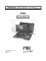
1
EMISSIONS MONITORING SYSTEMS
User manual
OPACITY MONITOR
MRU OPTRANS 1600
Please read before switch on!
F:\TECH-DOC\Optrans1600\User manual
OpTrans1600.DOC
MRU-No. 58375
English
MRU GmbH
1
Introduction........................................................................................................................ 4
1.1
General
4
1.2
Safety Instructions
4
1.3
General
4
1.4
Unpacking and Inspection
5
1.5
Installation
5
1.6
Storage
5
1.7
Repackaging for Shipment
5
1.7.1
1.8
2
6
System Requirements.......................................................................................................... 7
2.1
General Requirements
7
2.2
Spe cification
7
Mechanical........................................................................................................................................................7
Electrical ...........................................................................................................................................................7
Communication................................................................................................................................................8
Environmental..................................................................................................................................................8
Optical ...............................................................................................................................................................8
Pneumatic ..........................................................................................................................................................8
Acoustic noise..................................................................................................................................................8
Opacity ..............................................................................................................................................................8
Functional Description....................................................................................................... 9
3.1
Mechanical Interface
3.1.1
3.1.2
3.1.3
10
Design..............................................................................................................................................................10
Markings.........................................................................................................................................................10
Hose Assembly ..............................................................................................................................................10
3.2
Optical Bench
10
3.3
PNEUMATICS
11
3.3.1
3.3.2
3.3.3
3.4
3.5
Sample tube ....................................................................................................................................................11
Air-Knife-System ..........................................................................................................................................11
Fans..................................................................................................................................................................11
ELECTRONICS
3.4.1
3.4.2
3.4.3
3.4.4
3.4.5
11
Microcontroller PCB inside the optical housing......................................................................................11
Lamp Control .................................................................................................................................................11
Detector Heater Control ...............................................................................................................................12
Adjustment......................................................................................................................................................12
AC Distribution p.c. Board ..........................................................................................................................12
EXTERNALS
3.5.1
3.5.2
3.5.3
3.5.4
4
Interface.............................................................................................................................................................5
Operation and Probe Instruction
2.2.1
2.2.2
2.2.3
2.2.4
2.2.5
2.2.6
2.2.7
2.2.8
3
User Manual for OPTRANS 1600____________________________________ 2 - 2
12
Cleaning Brush...............................................................................................................................................12
Power Cord .....................................................................................................................................................12
Optional Communication Harness..............................................................................................................12
Optional Glass-Attenuators..........................................................................................................................12
Communication Description ............................................................................................ 13
4.1
Serial Communication
13
4.2
Communication Interface
13
5
APPENDIX A OPTRANS 1600 Data Flow Diagram.................................................... 14
6
APPENDIX B: Remote control and display unit............................................................ 15
MRU GmbH
6.1.1
7
User Manual for OPTRANS 1600____________________________________ 3 - 3
Menü:...............................................................................................................................................................17
APPENDIX C: Remote control and display unit............................................................ 19
MRU GmbH
User Manual for OPTRANS 1600____________________________________ 4 - 4
1 Introduction
1.1 General
This manual describes the OPTRANS 1600 (230 V, 24 V and 12V) unit. The OPTRANS 1600 for 230V has an
internal mains power supply. The OPTRANS 1600 for 24V/12V is equipped with an internal switching power
supply and provides +12V, 3 A (peak 5 A) for external use through the communication connector.
All explanations are valid for the above mentioned types. Therefore the product´s name is just OPTRANS 1600.
Specific characteristics of the different OPTRANS 1600 types are pointed out where it is necessary.
1.2 Safety Instructions
NOTE: This apparatus has been designed and tested as a Class 1 device according to DIN 57 411 Pt.1/VDE
0411 Pt.1, Safety Requirements for Electronic Measuring Apparatus, and has been supplied in a safe condition. The present instruction manual contains information and warnings which shall be followed by the user
to ensure safe operation and to retain the apparatus in safe condition.
WARNING! Any interruption of the protective conductor inside or outside the apparatus or disconnection of
the protective earth terminal is likely to make the apparatus dangerous. Intentional interruption is prohibited.
This device must be connected to another apparatus that has an on/off switch. Before switching on the apparatus, make sure that it is set to the voltage of the power supply.
The mains plug shall only be inserted in a socket-outlet provided with a protective earth contact. The protective action shall not be negated by the use of an extension cord without protective conductor.
The opening of covers or removal of parts, except those to which access can be gained by hand, is likely to
expose live parts and high temperature components.
The apparatus shall be disconnected from all voltage sources before any adjustment, replacement or maintenance and repair during which the apparatus shall be opened.
If afterwards any adjustment, maintenance or repair of the opened apparatus under voltage is inevitable, it
shall be carried out only by a skilled person who is aware of the hazard involved.
Make sure that only fuses with the required rated current and of the specified type are used for replacement.
The use of mended fuses and the short -circuiting of fuse holders shall be avoided.
Whenever it is likely that the protection has been impaired, the apparatus shall be made inoperative and be
secured against any unintended operation.
1.3 General
The Opacity Transducer OPTRANS 1600 is designed to measure the smoke emissions of diesel cars and
trucks. The OPTRANS 1600 uses the partial stream technique which provides for direct and continuous
measurement of the smoke sample. This technique measures the amount of light blocked by the sample on a
scale of zero opacity to black with zero obscurity indicating no smoke in the sample cell and black indicating
that the tube is completely blocked. Design criteria conform to French NF R 10-025, the German PTB EO
18-09, ISO 11614 draft and ECE R24, Annex 8/9 specifications.
MRU GmbH
User Manual for OPTRANS 1600____________________________________ 5 - 5
1.4 Unpacking and Inspection
A shipping carton that appears damaged should be inspected and unpacked with the carrier's agent present.
Inspect the instrument for damage (scratches, dents, etc.).
If the instrument is found to be damaged upon receipt, notify the carrier and Sensors Europe immediately.
Retain the shipping carton and the padding material for the carrier's inspection, and for return shipment.
1.5 Installation
The opacity unit is shipped with the probe detached. The probe is secured by a screw clamp located on the
silicone rubber hose. Also included is a 20 mm brush for cleaning.
1.6 Storage
It is strongly recommended that the OPTRANS 1600 be packed as if for re-shipment. Environmental conditions during storage and re-shipment should be as follows:
A) Maximum temperature: 55°C
B) Minimum temperature: -32°C
1.7 Repackaging for Shipment
If possible, use the original shipping container and packing materials. Otherwise:
A) Wrap the OPTRANS 1600 in heavy paper or plastic before placing it
in the shipping container.
B) Use plenty of packing material around the instrument, and
protect the front panel with cardboard or plastic bubble
packing. Protect the instrument with two inch rubberised
foam pads placed along all surfaces of the instrument, or
with a layer of excelsior about 150 mm thick packed firmly
against all surfaces of the instrument.
C) Use a strong, well-sealed shipping container.
D) Mark the container "FRAGILE - DELICATE INSTRUMENT."
1.7.1 Interface
OPTRANS 1600 (230V and 24V/12V):
The OPTRANS 1600 is powered by two separate connectors located on each side of the unit. The 230 VAC
connector is an IEC 320 style that supplies power to the fans, heaters and an isolation transformer. The +/12 VDC power is supplied on the opposite side via a AMP CPC 14-pin connector unless the unit is equipped
with the optional Internal Power Supply (OPTRANS 1600). The AMP CPC 14-pin connector also includes
the RS232 transmit and receive line to communicate to the display.
OPTRANS 1600 (24V/12V):
The OPTRANS 1600 24V/12V has in addition an internal switching power supply that provides another +12
VDC power to an external electrical device. This power is connected to pin 8 of the AMP CPC connector on
the backside of the unit.
MRU GmbH
User Manual for OPTRANS 1600____________________________________ 6 - 6
1.8 Operation and Probe Instruction
The OPTRANS 1600 is operated in three different modes. The first two methods display the real time data
on a screen in order to visually observe exhaust opacity and other internal OPTRANS 1600 measurements.
The third method is used for acceleration testing and records opacity for ten seconds prior to or while uploading the data to a host computer. Refer to Section 5 for software implementation of all three methods.
The following procedure insures that the OPTRANS 1600 is operating properly.
A) Apply AC and DC power.
B) Determine that both fans are operating. Fans are disabled during warmup for
approximately. 3 - 8 minutes.
C) Remove the probe from the tailpipe.
D) Calibrate the OPTRANS 1600
E) Select the real time mode and observe the opacity reading.
The displayed readings should be approximately. 0% . If this result is not observed, repeat the
calibration step.
F) After Calibration was performed properly, connect the probe to the tailpipe.
Therefore the probe should be inserted approximately 30 cm into the tailpipe, unless the design /
arrangement of the tailpipe does not allow this deep. In this case introduce the probe into the
tailpipe as far as possible parallel to the tailpipe wall.
After inserting the probe, fix the position of the probe with the clamp at the wall of the
tailpipe.
Note : Take sample into probe where probe and gas stream in parallel.
Probe
Exhaust Gas Stream
Tailpipe
Probe Clamp
OK
NOT OK
MRU GmbH
User Manual for OPTRANS 1600____________________________________ 7 - 7
2 System Requirements
2.1 General Requirements
•
Opacity type
• Tests
• Reliability
• Ergonomics
•
•
•
•
- Partial flow
- Free Acceleration
- 20,000 hrs.
- Light Weight
- Small Size
Environment
- Garage Environment
Electrical Interface - Compatible with DOT/MDOT
Software Interface - Mostly Compatible with DOT/MDOT
Compliance - ISO 11614 (draft 4/10/92)
- IEC 801-1/-2/-3/-4
- German PTB EO 18-09
- French specification NF R 10-025 (UTAC)
- Dutch specification for Smoke Meters Version 10.1
- Italian specification, Gazetta Uffiziale Nr. 293, del 14/12/96
- UK specification, MOT/07/24/Smoke 2nd rev, Oct.´95
- TÜV Safety/ GS label acc. to EN 61010
- CE Requirements
EN 50 081-1/-2
EN 50 082-1/-2
2.2 Specification
2.2.1 Mechanical
- Size:
- Weight
height = 23.5 cm
width = 38 cm
depth = 9 cm
= 4.5 kg
2.2.2 Electrical
without internal power supply and transformer OPTRANS 1600 230V:
INPUT:
230 VAC + 10 %, - 15 %; 0.67 Amps, 50/60 Hz
+ 12 VDC +/- 5 %; 0.5 Amps
- 12 VDC +/- 5 %; 0.2 Amps
with internal power supply included OPTRANS 1600 24/12V:
INPUT:
230 V version
230 VAC +10 % -15 %; 0.78 Amps, 50/60 Hz
24 V version
24 VAC, 5.8 Amps (peak during warmup), 50/60 Hz
12 V version
12 VAC, 5.8 Amps (peak during warmup)
MRU GmbH
User Manual for OPTRANS 1600____________________________________ 8 - 8
2.2.3 Communication
(To remote control and display unit.)
- RS232 async, 9600 baud, no parity, 1 stop bit
2.2.4 Environmental
Working environment condition:
- Ambient temp. 5º....40º C
- Humidity
0....95 %
- Ambient pollution
2 % max.
Storage condition:
- Storage temp.
-32 ºC....+50 ºC
2.2.5 Optical
- Physical path length
- Optical path length
- inner ∅ of sample cell
- Collimation
- Source light
- Detector
- Response time 1 msec
174 mm
364 mm
20 mm
3°
Green Led 560 nm
Gallium Arsenide
- Stability
- Balanced vacuum
- Probes
Passenger Car Probe
10 mm (ID)
Truck Probe
+/- 1.0 %
- Tube Temperature
75 ºC nominal
2.2.6 Pneumatic
2.2.7 Acoustic noise
- 53 dba
2.2.8 Opacity
- Accuracy
- Resolution
+/- 2 % relative
0.1 %
(standard)
diameters and lengths
(optional)
MRU GmbH
User Manual for OPTRANS 1600____________________________________ 9 - 9
3 Functional Description
MRU GmbH
3.1
User Manual for OPTRANS 1600____________________________________ 10 - 10
Mechanical Interface
3.1.1 Design
The unit is a true Smoke Bench design. It consists of a metal frame carrying all electrical and mechanical components. The frame is designed to be incorporated into a customized housing. The values are available in the
handheld display.
3.1.2 Markings
The serial number tag and logo are located on the bottom of the connector plate. The connector plate is black
anodized. The surrounding screws are zinc plated (clear).
3.1.3 Hose Assembly
The car probe consists of a stainless steel probe and silicone hose material. A handle and clamp assembly is
attached to the probe in order to affix the probe to the tailpipe.
3.2
Optical Bench
The optics is based on a folded light path and consists of a green LED, detector, mirror, convex lens and a beam
splitter. With the source positioned 90° to the optical axis and the beam splitter at 45° the light is reflected by the
beam splitter and collimated by the plano lens. It travels through the sample tube and is reflected at the mirror,
located on the opposite side. From there it travels back through the sample cell and the lens straight to the detector.
Included in the optical housing is the detector heater that maintains the detector at 45° C.
The sample tube is heated to 75° C to avoid condensation, as well as to eliminate autozero errors caused by a
change in intensity due to refraction of light at different temperatures. Also this guarantees a minimum temperature in all location of the sample cell of > 70° C.
MRU GmbH
User Manual for OPTRANS 1600____________________________________ 11 - 11
3.3 PNEUMATICS
3.3.1 Sample tube
The sample tube provides the means of containing the flow of gas in order to be optically measured while heating the sample to prevent thermal phoretic deposition. The length of the tube and the diameter geometrically
determines the collimation of light to be measured. The tube is threaded to further reduce surface reflections.
3.3.2 Air-Knife-System
The Air-Knife-System physically connects the sample tube to the optical housing assembly. Located inside and
immediately above the sample tube outlet is a 2,54 mm diameter pin. This pin causes a venturi effect creating a
slight vacuum for air flow without load. This process allows the sample chamber to purge prior to a calibration.
The air knife also provides a thermal barrier between the sample tube (75° C) and the optical housing (45° C).
3.3.3 Fans
The two fans generate sufficient laminar air flow to overcome the horizontal momentum of the gas particles.
This prevents the optical parts (lens, mirror) from collecting dirt. The air flow also stabilizes the internal case
temperature and cools the optical housing.
3.4 ELECTRONICS
3.4.1 Microcontroller PCB inside the optical housing
The 80C198 is a 16 bit microcontroller operating at 12 MHz. Internal to the controller are the following functions:
- 16 bit timer
- 10 bit A/D converter
- Async serial port
- 8 I/O ports
- Pulse width modulator output
- 28 interrupt sources
- Multiply & divide hardware
The external architecture is designed around an 8 bit data bus and a 16 bit address bus and interfaces to a 32k
RAM and 32k of ROM. A15 is used to decode the two memory devices.
3.4.2 Lamp Control
A constant current source provides 40 mA to a green LED. This circuit contains an enable line that is controlled
by the processor. An additional control line reduces the lamp current to approximately 20 mA . This function
allows the OPTRANS 1600 to perform the auto-attenuation feature (auto 50 % linearity check).
MRU GmbH
User Manual for OPTRANS 1600____________________________________ 12 - 12
3.4.3 Detector Heater Control
A linear current supply (200 mA) controlled by the pulse width modulator output.
3.4.4 Adjustment
Located on the Microprocessor p.c. Board is the detector gain potentiometer, which is factory adjusted to 3.5 4.0 V. The maximum tolerance range for the field is 2800 mV....4600 mV.
3.4.5 AC Distribution p.c. Board
This board contains the electrical interface between the processor and the sample tube heater for 230 VAC & 12
VDC. An optional transformer converts 230 VAC into 12 VDC to power the fans. An optional AC/DC converter
provides the +/- 12 VDC for the electronics and fans when in external 230 VAC only mode.
3.5 EXTERNALS
3.5.1 Cleaning Brush
Stainless steel twisted wire with nylon bristles. Flexible enough to enter the sample tube via the air knife opening
(1.5" radius bend).
3.5.2 Power Cord
External 230 Vac power cord with IEC320 plug and receptacle (20 feet in length).
3.5.3 Optional Communication Harness
The external communication harness consists of an AMP CPC 14 Pin connector (male) that interfaces the OPTRANS 1600 to the remote display unit. The cable is shielded for suppressing high frequency emissions and
braided for durability.
3.5.4 Optional Glass-Attenuators
High precision glass attenuators fitted in a metal frame for certification purpose are available upon request. For
measuring attenuators special commands are to be used!
MRU GmbH
User Manual for OPTRANS 1600____________________________________ 13 - 13
4 Communication Description
4.1 Serial Communication
The serial communication is performed between the OPTRANS 1600 and a remote display unit.
The following command set defines the serial communication.
Baud
Data Bits
Stop Bits
Parity
9600
8
1
none.
4.2 Communication Interface
The serial communication connector on the OPTRANS 1600 is an AMP CPC 14 pin device with
pin assignments described below (separated for each style of OPTRANS 1600). The cable shield
MUST be connected to pin 14 (Chassis Ground) for proper operation . DO NOT connect the
shield to the metal connector housing (alternate construction for the plastic type).
OPTRANS 1600 230V:
Pin 2 Pin 3 Pin 8 Pin 11
Pin 12
Pin 13
Pin 14 -
Rx (into OPTRANS 1600)
Tx (from OPTRANS 1600)
+12 V (1.0 Amps) for fans (required, if no internal transformer)
- 12 V (0.2 Amps)
Digital (Signal) Ground
+ 12 V (0.8 Amps) for electronic p.c. Boards
Chassis Ground (Braided Shield)
OPTRANS 1600 12V:
Pin 2 Pin 3 Pin 8 Pin 12
Pin 14 -
Rx (into OPTRANS 1600 )
Tx (from OPTRANS 1600 )
+12 V for external device
Digital (Signal) Ground
Chassis Ground (Braided Shield)
MRU GmbH
User Manual for OPTRANS 1600____________________________________ 14 - 14
5 APPENDIX A OPTRANS 1600 Data Flow Diagram
Input : Led Intensity
in ADC counts
Ambient temperature
compensation
Output:
Relative Intensity -RI
Raw Data
8B and8C
commands
(not corrected for
optical length )
customized filter
Output
Length
corrected,
filtered,
N[%*10
]
Conversion opacity N[%] to k[m-1 ]
k=−
k
ln
opacity
l
(
ln 1 − opacity
100
)
l
:= intensity
:= natural logarithm
:= opacity
:= 430 mm
The readings in percent from the OPTRANS 1600 to the display are optical path length corrected to
match 430 mm unless it is mentioned differently in this manual (e.g. command 0x8b and 0x8c).
MRU GmbH
User Manual for OPTRANS 1600____________________________________ 15 - 15
6 APPENDIX B: Remote control and display unit
Front view:
ON
OFF
Arrow key
Function key 1
1
Arrow key
2
Function key 2
Switch ON/OFF
RS 232
MRU GmbH
User Manual for OPTRANS 1600____________________________________ 16 - 16
Functions :
1.
Switching the remote display on, following messages appears:
MRU OpTrans
2 remote display
2.
if READY
press F2 key
1.2 ensued in ambient
If the remote display is switch on without connection to the OpTrans
Trancduser not ready...
Please wait... w
3.
1.1 Calibration must be
Transmission error
LCS not found..w
If the Optrans is connected but the instrument is still in warm up mode, following message appears:
low tube temperature
WARM UP
If the warm up is finish, the van of the OpTrans starts
Calibration must be
ensued in ambient air
if READY
press key F2
Now the measuring mode can start with F2:
Calibration
Zeropoint =
After few seconds the instrument switches in the main menu
If you use the st-keys, you can change among three modes.:
2.1 Measurement:
START F1
Mode change
F1
Cont. Measurement F2
Data transmit
Service
F1
F2
MRU GmbH
User Manual for OPTRANS 1600____________________________________ 17 - 17
6.1.1 Menu
Mode change
F1
Cont. Measurement F2
2.3 Measurement:
START F1
F1
F1
F2
Modus:B Change – F1
2.7 STOP F1
42,5% 40,8% 39,2%
After three measurements following
Message appears
2.6 Cancel- s t ;
F2
OK.-
If you use F1, you change the mode.
Done... Press any
key to continue
Calibration must be
ensued in ambient air
2.8 Measurement:
START F1
if READY
press key F2
Mainmenu
Results
F1
st
Calibration
Zeropoint =
s
t
F1
Opacity(%)
Opacity k
42,5%
10,005
2.10 MAX 1:Opacity
42,5%
Opacity k
12.404
If you use thet key, you switch among the
three values in the display.
To Stop the continues measurement
you can use any key. .
MRU GmbH
User Manual for OPTRANS 1600____________________________________ 18 - 18
Menu:
Data transmit
Service
F1
F2
F1 starts the transfer of the last
three values to the DELTA
1600 L
F1
F2 – only for Service
Data transmit:
Chancel...
F2
MRU GmbH
User Manual for OPTRANS 1600____________________________________ 19 - 19
7 APPENDIX C: Remote control and display unit