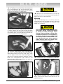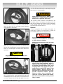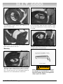
1
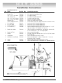
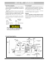
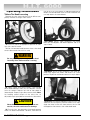
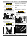
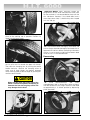
®
H.I.T. 6000
TRUCK TIRE CHANGER
Installation
Operating
Safety
Maintenance
Instructions
Instructions
Instructions
Instructions
READ these instructions before placing unit in
service KEEP these and other materials delivered
with the unit in a binder near the machine for
ease of reference by supervisors and operators.
1601 J. P. Hennessy Drive, LaVergne, TN USA 37086-3565 615/641-7533 800/688-6359
HENNESSY INDUSTRIES INC. Manufacturer of AMMCO®, COATS® and BADA® Automotive Service Equipment and Tools.
Manual Part No.: 9120583 02
Revision:
01/02
Safety
ii • COATS H.I.T. 6000 Changer
Contents
Table of Contents
Operator Protective Equipment . . . . . . . . . . . . . . . . . . . . . . . . . . . . . . . . . . . . . . . . . . . .iv
Definitions of Hazard Levels . . . . . . . . . . . . . . . . . . . . . . . . . . . . . . . . . . . . . . . . . . . . . . .iv
Safety Instructions
Bead Loosening . . . . . . . . . . . . . . . . . . . . . . . . . . . . . . . . . . . . . . . . . . . . . . . . . . . . . .v
Demounting & Mounting . . . . . . . . . . . . . . . . . . . . . . . . . . . . . . . . . . . . . . . . . . . . . . .v
Inflation . . . . . . . . . . . . . . . . . . . . . . . . . . . . . . . . . . . . . . . . . . . . . . . . . . . . . . . . . . . . .v
Installation Instructions . . . . . . . . . . . . . . . . . . . . . . . . . . . . . . . . . . . . . . . . . . . . . . . . . .vi
Electrical Installation . . . . . . . . . . . . . . . . . . . . . . . . . . . . . . . . . . . . . . . . . . . . . . . . . .1
Air Installation . . . . . . . . . . . . . . . . . . . . . . . . . . . . . . . . . . . . . . . . . . . . . . . . . . . . . . .1
General . . . . . . . . . . . . . . . . . . . . . . . . . . . . . . . . . . . . . . . . . . . . . . . . . . . . . . . . . . . . .1
Principal Operating Parts . . . . . . . . . . . . . . . . . . . . . . . . . . . . . . . . . . . . . . . . . . . . . . .1
Operating Instructions . . . . . . . . . . . . . . . . . . . . . . . . . . . . . . . . . . . . . . . . . . . . . . . . . . .2
Tubless Tire Bead Loosening . . . . . . . . . . . . . . . . . . . . . . . . . . . . . . . . . . . . . . . . . .2 - 3
Multiple Piece Rim Bead Loosening . . . . . . . . . . . . . . . . . . . . . . . . . . . . . . . . . . . . . .3
Clamping . . . . . . . . . . . . . . . . . . . . . . . . . . . . . . . . . . . . . . . . . . . . . . . . . . . . . . . . .3 - 4
Demounting . . . . . . . . . . . . . . . . . . . . . . . . . . . . . . . . . . . . . . . . . . . . . . . . . . . . . . .4 - 5
Mounting . . . . . . . . . . . . . . . . . . . . . . . . . . . . . . . . . . . . . . . . . . . . . . . . . . . . . . . . .5 - 6
Inflation . . . . . . . . . . . . . . . . . . . . . . . . . . . . . . . . . . . . . . . . . . . . . . . . . . . . . . . . . . . . .6
Special Instructions for “Duplex” or “Super Single” Tires . . . . . . . . . . . . . . . . . . .7 - 8
Mounting . . . . . . . . . . . . . . . . . . . . . . . . . . . . . . . . . . . . . . . . . . . . . . . . . . . . . . . . . . .8
Maintenance . . . . . . . . . . . . . . . . . . . . . . . . . . . . . . . . . . . . . . . . . . . . . . . . . . . . . . . . . . .9
Truck Tire Changer Warranty Policy . . . . . . . . . . . . . . . . . . . . . . . . . . . . . . . . . . . . . . .Back
Service Policy . . . . . . . . . . . . . . . . . . . . . . . . . . . . . . . . . . . . . . . . . . . . . . . . . . . . . . . .Back
COATS H.I.T. 6000 Changer • iii
Safety
WARNING
Read entire manual
before assembling,
installing, operating,
or servicing this
equipment.
WARNING
Failure to follow danger, warning, and caution
instructions may lead to serious personal injury or
death to operator or bystander or damage to property. Do not operate this machine until you read
and understand all the dangers, warnings and cautions in this manual. For additional copies of either,
or further information, contact:
Hennessy Industries, Inc.
1601 J.P. Hennessy Drive
LaVergne, TN 37086-3565
(615) 641-7533 or (800) 688-6359
www.ammcoats.com
Operator Protective
Equipment
Personal protective equipment helps make tire servicing safer. However, equipment does not take the
place of safe operating practices. Always wear durable
work clothing during tire service activity. Loose fitting
clothing should be avoided. Tight fitting leather gloves
are recommended to protect operator’s hands when
handling worn tires and wheels. Sturdy leather work
shoes with steel toes and oil resistant soles should be
used by tire service personnel to help prevent injury in
typical shop activities. Eye protection is essential during tire service activity. Safety glasses with side
shields, goggles, or face shields are acceptable. Back
belts provide support during lifting activities and are
also helpful in providing operator protection.
Consideration should also be given to the use of hearing protection if tire service activity is performed in an
enclosed area, or if noise levels are high.
iv • COATS H.I.T. 6000 Changer
Definitions of Hazard
Levels
Identify the hazard levels used in this manual with
the following definitions and signal words:
DANGER
Watch for this symbol:
DANGER
It Means: Immediate hazards, which will result in
severe personal injury or death.
WARNING
Watch for this symbol:
WARNING
It Means: Hazards or unsafe practices, which could
result in severe personal injury or death.
CAUTION
Watch for this symbol:
CAUTION
It Means: Hazards or unsafe practices, which may
result in minor personal injury or product or property
damage.
Watch for this symbol! It means BE ALERT! Your
safety, or the safety of others, is involved!
Safety
Safety Instructions
WARNING
Only properly trained personnel should
service tires on the H.I.T. 6000. Read all
safety and operating instructions thoroughly before using the tire changer.
ALWAYS remove all wheel weights and the valve
core to deflate the tire before servicing.
ALWAYS cover the electric motor and switch box
before hosing down the tire changer. Be sure water
does not enter the motor or switch box.
ALWAYS disconnect the electric power and air supply before attempting any maintenance.
ALWAYS keep all working surfaces clean and free of
tire lube buildup.
ALWAYS be aware of what each person is and will do
before attempting any two-person operation.
Bead Loosening
NEVER place anything between the bead loosener
disc and the tire/wheel.
NEVER place any part of your body between the
bead loosener disc and the tire/wheel, severe bodily
injury may result.
NEVER allow the bead loosener to contact the
wheel, wheel damage may occur.
Demounting & Mounting
NEVER stand on the working table while demounting or mounting a tire.
ALWAYS keep hands, feet, and other objects away
from moving parts while the machine in turned on.
ALWAYS place the narrow bead seat to the outside
when clamping. Failure to demount the tire from the
narrow bead seat side may cause damage to the tire
beads.
ALWAYS apply an approved rubber lubricant to rim
flanges and both tire beads before demounting or
mounting and seating the beads. NEVER use
antifreeze, silicone, or petroleum base lubricants.
ALWAYS clean and inspect the wheel.
NEVER mount a tire on a damaged or rusty wheel.
Wheel damage or rust may cause tire or wheel failure
during inflation. Explosion from failure may result in
severe injury or death of the operator and bystanders.
ALWAYS be sure the bead opposite the tool is in the
drop center before rotating the tire when demounting
or mounting to avoid damage to the tire beads.
Inflation
ALWAYS follow all applicable Local, State, and
Federal Codes, Rules, and Regulations; such as the
Federal OSHA Standard Number 1910.177.
NEVER seat beads or inflate a tire on the tire
changer. The H.I.T. 6000 is not designed as a safety
device or stand for bead seating or inflation.
ALWAYS use an approved inflation chamber or inflation cage.
The following safety instructions are for one piece
wheels only. Refer to the manufacturer’s or R.M.A.
procedures for multipiece wheels.
ALWAYS use an approved inflation chamber or inflation cage equipped with a grip chuck and a remote
inflation gauge and valve. DO NOT OVER INFLATE!
Tire or wheel failure during and after inflation may
result in an explosion capable of causing severe injury
or death.
ALWAYS inflate the tire to manufacturer’s recommended cold operating pressure.
NEVER reinflate a tire that has been run underinflated or flat without first demounting the tire and
checking for wheel and tire damage.
ALWAYS inspect the tire interior for loose or broken
cords, cuts, penetrating objects, and other damage to
the carcass. Discard tires that cannot be properly
repaired.
NEVER rework, weld, heat or braze wheels.
NEVER strike the tire or wheel with a hammer.
ALWAYS be sure the tire diameter exactly matches
the wheel diameter.
DANGER
Tire failure under pressure can be hazardous. Place the wheel inside an approved
inflation chamber or cage before inflating.
Use an approved remote inflation valve,
hose, and gauge. ALWAYS wear safety goggles for eye protection. Do not stand beside
the wheel or cage during inflation. Keep
hands and other parts of the body out of
the cage during inflation. Observe the tire
pressure frequently. Do not exceed the
manufacturer’s recommended maximum
inflation pressure. Failure to follow these
instructions may cause the tire and rim to
separate with tremendous force, resulting
in serious personal injury or death.
COATS H.I.T. 6000 Changer • v
H.I.T. 6000
Installation Instructions
Parts Box Check List
Ref. Name
Part No.
Qty.
1
2
3
4
Fastener Package
Detent Pins
1/4” x 1-1/2” Cap Scew
1/4” Locknut NC
3/8” x 3/4” Self-Tap Bolt
1/4” x 1-1/4” Cap Screw
Breather Cap
Quick Coupler-Female Fit.
B.L. Shoe W/C
B.L. Rim Stop
Pivotal Shoe Assy.
B.L. Pedal Assy.
7120393
7120326
7105390
7000591
7106300
7120321
7120291
7120440
7120112
7120513
7120545
7120396
1
5
1
2
4
1
1
1
1
1
1
1
5
Bead Lifter Holder
7120328
1
6
7
Bead Lifter Tool
Handle
7120332
7120391
1
1
8
9
Lube Bottle
Hold Down-Lube Bottle
7120347
7120346
1
1
10
11
Spring
Swab
7101106
7120366
2
1
0
vi • COATS H.I.T. 6000 Changer
Assembly Instructions
Contains the following nuts, bolts, pins, and screws.
B.L. shoes and stop connections
B.L. pedal asembly
B.L. pedal & handle connection
Fastener bead lifter holder
Secures PN 8120391 handle
Switch with solid cap in reservoir
To be used on owners air supply connection to machine air inlet
Install with (2) PN 7120326 detent pins
Install with (1) PN 7120326 detent pins
Install with (2) PN 7120326 detent pins
Attach to pedal extention with (1) PN 7105390 1/4” x 1-1/2”
cap screw and (1) PN 7000591 1/4” lock nut
Can be installed in two positions, see diagram. Secure with
(4) PN 7106300 3/8” x 3/4” self tapping bolts
Insert in bead lifter holder
Fits over valve shaft. Secure with (1) 1/4” x 1-1/4” NC screw
& 1/4” lock nut
Place in bracket on top of B.L. cover
Place over lube bottle “v” down. Bottom of “v” must be
located over holes in bracket.
Hook to hold down and bracket on B.L. cover
Place in lube bottle (Note: Fill lube bottle with approved lubricant)
H.I.T. 6000
Electrical Installation
Air Installation
The H.I.T. 6000 requires 220 volt, 3 phase or optional
single phase power source. Caution: Only a licensed
electrician should install power source and hook up
the H.I.T. 6000.
A quick coupler is provided for disconnecting the air
supply during maintenance procedures. The male fitting is on the inlet hose. The female is in the parts bag
for installation on the owner’s air supply hose.
Important: Installation of this unit in an area where
gasoline, gasoline fumes, or other flammable vapors
are present requires a motor/switch riser kit (PN
7120433) to meet national electrical codes; including
paragraphs 500-4, 501 (1-8), 511 (1-5), PP 70-377.
For lubrication of internal air system, a lubricator
should be installed in the air supply line.
Disconnect power source and check with volt-ohm
meter to assure power is off before connecting wires
of machine.
General
The H.I.T. 6000 does not require bolting to the floor.
However, if desired, the two holes located at the back
of the machine, used for mounting on the pallet,
should be used. DO NOT BOLT AT THE FRONT OF
THE MACHINE.
CAUTION
Motor rotation must be clockwise looking
at top of motor. If counterclockwise,
reverse any two of the power wires.
Principal Operating Parts
COATS H.I.T. 6000 Changer • 1
H.I.T. 6000
Operating Instructions
Tubless Tire Bead Loosening
Remove the valve core and allow tire to deflate completely. Remove all weights from wheel.
1. Install rim stop in the appropriate position for tubeless tires. See illustration.
tires on rusty rims may require an additional operation to
loosen the second bead. Here are three methods that
can help loosen the second bead.
Spin Wheel: Retract shoes completely. Roll wheel
back, spin 180 degrees and loosen opposite side as in
step 2 above.
Position tire between bead loosener shoes: short drop
center side toward shoe with rim stop.
WARNING
Do not place any part of body between bead
loosening shoes while machine is running.
Roll Wheel: Retract shoes completely. Roll wheel forward firmly against the rollers and rotate it to a new
position. Reposition and loosen bead as in step 2 above.
2. Adjust shoes and loosen beads: using handle,
adjust bead loosener shoes on tire sidewalls 1/4-inch
from rim contour. Depress left side of foot pedal to
loosen beads. Depress right side to retract shoes. Note:
for handling several wheels of the same size, an
adjustable stop is provided for convenience. (See arrow.)
CAUTION
Never allow both bead loosening shoes to contact rim, since this could cause rim damage.
3. For most tires, one operation of the bead loosener
shoes will loosen both beads. However, some difficult
2 • COATS H.I.T. 6000 Changer
Angle Tire: (not recommended for aluminum rims) The
shoe with the rim stop may itself be used as a rim stop.
Angle the wheel so that this shoe contacts the rim and
the opposite shoe contacts the unloosened bead.
H.I.T. 6000
CAUTION
Allowing both shoes or one shoe and the
rim stop to contact the rim during bead
loosening may cause rim damage.
Multiple Piece Rim Bead Loosening
WARNING
BEFORE ATTEMPTlNG TO LOOSEN BEADS,
REMOVE THE VALVE CORE AND BE SURE
THE TlRE IS COMPLETELY DEFLATED. DO
NOT PLACE ANY PART OF THE BODY
BETWEEN BEADLOOSENER SHOES.
ring, pull handle to bring the kicker shoe up to the
bead. Continue to full stroke of bead loosener.
4. Disengage bead loosener shoes and turn tire 90
degrees and repeat steps 1,2, & 3 until bead is loosened.
5. Use bead loosen shoes to hold tire and remove
lock ring.
6. To loosen other bead, remove wheel assembly
from between the shoes and pivot tire 180 degrees to
position the ring side of the wheel near rim stop.
Repeat steps 2, 3, 4 above.
WARNING
ALWAYS lNFLATE TlRES lNSlDE A SAFETY
INFLATlON CAGE. TlRE EXPLOSlON
DURlNG lNFLATlON CAN CAUSE SERlOUS
lNJURY OR DEATH.
Clamping
1. Place rim stop in tube type tire position; see illustration.
2. Position tire between bead loosener shoes with
the ring(s) toward the kicker shoe.
Position bead loosener shoe with 1/4” of lock ring.
CAUTION
DO NOT LET SHOES PUSH ON RIM OR
LOCK RING(S). RIM OR RlNGS MAY
BECOME WARPED AND DAMAGED.
3. Actuate bead loosener so that the bead loosener
shoe pushes bead in. As the kicker shoe passes the
1. Raise working table: Raise working table to
almost vertical position by pulling back on the control
handle. Open clamps by twisting the control handle
counter-clockwise.
2. Clamp Adjustment: Adjust all three clamps to the
proper wheel diameter range. The front hole position is
for 19.5” to 24.5”. The rear hole position is for 16” to
19.5”.
COATS H.I.T. 6000 Changer • 3
H.I.T. 6000
Aluminum Wheels: Many aluminum wheels are
designed for the tire to be mounted from either side.
For these wheels it is recommended to clamp with the
disc side down. However, if the wheel does have a
short drop center side, it should always be clamped
with this side up.
3. Position Wheel: Roll wheel onto the safety skirt as
close to the working top as possible. Position rim
flange into the lower clamp.
5. Lubricate both beads thoroughly: Both beads and
the rim flange should be thoroughly lubricated with an
approved tire lubricant before attempting to demount
the tire. It may be easier to lubricate the bottom bead
while the tire is in the bead loosener.
Demounting
4. Clamp Rim: With the left hand on the top front of
the rim, push the rim toward the upper two clamps.
Then close the clamping jaws by twisting the control
handle clockwise. Observe the clamping action to
make sure all three clamps are properly engaged.
Lower working table to desired angle by pushing forward on control handle.
CAUTION
Make sure the short drop center side of the
wheel is toward the operator. Attempting to
demount tire from the long drop center side
may damage the tire bead.
4 • COATS H.I.T. 6000 Changer
1.
Install
Mount/demount
Tool:
Insert
mount/demount tool in square drive socket and position tool head on the rim flange. Rotate the tool head
to approximately a 12 o’clock position by depressing
either foot pedal.
H.I.T. 6000
2. Lift Top Bead: insert bead lifter under top bead to
left of mount/demount tool and lift bead over lower
blade of the tool head. Note: Make sure the top bead
at the 6 o’clock position is in drop center.
CAUTION
Always demount by rotating tool clockwise.
5. Remove Tire: The demounted tire can now be
removed. On heavier tires raising the working table will
help lift the tire to a vertical position.
Mounting
1. Before Mounting tire on a used rim, be sure
flange area (particularly the bead seat area) is clean and
smooth. Remove any buildup of rust, corrosion or old
rubber with wire brush.
CAUTION
3. Demount Top Bead: Holding the bead lifter down
as shown, depress the front side of either foot pedal
thus rotating the tool head clockwise and demounting
the top bead. Make sure mount/demount tool does not
rotate into bead lifter during the operation.
4. Demount Bottom Bead: Return mount/demount
tool to the 12 o’clock position and insert bead lifter
under bottom bead to the left of head. Again, make
sure the opposite side of the bottom bead goes into
drop center. Lift bottom bead over tool blade. Hold the
bead lifter mount/demount tool clockwise and
demounting bead. Make sure tool does not rotate into
bead lifter during the operation.
Never mount a tire on a rim where any parts
show cracks, damage, or have been repaired
by welding or brazing. Thoroughly inspect
inside of casing for damage or foreign material. Make sure that the tire is completely dry,
as moisture deteriorates the cord fabric of the
tire and may result in eventual failure of the
tire. Lubricate both beads with an approved
rubber lubricant. Never use silicones, antifreeze, or petroleum base solutions.
2. Lubricate Rim: After inspecting rim, thoroughly
lubricate both bead seats with approved tire lubricant.
3. Lubricate Tire Beads: After inspecting tire thoroughly, lubricate both beads inside and out with an
approved lubricant.
COATS H.I.T. 6000 Changer • 5
H.I.T. 6000
ing tool clockwise and mounting the top bead. Make
sure that the bead following the tool keeps sliding into
drop center as the tool rotates.
WARNING
Never inflate tire on the H.I.T. 6000. It is not
intended as a safety device for inflation.
Always use an approved safety cage.
4. Position Tire: Lower table to a comfortable angle
and rotate tool to approximately the 7 o’clock position.
Lean tire over the rim and hook lower bead on
mount/demount tool handle.
7. Remove Wheel: Remove mount/demount tool
from drive socket. If tool appears jammed, reverse the
tool slightly by depressing the back of either foot pedal.
Raise working table and release clamps by twisting
control handle counter-clockwise.
Inflation
These instructions are for tubless one piece rim
wheels only. Follow tire manufacturer’s or RMA recommended procedures for multi piece rims.
DANGER
Do not attempt to inflate tire on the tire
changer. It is not intended as a restraining
or safety device for inflation.
Always use approved safety cage and safety
procedures.
5. Mount Bottom Bead: Depress front of either foot
pedal, thus rotating the tool clockwise. Hold down on
the tire until the tool begins to mount the bottom bead.
Make sure the bead goes into drop center behind the
tool head.
CAUTION
Keep hands away from the tire beads and
tool head during operation.
6. Mount Top Bead: With tool head at approximately
the 7 o’clock position, push top bead over tool head
and hold bead into rim drop center with the bead lifter
as shown. Depress front of right foot pedal, thus rotat-
6 • COATS H.I.T. 6000 Changer
Tire failure under pressure can be hazardous, place wheel completely inside an
approved safety cage before inflating. Use
an approved remote inflation valve, hose
and gauge. Wear safety goggles for eye protection. Do not stand beside wheel or cage
during inflation. Observe pressure frequently and do not exceed the tire’s recommended maximum inflation pressure.
Failure to follow these instructions can
cause tire or rim to separate with tremendous force and can lead to serious personal
injury or death.
H.I.T. 6000
Special Instructions for “Duplex” or
“Super Single”Tires
Wheel Preparation: Remove valve core and allow tire
to deflate completely. Remove all wheel weights.
1. Adjust Bead Loosener Shoes: For tire width of 10”
and over, one or both bead looseing shoes should be
adjusted.
2. Position Tire and loosen beads as explained in the
bead loosening section.
3. Clamping: Due to the stiff sidewall, it may be necessary to push down on the rim at the top as the
clamps are being closed , to engage the rim. Lowering
the table slightly will let the wheel’s weight help in
clamping.
4. Lubricate tire beads and rim flange thoroughly: It
may be easier to lubricate the top bead by letting the
mount/demount tool push down on the bead and then
rotating the tool with the lube swab following the tool.
Demount the top bead in the usual manner). See section one.
5. Position Tire: It will be necessary to get the bottom bead into drop center by raising the working table
to almost vertical (do not allow the tire to touch floor).
Pull out on tire as shown until bottom bead moves into
drop center. Then raise working table until tire rests on
floor to hold it in drop center.
6. Insert Bead Lifter: With bottom bead in drop center and tire resting on the floor, rotate tool to 9 o’clock
position and insert bead lifter under bottom bead just
below the tool head.
COATS H.I.T. 6000 Changer • 7
H.I.T. 6000
7. Demount Bottom Bead: Lift bead over
mount/demount head. Rotate tool clockwise to
demount bottom bead.
8. Remove Tire: After demounting the bottom bead,
lower table to free rim from tire.
Mounting
1. Mount Bottom Bead: With the table at a comfortable angle, mount the bottom bead in the ususal manner. It may be necessary to lift the bottom bead into
drop center as the mount/demount tool rotates.
8 • COATS H.I.T. 6000 Changer
2. Position Top Bead: Manipulate and position the tire
so that the bottom bead slips down toward its bead
seat and the top bead rests evenly around the upper
rim flange.
3. Mount Top Bead: Use bead lifter to hold top bead
into drop center while tool rotates.
WARNING
Never inflate tire or seat beads while on the
tire changer. It is not intended as a safety
device for inflation. Always use an approved
safety cage for tire inflation.
H.I.T. 6000
Maintenance
WARNING
Before attempting any maintenance, disconnect electrical power and air supply.
CAUTION
machine. Remove cover plate and disconnect quick
coupler connection between air valve and cylinder. Use
fair amount of spray lubricant.
Loss of power and/or excessive pump noise
indicates low oil. Shut off machine immediately or damage to pump and motor will
result. Damage resulting from insufficient oil
is not covered under warranty.
6. Lubricate Ring Gear: To gain access to the pinion
and ring gear, remove the COATS name plate located
on the working table. With a small brush or grease gun,
apply AGMA #1 or #2 grease liberally on the ring gear
teeth.
1. Oil Level Check: Remove filler cap and check oil
level on dip stick. Fill to proper level as needed. Use
hydraulic oil only.
3. Oil Air Lines: Disconnect air supply at rear of
7. Oil Filter Change: Disconnect electircal power.
Remove cover panel and place a shallow pan under oil
filter. Remove oil filter with standard auto oil filter grip
or wrench. Replace with service part #120222.
COATS H.I.T. 6000 Changer • 9
Truck Tire Changer Warranty Policy
The COATS Company warrants the H.I.T. 6000 Truck Tire Changer to be free of defects in workmanship and
material for a period of twelve (12) months from the date of installation. Labor will be covered by the COATS®
Company for a period of 90 days from the date of installation.
®
Upon inspection by COATS® Company or its authorized representative, any defect in workmanship and/or material within the warranty period will be:
Replaced in the field by the user, parts supplied free of charge by the COATS® Company, LaVergne, Tennessee,
for the first 12 months of operation. Labor is covered by the COATS® Company for the first 90 days of operation.
This warranty is in lieu of all other warranties, expressed or implied, and of all other obligations and/or liabilities,
and no person is authorized to make any other representation or assume any other obligation on behalf of the
manufacturer.
This warranty shall not apply if damage is due to accident, negligence, alteration, abuse or misuse, worn parts,
installation by unlicensed electrician, or has not been operated in accordance with the manufacturer's instructions
for operation. Parts replaced under warranty will assume the remainder of the unit's warranty period. Only parts
and accessories manufactured by the COATS® Company will be warranted as stated above and this warranty shall
not apply to the tire changer or any parts thereof if parts and accessories not manufactured by COATS® Company
are used as replacements for or in substitution of COATS® Company manufactured parts and accessories.
To validate warranty:
1. A licensed electrician must install all electrical requirements and sign the attached warranty registration card.
2. The owner must fill out the post-paid warranty registration card and return it to COATS® Company within thirty
(30) days of installation.
Failure to perform 1 above will void warranty coverage on electrical and hydraulic components. Failure to perform
2 may void entire warranty.
Service Policy
Upon recognition of a problem, review the Maintenance Instructions and Service Manual.
If further assistance is required, call:
(800) 688-6359
or
your nearest
Hennessy Regional
Office
The COATS® Company will supply a replacement part-no charge- when it is determined by the factory or an
authorized representative that the part is defective in workmanship and/or material and is covered by the warranty
policy. The owner has the option to send the defective part to the COATS® Company for inspection, repair or
replacement. All returns to the factory must be authorized by the COATS® Company prior to return. Freight to the
factory will be paid by the owner. If the machine is serviced by COATS® authorized personnel, labor charges will
be covered for a period of 90 days after the date of installation.
9120583 02 01/02
© Copyright 1994 Hennessy Industries and COATS®
All Rights Reserved
Printed in USA