1
AC
Electro-Motor
Cruise System
Service Manual
IM PO RTAN T S A F E T Y NOTICE
To reduce the chance of personal injury and/or property damage, the following
instructions must be carefully observed:
Proper service and repair are important to the safety of the service technician and the
safe, reliable operation of all motor vehicles. If part replacement is necessary, the part
must be replaced w ith one of the same part number or with an equivalent part. Do not
use a replacement part of lesser quality.
The service procedures recommended and described in this service manual are
effective methods of performing service and repair. Some of these procedures require
the use of tools specially designed for the purpose.
Accordingly, anyone who intends to use a replacement part, service procedure or tool,
which is not recommended by the vehicle manufacturer, must first determine that
neither his safety or safe operation of the vehicle will be jeopardized by the
replacement part, service procedure or tool selected.
It is important to note that this manual contains various "cautions” and "notices” that
must be carefully observed in order to reduce the risk of personal injury during service
or repair, or the possibility that improper service or repair may damage the vehicle or
render it unsafe. It is also important to understand that these "cautions” and "notices"
are not exhaustive, because it is impossible to warn of all the possible hazardous
consequences that might result from failure to follow these instructions.
130
Central Office
CHEVROLET
EEJ
May 27,
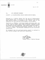
TO:
ALL CHEVROLET DEALERS
SUBJECT:
AC ELECTRO-MOTOR CRUISE SYSTEM SERVICE MANUAL
1987
Enclosed is a Service Manual for the new AC Electro-Motor
Cruise System that is utilized on 1988 Chevrolet C-K Trucks.
This service manual is intended to be a quick, easy to use
reference for servicing the Electro-Motor Cruise System.
Chevrolet is offering a training program concerning this new
cruise control system, plus other electrical components used
on the 1988 C-K Truck through General Motors Training Centers
and remote training locations. The course number is 10488.01,
"1988 C-K Truck Electrical/Electronics Program", and is one
(1) day in length. We encourage attendance by your electrical
technicians.
We recommend that the enclosed,service manual be reviewed by
your service manager and electrical technicians.
General Sales & Service Manager
Chevrolet Motor Division
General Motors Corporation
30007 Van Dyke Avenue. Warren. Michigan 48090
Foreword
AC Electro-Motor Cruise System Service Manual
/ \ V ~ / Spark Plug Division of General Motors Corporation has prepared this service manual to
help answer questions about the operation and service of the AC Electro-Motor Cruise System
(EMCS).
The AC Electro-Motor Cruise System is an extension of the electronic cruise control systems
that AC Spark Plug Division has designed and manufactured since the 1977 vehicle model year.
The EMCS has been engineered to function as an all-electric system.
Like Custom Cruise III, the Electro-Motor Cruise System places at the driver's fingertips the
cruise control functions of CRUISE, COAST, RESUME, TAP-UP, TAP-DOWN, and ACCELERATE.
Each function is controlled by either the slider switch or the push button on the turn signal lever.
The EMCS makes use of an electric motor and connecting strap to vary the throttle angle. As a
result the motor-actuated throttle linkage affords a mode of operation that is completely
vacuum independent and consistently gives smoother throttle control under changing driving
conditions.
Electro-Motor Cruise System also offers serviceability benefits:
(A) EMCS has less than half the system parts of the Custom Cruise III
system
(B) Major cruise components are reduced from four (4) to tw o (2)
(C) No vacuum harnesses w ith difficult-to-Iocate leaks are needed
{D! Built-in diagnostics provide a check of the cruise system operation
This service manual is intended to be a quick, easy-to-use reference for servicing the ElectroMotor Cruise System. It has been organized into seven major sections...
1.
2.
3.
4.
5.
6.
7.
General Description of Electro-Motor Cruise System
How to Use the Electro-Motor Cruise System
Components in the Electro-Motor Cruise System (GMT-400)
Electro-Motor Cruise System Block Diagram and System Layout (GMT-400)
GMT-400 Cruise Diagnosis and Troubleshooting
Connector Disassembly and Repair
Cruise Control Cable Installation and Adjustment Procedures
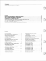
Contents
AC Electro-Motor Cruise System Service Manual
Foreword..............................................................................................................................................................1
General Description of Electro-Motor Cruise System .................................................................................... 3
How to Use the Electro-Motor Cruise System ................................................................................................ 4
Components in the System (G M T-400)..........................................................................................................6
Electro-Motor Cruise Block Diagram and System Layout (GMT-400)......................................................... 8
GMT-400 Cruise Diagnosis and Troubleshooting .......................................................................................12
Connector Disassembly and Repair...............................................................................................................20
Cruise Control Cable Installation and Adjustment P ro ced u res................................................................ 24
Illustrations
Cruise Control M o d u le ..............................................
Mode Control Switches on Turn Signal Lever . . . .
Internal Transmission Speed S ensor.......................
Combination Cruise/Stop Light/
Converter Clutch S w itc h .......................................
Plunger Type Cruise Release S w itch .....................
Cruise Control M o d u le ..............................................
Block Diagram, Electro-Motor Cruise System . .
Installation on LB4 (4.3L), L03 (5.0L),
L 0 5 I5 .7 L ) ..............................................................
Installation on LH6 & LL4 (6.2L D iesel)..................
Installation on L19 (7.4L) .........................................
Cruise Mode S w itch Location; Steering C o lu m n . .
Clutch Release S w itch Location;
Behind Instrument P a n e l.......................................
Brake Release/Redundant Release
S w itch Location: Behind Instrument Panel . . . .
Cruise Module Location; Engine
Compartment B u lk h e a d .......................................
Wiring Harness Location: Behind
Instrument Panel on L e ft.......................................
Convenience Center Location;
Behind Instrument P a n e l.......................................
. . . 3
. . . 4
. . . 6
.
.
.
.
.
.
.
.
..
. .
. .
. .
.
.
.
.
6
7
7
8
. 9
. 9
. 9
10
. 10
. . 10
. . 10
.1 1
. . 11
2-Wheel Drive Speed Sensor Location:
Transmission...........................................................
Chart: Road Test o f Cruise System .......................
Voltmeter H o o ku p ......................................................
Cruise Mode Switch Connector ( C 3 A !..................
GMT-400 Cruise Diagnostic C h a rt..........................
Electro-Motor Cruise System Circuit Schematic . .
Schematic Symbol E xplanation...............................
Cruise Module Connector R e m o v a l.......................
Connector (C4A) Retainer R e m o v a l.......................
Connector {C4A! Terminal R e m o va l.......................
Re-forming Locking T a n g .........................................
Connector (C4A) T e rm in a l.......................................
Cable Installation (Step 1 }.........................................
Cable Installation (Step 2) .......................................
Cable Installation (Step 3 ) .......................................
Cable Installation (Step 4) .......................................
Cable Installation (Step 5 A ) ....................................
Cable Installation (Step 5BI ....................................
Cable Installation (Step 6) .......................................
Cable A djustm ent (Diesel L e v e r)............................
Cable A djustm ent (Step 4 ) .......................................
Cable Adjustm ent (Step 5 ) .......................................
..11
. . 14
. . 15
. . 15
. . 16
. . 18
. . 19
?0
?1
. . 21
. . 22
. . 22
. . 24
. . 24
. . 24
. . 25
. . 25
. . 25
. . 25
. . 26
27
. . 27
General Description of Electro-Motor Cruise System
AC Electro-Motor Cruise System Service Manual
The Electro-Motor Cruise Control is a speed control
system which maintains a desired vehicle speed under
normal driving conditions. The Electro-Motor Cruise
Control System has the capability to CRUISE, COAST,
RESUME SPEED, ACCELERATE,TAP-UP, and TAP-DOWN.
The main parts of the cruise control system are the
mode control switches, cruise control module, electri
cal release switches, electrical harness, and cruise
control cable.
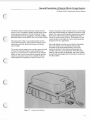
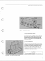
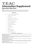
The cruise control system uses a cruise control module
to obtain the desired vehicle cruise operation {see
Figure 1-1). Two important components in the module
help to do this. One is an electronic controller and the
second is an electric motor. The controller monitors
vehicle speed and operates the electric motor. The
Figure 1-1
motor in response to the controller moves a connecting
strap and throttle linkage to maintain the desired cruise
speed. The cruise control module contains a low speed
limit which wilt prevent system engagement below a
minimum speed, about 25 MPH. The operation of the
cruise module is controlled by mode control switches
located on the turn signal lever.
Electrical release switches are provided to disengage
the cruise system. Two (2) release switches are
mounted on the brake pedal bracket, and one (1!
switch is attached to the clutch pedal bracket (on
vehicles with manual transmission). When the brake
pedal (or clutch pedal) is depressed, the cruise system
is electrically disengaged and the throttle is returned to
the idle position.
Cruise Control Module
3
How to Use the Electro-Motor Cruise System
AC Electro-Motor Cruise System Service Manual
Operation of Mode Control Switches
The various operating modes of the Electro-Motor
Cruise System (EMCS) are controlled by mode control
switches located on the turn signal lever {see Figure
2-1). Following is a description of how the different
functions are initiated by either the push button or the
slider switch.
Push Button
Figure 2-1
Mode Control Switches on Turn Signal Lever
- NOTE The cruise mode functions of SET, COAST RESUME/ACCEL (R/A), ACCELERATION (ACCEL),
TAP-UP, and TAP-DOWN are inoperative when vehicle speed is less than 25 MPH. This is a low
speed inhibit feature.
4
AC Electro-Motor Cruise System Service Manual
Modes and Procedures
On
Resume
Movement of slider switch to the "OIM" position
allows engagement of the cruise system.
If the cruise control system is disengaged by depress
ing the brake or clutch pedal, the vehicle can be
returned to the last speed stored in memory by
momentarily holding the slider switch in the "R /A ”
position — for less than 1.0 second. The vehicle will
automatically accelerate at a controlled rate. (Holding
the slider in the "R /A " position for more than — 1.0
second — causes the cruise system to go into the
acceleration (ACCEL) mode. The vehicle operator may
interpret this as a faulty RESUME function.)
Off
Movement of slider switch to the ''OFF'' position
releases throttle, clears cruise memory speed, and puts
the vehicle in a non-cruise mode.
Set
The cruise system is engaged by depressing the
“ SET" push button and then releasing it {slider switch
must be in the "O N " position). The cruise speed will
be the vehicle speed at the time the push button is
released. This speed is stored in the cruise module's
memory. The cruise system may be disengaged by
moving the slider switch to the "OFF” position or by
depressing the brake pedal {or clutch pedal on manual
transmission vehicles). A momentary slider switch
movement from the "O N " position to "R /A " will also
operate as a "S E T" mode function if the previous
cruise speed has been cleared from the module's mem
ory. Memory is cleared by moving the slider switch to
"O FF" or by turning the ignition switch to "OFF". (The
accelerator pedal may be depressed at any time to
override the cruise system. Release of the accelerator
will return the vehicle to the "S E T" cruise speed.)
Coast
To decrease cruise speed, the "S E T" push button
switch is held in the depressed position. In the
depressed position, the vehicle cruise system is disen
gaged, and the throttle is returned to the idle position.
When the vehicle has slowed or "COASTED" to the
desired speed, releasing the switch will re-engage the
system, and "SET" the new cruise speed.
Acceleration (ACCEL)
If the slider is moved to the "R /A " position and held,
the vehicle will accelerate at a controlled rate until the
slider is released. When the slider is released, the vehi
cle will continue to cruise at that speed. The accelera
tion function can be operated in either the cruise or
non-cruise mode.
Tap-Down
While in cruise, momentarily depressing the "SET"
push button — less than 3/8 seconds ~ decreases
vehicle speed by one (1) MPH.
Tap-Up
While in cruise, momentarily moving the slider switch
— less than 3/4 seconds — to the "R /A " position
increases vehicle speed by one (1) MPH.
Cancel
Depressing both the "S E T" push button and the
"R /A " slider switch at the same time releases the
throttle and puts the vehicle in a non-cruise mode. The
cruise module’s memory speed is not changed.
5
Components in the System (GMT-400)
AC Electro-Motor Cruise System Service Manual
Component Functions
* Mode Control Sw itches
« Integrated Vehicle Speed Circuitry
The various operating modes of the Electro-Motor
Cruise System are controlled by means of mode
switches located on the turn signal lever (see Figure
The vehicle speed information from the Internal Trans
mission Speed Sensor is transmitted to the vehicle
speed circuitry. The speed circuitry electronics have
been built into the instrument cluster.
2 -1),
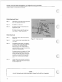
• Internal Transmission Speed Sensor (ITSS)
The transmission speed sensor {see Figure 3-1) gener
ates vehicle speed information in the form of a high
frequency sine wave. The voltage output ranges from
one-fourth (1/4) volt AC peak (.2 volts AC RMS) at 2
MPH to 100 volts (70 volts AC RMS! AC peak at maxi
mum speed. This signal is sent to the vehicle's instru
ment cluster which contains the vehicle speed cir
cuitry.
The speed circuitry consists of solid-state electronic
components that condition and process the speed sig
nal. The signal is converted to a square wave of 1.112
Hertz/MPH which is needed by the cruise control mod
ule. The output frequency is proportional to vehicle
speed.
• Electric Brake Release Sw itches
The combination CRUISE/STOP LIGHT/CONVERTER
CLUTCH switch is used in series with a separately
mounted plunger type cruise release switch (see
Figures 3-2A, 3-2B). When the brake pedal is
depressed, each switch disengages the cruise control
system. The cruise function remains disengaged after
the brake pedal is released.
O utput
Connector
Figure 3-1
6
Internal Transmission Speed Sensor
Figure 3 -2 A
Combination Cruise/Stop Light/Converter
Clutch S w itch
)
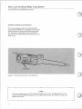
AC Electro-Motor Cruise System Service Manual
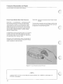
Electronic
Controller
Electric
M otor
Cruise Cable
Connecting Strap
Figure 3-4
Cruise Control Module
(
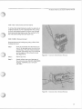
* Electric Clutch Release Switch
On vehicles with manual transmission, a plunger type
clutch switch (see Figure 3-2B) is used in series w ith
the tw o (2) brake switches. When the clutch pedal is
depressed, the clutch switch disengages the cruise
system. The cruise system remains disengaged after
the pedal is released.
• Cruise Control Module
The cruise control module (see Figure 3-4) is mounted
on the engine compartment bulkhead, near the Master
Cylinder. The module replaces both the Electronic Con
trol Module and the vacuum-actuated Servo unit uti
lized in the AC Custom Cruise III cruise system. The
cruise control module which includes an electronic
controller and an electric motor varies the throttle with
each different cruise mode command.
- CAUTION The cruise control module is not dealer serviceable.
DO NOT ATTEMPT TO REPAIR.
Figure 3-2B
Plunger Type Cruise Release Switch
7
Electro-Motor Cruise Block Diagram and System Layout (GMT-400)
AC Electro-Motor Cruise System Service Manual
Component Relationship
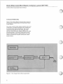
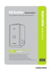
Figure 4-1 is a block diagram showing the component
and operational relationships in the AC Electro-Motor
Cruise System.
The cruise control module, using an electric motor and
an electronic controller (see Figure 3-4), operates the
connecting strap and throttle linkage. The module
receives input signals from the turn signal mode
switches, brake and clutch release switches, and vehi
cle speed circuitry. The Internal Transmission Speed
Sensor (ITSS) generates a high frequency sine wave
which is converted to a square wave by the vehicle
speed circuitry.
Figure 4-1
Block Diagram, Electro-Motor Cruise System
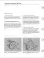
AC Electro-Motor Cruise System Service Manual
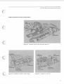
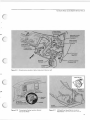
Engine Compartment Cruise Configurations
Cruise
Control Cable
Cruise Cable
S upport Bracket
Cruise
C ontrol M od u le
Accelerator
Control Cable
Figure 4 -2
Installation on LB4 (4.3L), L03 I5.0L), L05 (5.7L)
Accelerator
Cruise
C ontrol M odule
Accelerator
Control Cable
Cruise
Control M odule
Cruise
C ontrol Cable
Cruise Cable
Support Bracket
o r u ia o
Cruise Cable
Support Bracket
Figure 4 -3
Installation on LH6 & LL4 (6.2L, Diesel)
C ontrol Cable
Figure 4-4
Installation on L19 (7.4L)
9
Electro-Motor Cruise Block Diagram and System Layout (GMT-400)
AC Electro-Motor Cruise System Service Manual
Component Location Views
C lutch Release S w itch
Cruise Control
Cruise Control
M ode S w itch
Clutch Pedal
Connector C 3A
Figure 4-5
Cruise Mode S w itch Location: Steering Column
Figure 4 -6
Clutch Release S w itch Location:
Behind Instrument Panel
Cruise
Control
Module
M aster
Cylinder
Connector C4A
Figure 4-7
10
Brake Release/Redundant Release Switch
Location: Behind Instrument Panel
Figure 4-8
Cruise Module Location: Engine Compartment
Bulkhead
AC Electro-Motor Cruise System Service Manual
Brake S w itch
Redundant Cruise
Release S w itc h
Connector
Clutch S w itch
Cruise Control
C onnector
Cruise M odule
Connector C 4A •
■ Instrum ent
Panel (l/P)
Convenience Center
Connector C 5A
Convenience
C e n te r.
Figure 4-9
Wiring Harness Location: Behind Instrument Panel on Left
Speed Sensor
O utput
C onnector
Fuse Block
(Behind Cover)
Belt
Buzzer
for Connector C 5A
in Convenience Center
O utput
Connector
Figure 4-10
Convenience Center Location: Behind
Instrument Panel
Figure 4-11
2-Wheel Drive Speed Sensor Location:
Transmission Note: 4Wkeei DnwSor.soron TransbxCase
11
GMT-400 Cruise Diagnosis and Troubleshooting
AC Electro-Motor Cruise System Service Manual
Preliminary Diagnosis and Inspection
When a vehicle is brought in with a cruise performance
complaint, it is important to carry out a preliminary
diagnosis. This diagnosis should be used to determine
whether the cruise complaint is the result of an actual
cruise system defect - or the result of a problem with
some other vehicle system or component.
Also, some cruise complaints may be a misunderstand
ing by the driver about how the cruise system func
tions. In that case, the operation of the cruise system
should be explained in a manner that the customer
understands. A practical demonstration is very useful,
especially with a similar vehicle which has the same
cruise control system.
If it is decided the cruise system is at fault, perform a
visual inspection of all components in the cruise sys
tem. Cruise performance can be mechanical, electrical,
or combination of the two. Things to check are,..
• Dirty, corroded, or loose ground terminals
• Damaged or mispositioned brake and/or
clutch switches
• Binding or sticking linkage at the throttle body
• Damaged components
• Bare, broken, or disconnected wires
• Adjustment of cruise control module linkage
(see "Cable Adjustment Check," page 26)
If preliminary inspection reveals no solution and the
system is malfunctioning, follow the system diagnostic
chart to isolate the problem (see page 16).
- GOOD ADVICE Verify the problem before you attempt any repairs. Sometimes normal operating characteristics
may be misunderstood as a problem.
12
c
AC Electro-Motor Cruise System Service Manual
Inspection Notes
(
(
--------------------
(
--------------------
c ——
13
GMT-400 Cruise Diagnosis and Troubleshooting
AC Electro-Motor Cruise System Service Manual
Cruise System Functional Check
The procedure below is used to check the operating
modes of the cruise control system. This procedure
should always be used after repair work has been com
pleted on the cruise system. Steps 1-7 and 10 are used
with automatic and manual transmission vehicles,
while steps 8 and 9 are for manual transmission only.
ROAD TEST PROCEDURE
1. Slide the turn signal lever cruise switch to the "O N " position.
2. Check the Low Speed Inhibit: Drive vehicle at 20 MPH. Depress "SET" push
button and release. Cruise control must not engage.
3. Check Set Speed: Drive vehicle at steady speed of 55 MPH. Depress "S E T"
push button completely and release. Cruise control should engage at approxi
mately 55 MPH.
4. Check Brake Release: Depress brake pedal. The cruise control must release
throttle, allowing the vehicle speed to drop. The system must not re-engage
when the brake is released.
5. Check Resume Feature: With the vehicle speed at approximately 45 MPH,
slide the cruise switch momentarily (less than 1 second) to the "R /A " position.
The vehicle should accelerate to approximately 55 MPH.
6. Check Coast Feature: Depress the "S E T" push button and hold. Allow the
vehicle speed to drop to 50 MPH and release push button. Cruise control
should hold vehicle speed at approximately 50 MPH.
7. Check Accelerate Feature: Slide the cruise switch to the "R /A " position and
hold. The vehicle speed should begin to increase. Allow the speed to increase
to 55 MPH and release switch. The cruise control should hold the vehicle at
approximately 55 MPH.
{ITEMS 8 AND 9 ARE FOR MANUAL TRANSMISSION ONLY)
8. Check Clutch Release: Depress clutch. The cruise control must release throttle,
allowing the vehicle speed to drop. The system must not re-engage when the
clutch is released.
9. Slide the cruise switch to the "R /A " position momentarily to resume to 55
MPH.
10. Check Off Switch: Turn the cruise control switch to the "OFF" position. This
must disengage the cruise control system.
Figure 5-1
Chart: Road Test o f Cruise System
AC Electro-Motor Cruise System Service Manual
System Diagnosis
Circuit Operation
The troubleshooting chart on page 16 provides an
organized approach for locating a problem in the cruise
system. Understanding the chart and using it correctly
will reduce diagnosis time and prevent unnecessary
replacement of parts.
With the IGNITION SWITCH in "R U N " {see circuit
schematic, page 18), battery voltage is applied through
the GAGES FUSE to terminal " F " of the cruise control
module. When the slider switch is moved to the "O N "
position, battery voltage is applied to terminal "A " of
the cruise control module connector. If the brake
and/or clutch pedal is not depressed, battery voltage is
present at module terminal "D ". When the slider
switch is moved to the "R /A " position, battery voltage
is applied to terminal " C " of the module. With the
"SET" push button depressed, battery voltage is pres
ent at cruise module terminal "B ". Cruise module con
nector terminal " K " is the speed signal terminal. In
operation, voltage will oscillate between a high of 4 to
5 volts and a low of near ground. Cruise module termi
nals "G ", "H ", and " J " are not used. Ground is at
module terminal "E".
HOW TO USE CHART
Disconnect the cruise control module connector (see
Figure 6-1, page 20, "Task One") and perform the
troubleshooting steps at the connector. A high imped
ance digital voltmeter is used to make the checks.
* If the results of the test step are not cor
rect, go to "THINGS TO CHECK" box for
that test step.
* If the results of a test step are correct, go
to next step.
{See GMT-400 Cruise Diagnostic Chart for reference to Figures 5*2 & 5-3, pages 16 & 17.)
Terminal ” B "
Green W ire
” K " Terminal
(Vehicle Speed Input)
“ F " Terminal
(Ignition)
Terminal " C "
Yellow W ire
Figure 5-2
Voltmeter Hookup
Figure 5-3
Cruise Mode S w itch Connector (C3A)
15
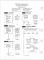
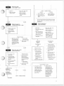
GMT-400 Cruise Diagnostic Chart
(CRUISE SYSTEM TROUBLESHOOTING WITH A
HIGH IMPEDANCE DIGITAL VOLTMETERI
r
TROUBLESHOOTING HINTS
1. Cruise fuse (labeled "Gages" in (use
block) is OK if seat belt buzzer is working.
and Cruise Module connector C4A for
proper connection (see Figures 4-8,4-9).
2. "Speedo" fuse is OK if speedometer or
odometer is operating.
Check that cruise module linkage is
connected and moving freely.
3. Check Convenience Center connector C5A
Check cruise cable adjustment (see page 26).
i____
Checks for an open in
cruise power circuit
Checks for a short in
cruise control lever
J__________
r
• Ignition off.
NOTES
1. Never attempt to back
probes sealed
connector.
• Disconnect connector
C4A from cruise
module. See circuit
schematic, page 18.
2. Never attempt to insert
meter leads into
terminal slots.
• Ignition on.
• Measure voltage at
terminal F of C4A to a
good ground.
|
THINGS TO CHECK
Measure voltage at
terminals B and C of
C4A to ground with
cruise slider switch
"O N " and ignition
switch on.
1-
1
0 VOLTS
12 VOLTS
I
Disconnect connector
C3A. Measure voltage
again at terminals A, 8,
C, and D of connector
C4A.
• If all terminals read
zero volts, replace
cruise control lever.
L
-------------------------
. 1.
I
0 VOLTS
AT B AND C
12 VOLTS
AT 8 OR C
I
REPLACE CRUISE
CONTROL LEVER
Checks for resistance of
cruise system ground wire
• If one or more
terminals read 12
volts, problem is in
wiring harness.
Checks for an open in ' ’BRAKE" circuit
or "ON/OFF" circuit
r*'
With ohmmeter,
measure resistance of
BLK/WHT wire (4501
from terminal E of C4A
to engine block ground
stud. See circuit
schematic.
THINGS TO CHECK
t. Check "Gages” fuse
2. Check PNK wires
(39A, 39B) and
PNK'BLK wires (39A.
39C) for open. See
circuit schematic.
3. Check connector C5A
at Convenience Center
for contaminants (oil,
grease, dirt) and for
proper contact.
Measure voltage at terminals A and D of C4A to ground
with cruise slider switch ‘'O N" and ignition switch on.
12 VOLTS
AT A AND D
0 VOLTS
AT A AND D
0 VOLTS
ONLY AT D
RESISTANCE
GREATER THAN 1 OHM
Checks for a short in
cruise wiring harness
Measure voltage at
terminals A, B, C, and D
of C4A to ground with
cruise slider switch
"OFF” and ignition on.
r
THINGS TO CHECK
THINGS TO CHECK
Check for 12 volts at
terminal A of female
half of connector C3A.
and B of male half of
C3A with cruise switch
"O N ". See Figure 5-3
• If zero volts, check
for open in PNK wire
(39C).
• If open, replace
cruise control lever.
Check continuity
between terminals A
1 Check engine block
ground stud for a clean
and tight connection.
2. Check condition of
BLK/WHT wire 14501
from terminal E of C4A
to engine block ground
stud.
(0 VOLTS ONLY AT D)
Check for open or misadjusted brake switches
or clutch switch.
2. Check for open in
brake/clutch switch
wiring from splice S2A
to terminal D or C4A.
(0 VOLTS ONLY AT A)
12 VOLTS ATONE
OR MORE TERMINALS
TO STEP 4
16
c
3. Check for open in GRA
wire (397B).
1. Check for an open in GRA wire (397A).
0 VOLTS AT
ALL TERMINALS
<
0 VOLTS
ONLY AT A
(0 VOLTS AT A AND D)
RESISTANCE
LESS THAN 1 OHM
C
-TO STEP 6
c
Checks for an open
in ’'SET/COAST" circuit
• Ignition on
STEP 8
* Push cruise "SET" push
button in and hold.
• Move cruise slider
switch to "ON".
2. Check for open on
BRN/WHT wires (437,
437A1.
If wires are OK see electrical section of Division
Service Manual for additional speed sensor
diagnostics.
0 VOLTS
Checks for operation of
cruise control module
Checks for an open in
"RESUME/ACCEUR/A)" circuit
• Start engine
Hold cruise slider switch
in "R.'A" position.
• Move cruise slider switch
to'■O FF’.
Measure voltage at
terminal C of C4A to
ground.
• Move cruise switch to
"ON" and then wait at
least 3 seconds before
doing next step.
• Fully depress and hold
brake pedal.
THINGS TO CHECK
)
2. Check for open in DK
BLU wire (84>.
ENGINE RPM
INCREASE
0 VOLTS
THINGS TO CHECK
Problem is intermittent.
Chacks for an open or short
in vehicle speed circuit
THINGS TO CHECK
• Also check ground
terminals for con
taminants and proper
contact.
(see ground check below!
2. Check for open in DK
GRN wire 183!
1
NO ENGINE RPM
INCREASE
THINGS TO CHECK
Check that cruise mod
ule linkage is connected
and operating freely.
Check linkage adjust
ment. See pages
26-27
Check terminals in con
nectors C3A, C4A,
C5A for contaminants
(oil, grease, dirt! and for
proper contact,
isee ground check below)
• If OK replace cruise
control module.
0 VOLTS
"GOOD GROUND" CHECK
J
1
12 VOLTS
I
J
♦ After 10 seconds,
release brake pedal white
still holding "R /A" and
"SET" switches and
listen for momentary
engine RPM increase.
• If open, replace
cruise control lever.
• Spin drive wheels by
hand.
VOLTAGE VARYING
BETWEEN 0
AND 12 VOLTS
* Check connectors
and wire terminals
for contaminants (oil,
grease, dirt) and for
proper contact.
1. Disconnect C3A and
check continuity
between terminals A
and C of mate half with
cruise switch in''R. A"
position.
* Ignition on. raise vehicle.
put transmission in
neutral.
• Hold cruise slider switch
in''R /A '' position.
I
CRUISE MODULE
IS OK
I
• Connect voltmeter
across pins F and K of
connector C4A. See
Figure 5-2
• Push cruise "SET" push
button in and hold
• If open, replace
cruise control lever.
12 VOLTS
• Put voltmeter on DC
voltage scale.
12 VOLTS
1. Check for short to
ground on BRN/WHT
wires (437,437A).
1. Check "Speedo" fuse.
I
1. Disconnect connector
C3A and check con
tinuity between termi
nals B and D of male
half wrth "SET" push
button depressed. See
Figure 5-3
THINGS TO CHECK
0 VOLTS
* Measure voltage at
terminal Bof C 4Ato
ground.
12 VOLTS
._L.
.L .
r
RECONNECT
CRUISE MODULE
CONNECTOR C4A
STEP 8 - THINGS TO CHECK
A. Turn ignition on. move
cruise slider switch to
"ON" position. Perform
voltage check between
suspected bad cruise
ground and engine block.
Any voltage means
ground is bad.
B. If step "A" fails to
locate problem, run a
second ground wire
from engine block to pin
E of cruise module. If
second wire corrects
problem, then recheck
ground path (450) for
problem. (Remove
second wire after
troubleshooting is
completed.!
-TO STEP 9
17
GMT-400 Cruise Diagnosis and Troubleshooting
AC Electro-Motor Cruise System Service Manual
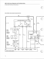
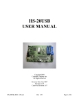
Electro-Motor Cruise System Circuit Schematic
39A
BPN K
IGN.
C R U IS E CO N TRO L M ODULE
18
BRAKE
INPUT
ON/OFF
INPUT
S 1 A (S P U C E I
SET CO A ST
INPUT
RESUM E/ACCEL
INPUT
V EH ICLE
SPEED INPUT
GROUND
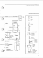
AC Electro-Motor Cruise System Service Manual
Schematic Symbol Explanation
S3A (SPLICE)
39 C
8 PNK/BLK
____ ! —
• 2 0 AMP]
♦
|
S g a g es!
c
FU SE I
□
FUSE
BLOCK
FNTIR F
COM PONENT
SHOW N
J
PART OF A
a
C O M PO NFNT
•
SH O W N
HOT IN RUN
SPEED SENSOR
AT TRANSMISSION
39 E
8 PNK/BLK
C ON N EC TOR
A\
A T T A C H E D TO
COM PONENT
4 0 0 BY
8 YEL
401 BY
8 PPL
FGMALE
T E R M IN A L
\
BULKHEAD
CONNECTOR
401
8 PPL
C4A
400
8 YEL
B1 3
/,
A
M ALE
T t HM IN AL
r
t
A 10
1-------------<
\<—
IGN.
GAGE
437A
I BRN^WHT
A 16
I
i—
CRU ISE SPEED
SIGNAL OUTPUT
B15
;
!
'
SPEED INPUTS
IN S T R U M E N T
C LU STER
IN S U L A T IO N COLO R
j
45C]
B B L K 'W H l
IS L A B F I FD
SPLICES ARE S H O W N
A N D N U M B ER ED
C IR C U IT NUMBER IS
S H O W N TO HELP IN
T R A C IN G C IR C UITS
450
B B L K /W H T |
A W A V V LINE
r —
GROUND
«
i
i
M F A N S A WIRE
IGN
SPEEDO
’ 1S T O BE C O N TIN U E D
1
£
IN D IC A T F S T H A T
THE CIR C UIT BY IS
! 4 5 0 C .8 BLK/WHT
N O T S H O W N IN
C O M PLE TE D E T A IL
i
i
■
J
S4A (SPLICE)
^
SEE GROUND
DISTRIBUTION
4 5 0 8 BLK/WHT
J
C]
T
AMP
SPEEDO
FUSE
IA N U A L
^
IN DIVIS40IN
SERVICE M A N U A l
BULKHEAD
CONNECTOR
W IR F C H OIC ES
FOR O P TIO N S
OR DIFFERENT
M O D F LS ARE
S H O W N AN D
1„
I
k
i
|
£
™
D
IST R IB U T IO N
D'ST
E N G INF
B LO C K GR OU N D
I
'f '
I
W
*
|
BUT IS C O M PLE TF
^- s eSEE
T aGR
f OU N D
I
a O R A .-filK
43?
a BRN.'WHT
TO ENGINE BLOCK
SE E GROUND DISTRIBUTION
IN 0IV ISI0N SER V IC E MANUAL
LABELED
I
450
8 BLKi’WHT
T W O OR MORE
TER M IN A LS IN TH E
HOT IN RUN
S A M E C O N N EC TO R RCIDY
D ASH ED LINE SH O W S
C ON VEN IE N CE
CENTER
[
A P H Y S IC A L C O N N EC T IO N
0ET W F F N PARTS
IS A M E c o n n e c t o r :
19
Connector Disassembly and Repair
AC Electro-Motor Cruise System Service Manual
Cruise Control Module Metri-Pack Connector
TASK ONE: Removal o f connector from Cruise Control
Module
Metri-Pack — or weatherproof — connectors provide
environmental protection for the electrical circuits.
This protection consists of a moisture-proof rubber
seal between the tw o connector halves and rubber
cable seals attached to each terminal. The terminals
and the cable seals are secured by a plastic terminal
retainer. (Note: NEVER ATTEMPT TO BACK PROBE
SEALED CONNECTORS.)
To remove the connector, use your finger to pull up and
outward on the connector's locking tab. Not much pull
is required for removal (see Figure 6-1).
If a Metri-Pack connector requires repair, do not replace
the Metri-Pack parts with other types of connectors
and terminals. Also, do not omit either the large seal or
the cable seals when making a repair.
Instruction in the disassembly, repair, and assembly of
the Metri-Pack connector follows. Only perform those
tasks necessary to make the repair.
Figure 6-1
Cruise Module Connector Removal
- NOTE To lessen repair work Time, use terminal pick tool (Kent-Moore, P/N J-35689-A), (Burroughs, P/N
BT-8446), or equivalent.
20
AC Electro-Motor Cruise System Service Manual
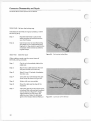
TASK TWO: Remove the terminal retainer
To remove the terminal retainer, position a wide pick or
small screwdriver at a 45° angle between the connec
tor body and terminal retainer and then exert enough
force to slip terminal retainer over the locking nib. Do
this with both locking nibs (see Figure 6-2),
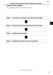
TASK THREE: Remove the lead
Depress the terminal locking tang using a Metri-Pack
Terminal pick tool:
Step 1
Push the metal pick into the narrow por
tion of the terminal cavity from the front
until it stops. The pick should be placed
between the locking tang of the terminal
and the plastic of the connector body
(see Figure 6-3).
Step 2
Pull the pick out.
Step 3
Gently pull the lead out of the back of
the connector body. (NEVER USE FORCE
TO PULL TERMINAL OUT OF CON
NECTOR.)
Figure 6-3
Connector (C4A! Terminal Removal
21
Connector Disassembly and Repair
AC Electro-Motor Cruise System Service Manual
(
TASK FOUR: Re-form the locking tang
If the lead and terminal are in good condition, re-form
the locking tang:
Step 1
Hold the lead firmly to prevent the
splice between the terminal and the
wire from flexing.
Step 2
Use the pick tool to bend the locking
tang back into its original shape (see
Figure 6-4). Also, check to see that the
remainder of the terminal is still in its
original shape.
TASK FIVE:
Make the repair
When making a repair, use the correct types of
terminals, wires, and seals.
Step 1
Cut the wire immediately behind the
cable seal.
Step 2
Slip the new cable seal onto the wire
and push it back out of the way.
Step 3
Strip 5.0 mm (.2 inches) of insulation
from the wire.
Step 4
Crimp the new terminal over the wire
(core crimp) as shown in Figure 6-5.
Step 5
Solder with rosin core solder.
Step 6
Move the cable seal to edge of the
insulation.
Step 7
Crimp the grips at the end of the termi
nal around the cable seal and insulated
wire as shown in Figure 6-5. Apply
slight pressure for this crimp. (For
splicing wires, follow the directions
given in the Division Service Manual.)
22
Figure 6-5
Connector (C4A) Terminal
AC Electro-Motor Cruise System Service Manual
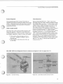
TASK SIX : Insert the lead
TASK SEVEN; Replace the terminal retainer
Before inserting the lead, make certain that the termi
nal is correctly shaped. Then gently insert the lead
from the back. The terminal should stop or "catch"
about halfway through the connector body. Gently
push back and forth on the lead to be sure the terminal
is held in place in both directions. If the terminal easily
pushes or pulls out, review task four; "Re-form the
locking tang."
Replace the terminal retainer by firmly pushing on the
retainer until both locks snap into place.
Inspection Notes
23
Cruise Control Cable Installation and Adjustment Procedures
AC Electro-Motor Cruise System Service Manual
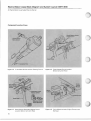
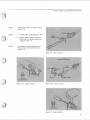
Cable Installation
Step 1
Attach cable bead to cruise module strap
end fitting and remove retainer (Figure
7-1).
Strap
Step 2
A. Pull cruise cable engine end fitting
until cable is snug (Figure 7-2).
B. Turn cruise cable strap end fitting to
straighten strap. Strap should be flat
and vertical. (Note: Strap must not be
twisted, as shown in Figure 7-2.)
Step 3
Figure 7-1
Cable Installation
Slide cable conduit over strap and install
tangs in cruise motor housing (Figure
7-3).
Strap
Correct
Cable
Cable Engine
Incorrect
24
Figure 7-2
Cable Installation
Figure 7-3
Cable Installation
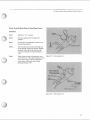
AC Electro-Motor Cruise System Service Manual
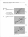
Step 4
Install cable conduit in engine bracket
(Figure 7-4).
Step 5
A. Unlock cable conduit (Figure 7-5A)
8. Attach cable engine end fitting to
lever stud and install retainer clip
(Figures 7-5B, 7-7).
Step 6
Lock cable conduit by pushing down
firmly on lock until it locks in place
(Figure 7-6).
Figure 7-4
Cable Installation
Gasoline (TBI) Lever
V ie w (A)
Unlocked Position
Figure 7-5A
Cable Installation
Stud
Figure 7-5B
Figure 7-6
Cable Installation
Cable Installation
25
Cruise Control Cable Installation and Adjustment Procedures
AC Electro-Motor Cruise System Service Manual
Cable Adjustment Check
Diesel Lever
Step 1
Disconnect cruise cable engine end from
lever stud (Figures 7-5B, 7-7).
Step 2
Pull lightly on cable end.
Step 3
If cable end does not extend forward,
adjustment is OK,
If cable end does extend forward, per
form steps in "Cable Adjustment."
Cable Adjustment
Step 1
Reconnect cable to lever stud (Figures
7-5B, 7-7).
Step 2
Unlock cable conduit engine fitting (Fig
ure 7-5A).
Step 3
For gasoline (TBI) engines, turn ignition
off. Move cable conduit (see Cable Con
duit, Figure 7-4) until throttle plate
begins to open. Then move conduit in
opposite direction enough to return throt
tie plate to closed position.
Figure 7-7
Cable Adjustment
For diesel engines, turn ignition off. Move
cable conduit until injector pump lever
moves from idle stop screw. Then move
conduit in opposite direction enough to
return lever to idle stop screw (Figure
7-7).
Step 4
While holding cable conduit, push down
firmly on cable conduit lock until it locks
in place (Figure 7-6).
- NOTE DO NOT RELEASE HAND GRIP FROM CABLE CONDUIT UNTIL STEP 4 IS FINISHED.
26
AC Electro-Motor Cruise System Service Manual
Cruise Control Mode Switch (Turn Signal Lever)
Installation
Step 1
Rotate to "L O " position.
Step 2
Put turn signal switch in right turn
position.
Step 3
For tilt column installation, column is to
be in full up position.
Step 4
Insert music wire tool into opening and
route through column as shown. Attach
terminal to tool and pull wire through
column until slack is removed {Figure
7-8).
Step 5
Slide cruise control wire protector over
wire from lever. Then slide protector over
nib on main wire protector until lower
end is even with lower end of main
protector {Figure 7-9).
Music
Wire
Column
Figure 7-8 Cable Adjustment
Route Cruise W ire
Below and Parallel
to W iper
Wiper SW Leads
Cruise
Wire
Cruise
Control Wire
M ain Protector
Figure 7-9 Cable Adjustment
27
AC Electro-Motor Cruise System Service Manual
Inspection Notes
28
o
O
o
J
AC Spark Plug Division,
General Motors Corporation
1300 N. Dort Highway
Flint. Michigan 48556
U.S.A.
Australia
England
AC Spark Plug O verseas C o rporation
499 S t Kilda Road, 1 5 th Floor
M elbourne. 3 0 0 4 , V ictoria
Australia
AC Spark Plug O verseas C o rporation
P.O. Bo* 3 3 6 — Sentry House
5 0 0 A ve bury Blvd.
C entral M ilto n Keynes
M ilto n Keynes M K 9 2NH, England
Franco
AC Spark Plug
General M oto rs France
5 6 -6 8 Avenue Louis Roche
92231 G enneviiliers. France
Japan
AC Spark Plug
A s ia /P a c ific Region
GMOC Tokyo Zone
R oppongi-Fuji B u ilding
5th Floor
2 -6 Nishiazabu
3-C hom e M in a to ku
Tokyo 106, Japan
Ita ly
AC Spark Plug
G eneral M oto rs Italia S.p.A.
Via S. Q uintino, 28
Palazzo G alileo
1-10121
Torino. Italy
Germany
AC Spark Plug
General M oto rs S ervice G mbH
Eisertstrasse 2. Postfach 1 5 0 7
D -6 0 9 0 Russelsheim
Federal R e public o f Germ any