1
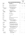
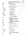
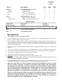
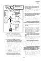
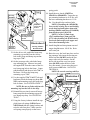
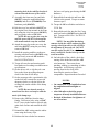
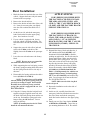
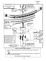
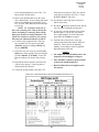
52800/52800MX/
52800MXR
Revised
12.18.08
2360 Boswell Road
Chula Vista, CA 91914
Phone
619.216.1444
Fax
619.216.1474
E-Mail
[email protected]
PRO COMP SUSPENSION
Suspension Systems that Work!
IMPORTANT: On V-10 equipped vehicles be sure to check the clearance between the driveshaft and the exhaust. If there is contact take the vehicle to a qualified
exhaust shop for modification.
Part #
52800B/52800BMX
2008-2009
Ford Super Duty
4WD F250-F350
Stage 1 Lift Kit
with Add-A-Leaf
This document contains very important information that includes warranty information and instructions for
resolving problems you may encounter. Please keep it in the vehicle as a permanent record.
Box 1 of 4-PN 52800B/52800BMX/52800MXR-1
Part #
Description
Qty.
52800/52800MX/
52800MXR
Revised
12.18.08
Illus.
Page
90-3822
SWAY BAR SPACER
1
8
11
90-3823
STEERING STABILIZER BRACKET
1
8
11
90-3812
TRACK BAR DROP BRACKET
1
1,3,9
6,7,11
90-6369
70-0563001800
72-05600100816
73-05600830
HARDWARE PACK: Track Bar Drop
9/16” X 3” HEX BOLTS GR. 8
9/16” STOVER NUTS ZINC
9/16” WASHER SAE GR. 8
1
3
3
6
3
3
3
7
7
7
90-2357
SWAY BAR END LINK
2
-
-
90-6242
600026
113600020
HARDWARE PACK: Sway Bar
3/4” HOURGLASS BUSHING
SLEEVE
2
2
2
-
-
FD-700
PITMAN ARM
1
1
6
95-150F
1 1/2” LIFT BLOCK
2
10
14
95-100F
1” LIFT BLOCK
2
-
-
13-90180
U-BOLT
4
10
14
20-65471
HARDWARE PACK: 5/8” Hi nuts & Washers
1
10
14
90-2511
BUMP STOP SPACER
2
7
10
90-6390
70-0436501800
73-04300034
72-04300100816
HARDWARE PACK: Bump Stop
7/16” X 6 1/2” USS GR. 8 HEX BOLT
7/16” SAE FLAT WASHER
7/16” USS GR.8 STOVER NUT
1
2
4
2
7
7
7
10
10
10
90-6570
90-2413
HARDWARE PACK: Sway Bar
SWAY BAR END LINK SPACER
1
2
-
-
90-6042
45359
60859H
HARDWARE PACK:Rear Sway Bar Links
5/8” RUBBER HOURGLASS BUSHING
5/8” O.D. X 12mm I.D. X 1.480” SLEEVE
2
4
4
-
-
90-6572
.120C750HCS1Z
.120CNNEZ
.120NWHDY
HARDWARE PACK:Rear Sway Bar Links
12mm-1.75 X 70mm HEX BOLT GR. 10.9
12mm-1.75 NYLOCK NUT
12mm HARDENED FLAT WASHER
2
4
4
8
-
-
90-2446
REAR SWAY BAR END LINKS
2
-
-
96-5002
PITMAN ARM TOOL
1
2
7
90-6595
HARDWARE PACK: Pitman Arm Tool
Thread locker
7/16" X 1 1/4" GR. 8 HEX BOLT
7/16" FLAT WASHER
7/16" NYLOC NUT
1
1
1
1
2
2
2
2
7
7
7
0431251800
04300030
04300100512
2
52800/52800MX/
52800MXR
Revised
12.18.08
Box 2 of 4-PN 52800B/52800BMX/52800MXR-2
Part #
Description
Qty.
Illus.
Page
90-6386
90-2507
HARDWARE PACK: Radius Arm
RADIUS ARM SPACER TUBE
1
2
4
8
90-3166
RADIUS ARM DROP SIDE PLATE
2
4,5,6
8,9
90-3167
RADIUS ARM DROP SIDE PLATE (With Notch)
2
4,5,6
8,9
90-6370
70-0751501800
72-075100816
73-07500830
70-0755001800
70-0431501800
72-043100816
73-04300830
HARDWARE PACK: Radius Arm Drop
3/4” X 1 1/2” HEX BOLTS GR. 8
3/4” STOVER NUTS
3/4” WASHERS SAE GR. 8
3/4” X 5 HEX BOLTS GR. 8
7/16” X 11/2” HEX BOLTS GR.8
7/16” STOVER NUTS
7/16” WASHERS SAE GR. 8
1
4
6
12
2
8
8
4
4
4
4
5
5
8
8
8
8
9
9
16
5
9
90-6569
90-1080
90-1081
90-1082
90-6013
70-04322501800
73-04300042
HARDWARE PACK: Driveline Shim
3/8” Driveline Shim
1/4” Driveline Shim
1/8” Driveline Shim
HARDWARE PACK: Driveline Shim
7/16” x 2 1/4” USS Grade 8 Bolt
7/16 USS Hardened Washer 2
1
2
2
2
1
2
2
-
-
2
2
-
-
2
2
-
-
Box 3 of 4-PN 52800B-3
926553
932008
FRONT SHOCKS
REAR SHOCKS
(OR) Box 3 of 4-PN 52800BMX-3
MX6154
MX6018
MX6 FRONT SHOCKS
MX6 REAR SHOCKS
(OR) Box 3 of 4-PN 52800BMXR-3
MX6065R
MX6069R
MX6R FRONT SHOCKS
MX6R REAR SHOCKS
2
2
-
-
90-6518
600026
113600020
HARDWARE PACK: MX6R Front Shocks
3/4” HOURGLASS URETHANE BUSHING
SLEEVE
2
1
1
-
-
690002
1” SHOCK MOUNT ADAPTER: Front Shocks
2
-
-
63012
EXTERNAL RESERVIOR MOUNTING KIT
4
-
-
5242
24” LIMIT STRAP
2
-
-
90-6573
70-0503751800
72-050100512
73-05000034
72-062100512
73-06200034
HARDWARE PACK: Limit Straps
1/2” X 3 1/4” GR. 8 HEX BOLT
1/2” NYLOCK NUT
1/2” SAE FLAT WASHER
5/8”NYLOCK NUT
5/8” USS FLAT WASHER
1
2
2
6
2
2
-
-
Box 4 of 4-PN 52800B/52800BMX-4
13150-1
ADD-A-LEAF
2
9
13
13150-2
ADD-A-LEAF
2
9
13
3
52800/52800MX/
52800MXR
Revised
12.18.08
Part #
Description
Qty.
Illus.
Page
90-7130
98-00300-1
98-003002
97-716
8771-1
HARDWARE PACK: Add-A-Leaf
3” SPRING CLAMP
3” SPRING PLATE
7/16”X 4 1/2” CENTER BOLT
7/16”GR. 8 CENTER BOLT NUT
1
4
4
2
2
9
9
9
9
13
13
13
13
90-6337
97-165
72-01015008812
HARDWARE PACK: Add-A-Leaf
10MM X 165MM CENTER PIN
10MM-1.5 NUT (CENTER BOLT NUT)
1
2
2
9
9
13
13
Special Tools:
Pitman Puller
Tie Rod Separator
Snap-On PN
Ford PN
CJ1119B
T64P-3590-F
The following parts are used in conjunction with this kit and must be purchased separately.
24514
COILS GASOLINE ENGINE
1
-
-
COILS DIESEL ENGINE
1
-
-
OR
24515
Introduction:
♦
This installation requires a professional mechanic!
♦
We recommend that you have access to a factory service manual to assist in the disassembly and reassembly of your
vehicle. It contains a wealth of detailed information.
♦
Prior to installation, carefully inspect the vehicle’s steering and driveline systems paying close attention to the tie rod
ends, ball joints, wheel bearing preload, pitman and idler arms. Additionally, check steering-to-frame and suspensionto-frame attaching points for stress cracks. The overall vehicle must be in excellent working condition. Repair or replace all worn or damaged parts!
♦
Read the instructions carefully and study the illustrations before attempting installation! You may save yourself a lot of
extra work.
♦
Check the parts and hardware against the parts list to assure that your kit is complete. Separating parts according to the
areas where they will be used and placing the hardware with the brackets before you begin will save installation time.
♦
Check the special equipment list and ensure the availability of these tools.
♦
Secure and properly block vehicle prior to beginning installation.
♦
ALWAYS wear safety glasses when using power tools or working under the vehicle!
♦
Use caution when cutting is required under the vehicle. The factory undercoating is flammable. Take appropriate precautions. Have a fire extinguisher close at hand.
♦
Foot pound torque readings are listed on the Torque Specifications chart at the end of the instructions. These are to be
used unless specifically directed otherwise. Apply thread lock retaining compound where specified.
♦
Please note that while every effort is made to ensure that the installation of your Pro Comp
lift kit is a positive experience, variations in construction and assembly in the vehicle manufacturing process will virtually ensure that some parts may seem difficult to install. Additionally, the current trend in manufacturing of vehicles results in a frame that is highly flexible
and may shift slightly on disassembly prior to installation. The use of pry bars and tapered
punches for alignment is considered normal and usually does not indicate a faulty product.
However, if you are uncertain about some aspect of the installation process, please feel free to
call our tech support department at the number listed on the cover page. We do not recommend that you modify the Pro Comp parts in any way as this will void any warranty expressed or implied by the Pro Comp Suspension company.
4
52800/52800MX/
52800MXR
Revised
12.18.08
Please Note:
⇒ Front suspension and head light realignment is necessary!
⇒ Speedometer and ABS recalibration will be necessary if larger tires (10% more than stock diameter) are in-
stalled.
⇒ IT IS ADVISABLE THAT YOU HAVE HELP AVAILABLE WHEN INSTALLING THIS KIT. SOME
COMPONENTS ARE HEAVY AND AWKWARD. AN ADDITIONAL SET OF HANDS IS GOOD INSURANCE AGAINST INJURY!
Important!
Due to differences in manufacturing, dimensions and inflated measurements, tire
and wheel combinations should be test fit prior to installation. Tire and wheel
choice is crucial in assuring proper fit, performance, and the safety of your Pro
Comp equipped vehicle. For this application, we recommend a wheel not to exceed
10” in width with a maximum backspacing of 5 3/4” must be used. Additionally, a
quality tire of radial design, not exceeding 37” tall X 13.50” wide is also
recommended. Violation of these recommendations will not be endorsed as
acceptable by Pro Comp Suspension and will void any and all warranties either
written or implied.
Before You Begin:
⇒ Read the instructions and study the illustrations before attempting the installation.
⇒ Separating the parts according to the areas where they will be used and placing the hardware with the
brackets before you begin will save installation time.
⇒ Check the parts and hardware against the parts list to assure that your kit is complete.
⇒ ALWAYS wear safety glasses when using power tools or working beneath your vehicle.
⇒ A pitman arm removal tool and tie rod separating tool are required to perform the installation. See the
special tools at the top of page 4.
⇒ Always use NEW cotter pins on re-assembly! (These items are NOT supplied)
Optional Equipment Available from your Pro Comp Distributor!
52460B: FRONT DUAL SHOCK KIT,
22518 (x2): LEAF SPRINGS,
95-400SD (x2): 4” LIFT BLOCK,
95-550SD (x2): 5 1/2” LIFT BLOCK,
LIGHTS,
50191: U-BOLT KIT,
599: ALIGNMENT CAM KIT,
72400: TRACTION BARS,
72099: TRACTION BAR MOUNTING KIT
219567: DUAL STEERING STABILIZER
99-400: 4 DEGREE REAR AXLE SHIM KIT
Also, check out our outstanding selection of Pro Comp tires
to compliment your new installation!
5
52800/52800MX/
52800MXR
Revised
12.18.08
Front Installation:
1. Position your vehicle on a smooth, flat,
hard surface (i.e. concrete or asphalt).
Block the rear tires and set the emergency
brake.
2. Measure and record the distance from the
center of each wheel to the top of its
fender opening. Record below.
LF:
RF:
LR:
RR:
3. Place the vehicle in neutral. Place your
floor jack under the front axle and raise
the vehicle. Place jack stands under the
frame rails and lower the frame onto the
stands. Remove the jack and place the
vehicle back in gear, set the emergency
brake, and place blocks both in front and
behind the rear wheels.
4. Remove the track bar bolt from the driver
side frame mount. Save this hardware for
re-use.
arm. The threads of the sector shaft and
the Pitman arm retaining nut must be
cleaned of all factory dry adhesive.
IMPORTANT!: THE ENTIRE INSTALLATION PROCESS MUST BE DONE WITH
HAND TOOLS TO ENSURE PROPER INSTALLATION. DO NOT USE IMPACT
TOOLS.
11. Install new pitman arm on sector shaft.
Oil the sector shaft threads to ensure a
proper torque reading. Install Pitman arm
retaining nut and tighten until snug. See
Illustration 1.
12. Insert the key and unlock the steering
wheel.
13. Install the Pitman arm torque tool (905002) to the Pitman arm using one of the
previously removed OE 14mm track bar
bracket outer retaining bolt and nut plate.
See Illustration 2.
14. Secure the torque tool (90-5002) to the
existing hole in the frame crossmember
5. Remove the cast track bar mount on
driver side of frame. Save the bolts and
pal nuts. Hardware will be reused.
6. Unbolt the sway bar from the sway bar
end links on both sides of the vehicle.
Unbolt and remove the sway bar end links
from the vehicle. Save the hardware for
reuse.
7. Unbolt the sway bar from the frame of the
vehicle. Save the hardware for reuse.
Illustration 1
Pitman Arm Assembly
Sector
Shaft
Nut
90-3812
Track Bar
Drop
Bracket
8. If the vehicle is equipped with a factory
steering stabilizer unbolt it from the frame
mounting bracket.
Cotter Pin
9. Remove the cotter pin and nut from drag
link. Save the nut for reinstallation. Use
a tie rod separator to separate drag link
from Pitman arm.
10. Remove the sector Pitman arm retaining
Drag
Link
nut and save for reinstallation. Use a Pitman arm puller to remove the OE pitman
6
FD-700
Pitman
Arm
52800/52800MX/
52800MXR
Revised
12.18.08
Frame Crossmember
Illustration 2
Existing
Hole
Pitman Arm Torque Tool
Pitman
Arm
OE 14mm Track
Bar Retaining Bolt
Pitman
Arm
Frame
Crossmember
OE 14mm
Nut Plate
90-5002 Torque Tool
using the supplied 7/16” X 1 1/4” bolt
and hardware. See Illustration 2.
NOTE: The steering wheel may need
to be turned in order for the hole in the
torque tool and the frame crossmember
to line up. Once the bolts are tightened
the torque tool will align it’s self properly.
NOTE: The use of the torque tool is
to keep the Pitman arm from moving
right or left, but
Illustration 3
OE Pal Nut
90-5002
Torque Tool
Track Bar Bracket Assembly
OE Pal Nut
7/16” X 1
1/4” Bolt
allow for movement up the sector shaft.
If you do not have this tool, a length of
chain or a flat bar with two holes is a
suitable replacement.
15. Torque the Pitman arm retaining nut to
375 ft./lbs.
16. With the torque tool (90-5002) still in
place remove the pitman arm retaining
nut. The threads of the sector shaft and
the Pitman arm retaining nut MUST be
cleaned using brake cleaner or another
suitable method to remove the previously
applied oil.
17. Use the entire supplied thread locking
compound to thoroughly cover the entire
surface of the threads on the Pitman arm
retaining nut.
18. Reinstall the Pitman arm retaining nut to
the sector shaft and torque to 350 ft./lbs.
NOTE: Whether re-using the existing pitman arm retaining nut or replacing with a new nut, the supplied locking
compound must be used.
(3) 9/16”
X 3” Gr. 8
Bolts
19. Unbolt and remove the Pitman arm torque
tool (90-5002) from the vehicle.
90-3812 Track
Bar Drop
Bracket
OE Bolts
NOTE: Save this Pitman arm torque
tool to add to your toolbox for any future
Pitman arm installations.
OE Bolts
20. Install track bar drop bracket (90-3812)
using (3) 9/16” X 3” and (2) OE bolts.
Use thread locker on the bolts. Torque
OE the bolts to 129 ft. lbs. and the 9/16”
7
52800/52800MX/
52800MXR
Revised
12.18.08
Illustration 4
Front Radius Arm Drop
Bracket Assembly
3/4” X 1 1/2”
Gr. 8 Bolt
3/4” X 1 1/2”
Gr. 8 Bolt
Frame Pocket
3/4” X 5”
Gr. 8 Bolt
The Notched
Bracket Goes
on the Bottom
3/4” Stover
Nut and
Washers
90-3166
Radius
Arm Drop
Bracket
90-2507
Spacer
Tube
bolts to 110 ft. lbs. See ILLUSTRATION
3.
90-3167
Radius
Arm Drop
Bracket
clips from the frame.
21. Unbolt the front brake line bracket from
the lower spring perch. Save hardware
for reuse.
26. Place a jack under the pinion or radius
arm. On both sides remove the rear bolts
holding the radius arms to the frame of
the vehicle.
22. Unbolt and unclip the ABS wiring connected to the radius arm. Save hardware
for reuse.
27. Carefully rotate both radius arms down to
provide adequate space to install the new
drop brackets.
23. On the driver side, unclip the axle vent
line from inside the frame.
28. On both sides of the vehicle, assemble the
radius arm drop side plates (90-3166 on
top) and (90-3167, with the notch in it,
on the bottom) and bolt radius arm drop
to the frame. Use the supplied 3/4” X 1
1/2” bolts in the front hole with the heads
of the bolts facing out. Do not torque at
24. On the passenger side unclip the axle hub
vacuum line from inside of the axle bump
stop plate.
25. Remove the transfer case skid plate. Also
remove the rubber grommets, sleeves and
8
52800/52800MX/
52800MXR
Revised
12.18.08
Illustration 5
Front Radius Arm Drop
Drill Picture
Drill Out (2)
Center Holes
Using Assembled Drop
Bracket as a
7/16” Hardware
Transfer Case
Skid Plate
Transfer Case
Skid Plate
7/16”
Drill
Bit
3/4” X 5”
Gr. 8 Bolt
3/4”
X1
1/2”
Gr. 8
Bolt
3/4” X 1 1/2”
Gr. 8 Bolt
7/16” X 1 1/2”
Bolts (4)
Front of Vehicle
Radius
Arm Drop
Bracket
Assembly
3/4” Hard-
Illustration 6
Radius
Arm Drop
Bracket
Assembly
Factory Radius Arm Install
OE Bolt
Factory
Radius Arm
OE Nut
9
52800/52800MX/
52800MXR
Revised
12.18.08
using the OE bolt. Do not tighten this
bolt until vehicle is on the ground. See
ILLUSTRATION 6.
Illustration 7
Bump Stop Drop Assembly
Existing
Bump
Stop
Hole
Drill
Out To
7/16”
Drill Out
Mounting
Cup Hole
To 7/16”
7/16” Bolt
and Washer
32. Torque the 7/16” radius arm drop bracket
hardware to 60 ft. lbs. and the 3/4” hardware to 200 ft. lbs.
90-2511 Bump
Stop Drop
33. Raise the front axle enough to relieve tension on the shock hardware and remove
the shocks from the vehicle.
Factory
Mounting
Cup
34. Lower the front axle enough to remove
the coil springs from the front spring
pockets. Save the factory isolators for reuse.
7/16” Washer
NOTE: Be sure to support the axle
while the springs and shocks are removed.
7/16” X 6
1/2“ Bolt
35. Unbolt the front brake line bracket from
the frame.
Factory
Bump
Stop
this time. See ILLUSTRATION 4.
29. Use the spacer tube (90-2507) and the
3/4” X 5” bolt in the rear hole. Do not
torque at this time. See ILLUSTRATION
4.
30. From the rear, slide the previously removed transfer case skid plate in between
the frame and the rear of the radius arm
drop bracket. Insert (2) 7/16” X 1 1/2”
bolts through the outside holes in the rear
of the drop bracket and skid plate.
Tighten these bolts and use the radius arm
bracket holes as a drill template to drill
out the (2) inside holes in the factory skid
plate and frame. Drill the holes using a
7/16” drill bit. Insert the remaining (2)
7/16” X 1 1/2” bolts in the newly drilled
holes. See ILLUSTRATION 5.
31. Raise the factory radius arm into the
lower hole in the drop bracket. Secure
36. Measure approximately 4” down and 1”
toward the rear of the vehicle from the
original mounting hole for the brake line
bracket on the frame rail. Center punch
and drill a new 5/16” hole for the new
brake line mounting position.
NOTE: The bracket mounting tabs
may need to be flattened for reinstallation.
37. Fasten the brake line bracket to the newly
drilled hole in the frame using the previously removed OE bolt.
NOTE: Carefully pull down and
bend the metal brake line down to create
enough slack to accommodate the new lower
mounting position. Be sure to tuck the lines
back up under the frame.
NOTE: On the driver side make sure
that the metal brake line does not come in
contact with the steering shaft, rag joint or
any moving parts or non-moving parts.
38. Remove the factory front bump stop from
the bump stop mounting cup. Pliers and a
back and forth rocking motion will assist
in removal of the bump stop.
10
52800/52800MX/
52800MXR
Revised
12.18.08
spring perch.
Frame
Steering
Stabilizer
Frame
Sway Bar
Spacer Plate
90-3822
OE Bolt
Sway Bar
OE Nuts
Steering Stabilizer
Mounting Bracket
90-3823
Fr
OE Nuts
on
to
fV
eh
icl
e
Illustration 8
Steering stabilizer
Bracket Install
39. On the driver side, unbolt the bump stop
mounting cup and drill out the factory
hole in the frame and bump stop mounting cup to 7/16”.
40. On the passenger side, unbolt the bump
stop mounting cup. Measure in toward
the engine 5/8” from the center of the factory bump stop hole in the frame. Center
punch and drill and the new hole 7/16” in
the frame. Drill out the bump stop
mounting cup to 7/16”.
41. Use the supplied 7/16” X 6 1/2” bolt and
hardware to bolt the bump stop drop (902511) and mounting cup to the bump stop
hole in frame. See ILLUSTRATION 7.
44. Install the new shocks (926553 or
MX6154 or MX6065R). Torque the upper mounting hardware to 46 ft. lbs. and
the lower mounting hardware to 111 ft.
lbs. Use thread locker on these bolts.
NOTE: If installing the (MX6065R),
Press out the existing sleeve and bushing
on the shaft end and replace them with
bushing (600026) and sleeve(113600020)
from hardware pack (90-6518).
NOTE: Use the (2) limit straps
(5242) and hardware from pack (906573) when installing the MX6R shocks.
Secure the limit straps to the upper and
lower shock mounting bolts.
45. Install draglink end into pitman arm and
torque draglink nut to 148 ft. lbs. Reinstall cotter pin.
46. Raise the sway bar back into place and on
the passenger side insert the steering stabilizer bracket (90-3823) under the passenger side sway bar mount. On the
driver side insert the sway bar spacer
plate (90-3822) under the driver side
sway bar mount. Secure using the previously removed OE bolts. See ILLUSTRATION 8.
NOTE: Be sure the steering stabilizer
Illustration 9
Track bar Install
OE
Bolt
91-3812 Track
Bar Drop Bracket
NOTE: Be sure to fit the tab from the
mounting cup into the hole in the drop.
42. Reinstall the previously removed factory
bump stop into the mounting cup on the
new bump stop drop. See ILLUSTRATION 7.
43. Using the factory isolators install the supplied front coil springs (24514 Gas or
24515 Diesel) into the spring buckets and
raise the axle into place. Make sure the
coil spring seats properly on the lower
OE
Pal
Nut
Track Bar
11
52800/52800MX/
52800MXR
Revised
12.18.08
the lower coil spring perch using the OE
hardware.
mounting hole in the stabilizer bracket is
oriented toward the rear of the vehicle.
47. Assemble the front sway bar end links
(90-2357) using the supplied bushings
(600026) and sleeves (113600020) from
hardware pack (90-6242).
48. Bolt the sway bar end links (90-2357) to
the original sway bar mounts on the front
axle using the sway bar spacer (90-2413)
and previously removed OE bolts.
NOTE: Be sure to place the sway bar
end link spacer 90-2413 in between the
axle mount and the sway bar end link.
49. Attach the sway bar to the new sway bar
end links (90-2357) using the previously
removed OE bolt.
50. Install the steering stabilizer to the new
steering stabilizer bracket (90-3823) using
the previously removed OE hardware.
See ILLUSTRATION 8.
51. Torque all sway bar and steering stabilizer hardware according to manufacturers
specifications.
52. On the driver side, re clip the axle vent
line on the frame providing adequate
slack for the line at full droop.
53. On the passenger side, reposition the clip
on the axle hub vacuum line to provide
adequate slack to re-clip the line to the
existing hole on the outside of the bump
stop plate.
NOTE: Be sure that the newly rerouted vent line does not interfere with the
travel of the bump stop.
54. Remove the ABS line from the inner
fender. Drill a new hole, using a 15/64”
bit, 3” lower in the fender to provide adequate slack for line and reattach the ABS
line.
57. Reinstall the front wheels and lower the
vehicle to the ground. Torque to manufacturers specs.
58. Torque the OE rear Radius arm bolts to
222 ft. lbs.
59. Reinstall the track bar into the Pro Comp
track bar bracket (90-3812) using the OE
bolt. Torque to 406 ft. lbs. See ILLUSTRATION 9.
NOTE: You may find that having
someone inside the vehicle and moving the
steering wheel from side to side will aid in
the alignment of the track rod. DO NOT
start the engine for this! You only have to
move it enough to line the holes up on the
track bar mount.
60. On both sides of the vehicle, check the
routing of the brake lines and the ABS
wire harnesses. There must be no
pinching, rubbing, or stretching of either
component. At full droop, cycle the
steering from lock to lock while
observing the reaction of these
components. Reposition them if needed.
NOTES:
⇒ On completion of the installation, have
the suspension and headlights realigned.
⇒ After 100 miles recheck for proper
torque on all newly installed hardware.
⇒ Recheck all hardware for tightness af-
ter off road use.
55. Reinstall the ABS wiring onto the radius
arms using the factory clips.
56. Refasten the lower brake line mount to
12
52800/52800MX/
52800MXR
Revised
12.18.08
Rear Installation:
APPLICATIONS:
1. Block the front tires and raise the rear of the
vehicle. Support the frame with jack stands
forward of the rear springs.
∗
FOR VEHICLES EQUIPPED WITH
THE FACTORY 4” BLOCK, INSTALL
THE ADD-A-LEAVES (13150-1 AND
13150-2), THE 1” ALUMINUM BLOCK
(95-100F) AND THE FACTORY BLOCK.
SEE ILLUSTRATION 10.
∗
FOR VEHICLES EQUIPPED WITH
THE FACTORY 2 1/4” BLOCK, INSTALL THE ADD-A-LEAVES (13150-1
AND 13150-2), 1 1/2” ALUMINUM
BLOCK (95-150F) AND THE 1” ALUMINUM BLOCK (95-100F). SEE ILLUSTRATION 10.
2. Remove the wheels and tires.
3. Remove the shocks on both sides of the vehicle. It may be necessary that you slightly
raise the axle to unload the shocks for removal.
4. On the driver side, unbolt the emergency
brake line bracket from the upper spring
plate. Save hardware for reuse.
5. If your vehicle is equipped with factory
sway bar, unbolt it from the end links. Unbolt and remove the end links from the vehicle.
6. Support the rear axle with a floor jack and
remove the U-bolts on the driver side.
Slightly loosen the U-bolts on the passenger
side.
11. Reinstall the factory block and either the 1
1/2” aluminum lift block (95-150F) or 1”
aluminum lift block (95-100F) or both depending on application. See the side note for
proper applications. Make sure the pin fits
into the hole on the spring perch. Use your
floor jack to raise the axle to the spring making sure the pin on the factory leaf spring
assembly fits into the hole on the lift block.
Secure the assembly with the 5/8” U-bolts
(13-90180) or (13-90190 from block kit
50191* (*Sold Separately) for vehicles not
equipped with a factory overload spring),
5/8” hi-nuts (PN 20-65471) and washers supplied. Do not torque the hi-nuts at this time.
See ILLUSTRATION 10.
7. Lower the rear axle and remove the factory
block.
NOTE: Be sure not to over extend the
rear brake line and rear axle vent line.
8. While supporting the rear leaf spring, remove
the factory spring mounting bolts and remove
the leaf spring from the driver side only at
this time.
9. Disassemble leaf spring and insert the add-aleaves (13150-1 and 13150-2).
NOTE: The add-a-leaves will be added
onto the bottom of the factory spring pack, progressively according to length. Do not install
the add-a-leaves below the factory overload
spring if the vehicle is equipped with one. See
ILLUSTRATION 9.
NOTE: Make sure the block sits flush
on the axle perch.
12. Repeat the installation on the other side of
the vehicle.
13. On driver side, carefully bend down the
emergency brake line bracket that secures the
line to the frame and bolt the emergency
brake line bracket back on to the upper spring
plate.
10. Using the C-clamps, bolt the leaf pack back
together using the supplied center bolt with
the head of the bolts facing down and the nut
on the top. Reinstall the spring pack to the
hangers using the OE hardware. Do not
torque at this time.
14. Install your new Pro Comp shocks (932008
or MX6018 or MX6069R). Torque the upper mounting hardware to 46 ft. lbs. and the
NOTE: If installing traction bar kit 72099
install the rear mount at this time.
13
52800/52800MX/
52800MXR
Revised
12.18.08
Illustration 10
5/8” Hi-Nuts
Rear Spring With Add-A-Leaf
Assembly
Center Hole may need
to be drilled out to 3/4”
Upper
Spring Plate
Add-A-Leaf
(13150-1)
Add-A-Leaf
(13150-2)
Factory Overload
Spring
if Equipped
Supplied Center
Bolt 97-716 or
97-165
4” Factory
Block
OR
95-100F
1” Lift
Block
2 1/4”
Factory
Block
95-100F
1” Lift
Block
NOTE: Install the (13150-1
and 13150-2) add-a leaves
onto the bottom of the factory spring pack. Do not
install below the factory
overload spring if the vehicle
is equipped with one.
95-150F
1 1/2”
Lift
Block
13-90180 U-bolts or
13-90190* U-bolts
*Sold Separately
Front of Vehicle
Add-A-Leaf Rear Spacer Options:
1. 4” Factory block plus the add-a-leaves (13150-1 and 13150-2) and 1” lift block (95100F).
OR
2. 2 1/4” Factory block plus the add-a-leaves (13150-1 and 13150-2), 1 1/2” lift block (95150F) and 1” lift block (95-100F).
See Inset box after step 10, page 13.
14
52800/52800MX/
52800MXR
Revised
12.18.08
lower mounting hardware to 66 ft. lbs. Use
thread locker on these bolts.
15. Remove the (2) bolts that secure the center
drive shaft bearing. Lower bearing and install
1/4” of shim thickness for each inch of rear
lift. Use new 7/16” X 2 1/4” bolts and torque
to 55 ft./lbs.
NOTE: 1/4” of shim for each inch of
lift is only a starting point. Only by driving the
vehicle and adding or removing shims can the
high speed vibration be totally eliminated. The
off the line vibration is caused by axle wrap up
and cannot be eliminated with these products.
16. If vehicle came equipped with a rear sway
bar, assemble the rear sway bar end links
(90-2446) using the bushings (45359) and
sleeves (60859H).
17. Secure the new rear sway bar end links (902446) to the frame and the sway bar using the
provided 12mm-1.75 X 70mm. Torque the
bolts according to the torque chart on page
15.
18. Reinstall the wheels and tires and lower the
vehicle to the ground. Torque lug nuts to
manufacturer specification.
front bolts are torqued to 250 ft. lbs. and the
rear bolts are torqued to 185 ft. lbs. Torque
the 5/8” U-bolts to 120 ft. lbs.
20. Re-check the wheel lug torque on all four
wheels at this time.
21. Re-check all hardware (both the front and the
rear) for proper installation and torque!!
22. If you wish, you may trim the excess u-bolt
thread length. If you do this you should
leave approximately one inch of thread exposed after the U-bolts are torqued.
23. On both sides of the vehicle, check the
routing of the brake lines and the ABS wire
harnesses. There must be no pinching,
rubbing, or stretching of either component.
Reposition them if needed.
NOTES:
⇒ On completion of the installation, have the
suspension and headlights re-aligned.
⇒ After 100 miles recheck for proper torque
on all newly installed hardware.
⇒ Recheck all hardware for tightness after
off road use.
19. Torque the spring mounts at this time. The
15
52800/52800MX/
52800MXR
Revised
12.18.08
Notice to Owner operator, Dealer and Installer:
Vehicles that have been enhanced for off-road performance often have unique handling characteristics due to
the higher center of gravity and larger tires. This vehicle may handle, react and stop differently than many passenger cars or unmodified vehicles, both on and off–road. You must drive your vehicle safely! Extreme care should
always be taken to prevent vehicle rollover or loss of control, which can result in serious injury or even death. Always avoid sudden sharp turns or abrupt maneuvers and allow more time and distance for braking! Pro Comp reminds you to fasten your seat belts at all times and reduce speed! We will gladly answer any questions concerning
the design, function, maintenance and correct use of our products.
Please make sure your Dealer/Installer explains and delivers all warning notices, warranty
forms and instruction sheets included with Pro Comp product.
Application listings in this catalog have been carefully fit checked for each model and year denoted. However, Pro Comp reserves the right to update as necessary, without notice, and will not be held responsible for misprints, changes or variations made by vehicle manufacturers. Please call when in question regarding new model
year, vehicles not listed by specific body or chassis styles or vehicles not originally distributed in the USA.
Please note that certain mechanical aspects of any suspension lift product may accelerate ordinary wear of original equipment components. Further, installation of certain Pro Comp products may
void the vehicle’s factory warranty as it pertains to certain covered parts; it is the consumer’s responsibility to
check with their local dealer for warranty coverage before installation of the lift.
Warranty and Return policy:
Pro Comp warranties its full line of products to be free from defects in workmanship and materials. Pro
Comp’s obligation under this warranty is limited to repair or replacement, at Pro Comp’s option, of the defective
product. Any and all costs of removal, installation, freight or incidental or consequential damages are expressly
excluded from this warranty. Pro Comp is not responsible for damages and / or warranty of other vehicle parts related or non-related to the installation of Pro Comp product. A consumer who makes the decision to modify his
vehicle with aftermarket components of any kind will assume all risk and responsibility for potential damages incurred as a result of their chosen modifications. Warranty coverage does not include consumer opinions regarding
ride comfort, fitment and design. Warranty claims can be made directly with Pro Comp or at any factory authorized Pro Comp dealer.
IMPORTANT! To validate the warranty on this purchase please be sure to mail in the warranty card.
Claims not covered under warranty• Parts subject to normal wear, this includes bushings, bump stops, ball joints, tie rod ends and heim joints
• Discontinued products at Pro Comp’s discretion
• Bent or dented product
• Finish after 90 days
• Leaf or coil springs used without proper bump stops
• Light bulbs
• Products with evident damage caused by abrasion or contact with other items
• Damage caused as a result of not following recommendations or requirements called out in the
installation manuals
• Products used in applications other than listed in Pro Comp’s catalog
• Components or accessories used in conjunction with other manufacturer’s systems
• Tire & Wheel Warranty as per Pro Competition Tire Company policy
• Warranty claims without “Proof of Purchase”
• Pro Comp Pro Runner coil over shocks are considered a serviceable shock with a one-year
warranty against leakage only. Rebuild service and replacement parts will be available and sold
separately by Pro Comp. Contact Pro Comp for specific service charges.
• Pro Comp accepts no responsibility for any altered product, improper installation, lack of or
improper maintenance, or improper use of our products.
E-Mail: [email protected]
Website: www.explorerprocomp.com
Fax: (619) 216-1474
Ph: (619) 216-1444
PLACE
WARRANTY REGISTRATION
NUMBER
HERE: __________________