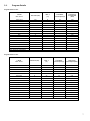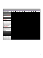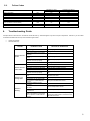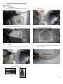
1
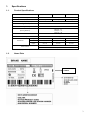
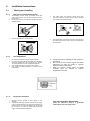
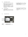
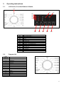
F2 PYTHON SERVICE MANUAL 1 TABLE OF CONTENTS 1. Specifications 1.1. Product Specifications 1.2. Name Plate 2. Installation Instructions 2.1. Moving and Installing 2.2. Detergent Box Group 3. Operating Instructions 5.1. LCD Screen, Function Buttons & Knobs 5.2. Program List 5.3. Program Details 5.5. Child Lock 4. Test Mode 6.1. Autotest 5. Service Mode 5.1. Service Autotest 5.2. Failure Codes 6. Troubleshooting Guide 7. Disassembly and Assembly Instructions 7.1. Top Plate 7.2. Door 7.3. Tub Bellows Seal 7.4. Detergent Drawer 7.5. Control Panel 7.6. Front Panel 7.7. Detergent Drawer Housing 7.8. Power Cable Group and Parazit Filter 7.9. Electronic Pressure Switch (EPS) 7.10. Door Lock 7.11. Pump Motor 7.12. Front Counterweight 7.13. Heater 7.14. Tub Bellows Seal 7.15. Transport Screw 7.16. Upper Counterweight 7.17. Washing Group 7.18. Shock Absorber PIN 7.19. Belt 7.20. Driven Pulley 7.21. Motor 7.22. Tub Entrance with Bellow Hose 7.23. Pressure Switch Hose Group 7.24. Tub 7.25. Drum 8. Component Specifications 8.1. Drain Pump 8.3. Resistance 8.4. NTC 8.5. Valve 8.6. Electronic Pressure Switch (EPS) 8.7. Motor 8.8. Door Lock 9. Wiring Diagram 9.1. Wiring Diagram NA-127VB3 and NA-147VB3 PAGE 3 3 3 4 4 5 6 6 6 7 8 9 9 11 11 12 12 14 14 14 16 16 16 18 19 20 21 21 21 22 22 23 23 24 24 25 25 25 25 26 26 26 26 27 27 28 29 30 31 32 34 35 35 2 1. 1.1. Specifications Product Specifications 50 lt 55 lt Product Type Front Loader Capacity 7 kg 8 kg Max Spin Speed (r/min) 1200 Energy Efficiency A++ Washing Efficiency A Spinning Efficiency 600 rpm → E 800 rpm → D 1000 rpm → C 1200 rpm → B Control Panel LED display Wash Programs 15 settings Dimensions 61 lt 9 kg Height 84,5 cm 84,5 cm 84,5 cm Width 59,7 cm 59,7 cm 59,7 cm Depth 52,7 cm 55,2 cm 58,2 cm Child Lock Other Features Delay Time 1.2. Name Plate 0000 SERVICE INDEX NUMBER 3 2. Installation Instructions 2.1. 2.1.1. 1. 2. 3. 2.1.2. 1. 2. 3. 4. 2.1.3. 1. 2. Moving and Installing Removal of Transportation Screw Transportation screws, which are located at the back side of the machine, must be removed before running the machine. Loosen the screws by turning them anticlockwise with a suitable spanner. Pull out the screws and rubber washers. 4. The holes where the transport screws have been removed should be covered with the plastic transport caps found in the accessories bag. 5. The transportation screws that have been removed from the machine must be re-used in any future transporting of the machine. 5. Change the level by adjusting the feet upwards or downwards. After level has been reached, tighten the plastic adjustment nut again by rotating it upwards against the base of the cabinet. Never put cartons, wooden blocks or similar materials under the machine to balance irregularities of the floor. Foot Adjustment Do not install machine on rugs or similar surfaces. For machine to work silently and without any vibration, it should be installed on a flat, non-slippery firm surface. Any suspended floor must be suitably strengthened. You can adjust the level of machine using its feet. First, loosen the plastic adjustment nut away from the cabinet base. 6. 7. Electrical Connection Washing machine requires a 50Hz supply of 220240Volts. A special earthed plug has been attached to the supply cord of washing machine. This plug must be fitted to an earthed socket. The fuse value fitted to this plug should be 13 amps. If you have any doubts about electrical supply, consult a qualified electrician. THIS APPLIANCE MUST BE EARTHED. Insert the machine’s plug to a grounded socket which you can easily reach. 2.1.4. 1. 2. 3. 4. Water Supply Connection Washing machine is supplied with a single (cold) water inlet. To prevent leakage from the connection joints, a rubber washer is included in the hose packing. Fit this washer at the end of water inlet hose on the tap side. Connect the hose to the water inlet valve. Tighten the plastic connector by hand. Please call a qualified plumber if you are unsure about this. Water pressure of 0,1-1 MPa from tap will enable machine to work more efficiently.(0,1 MPa pressure means water flow of more than 8 litres in 1 minute from a fully opened tap) 5. 6. 7. 3. 2.1.5. 1. 2. Drain Connection Make sure that water inlet hoses are not folded, twisted, crushed or stretched. The drain hose should be mounted at a minimum height of 60 cm, and a maximum height of 100 cm from the floor. 2.2. 4. After connection is complete, check for leakage by turning on tap completely. Make sure that water inlet hoses can not become folded, damaged, stretched or crushed when the washing machine is in its final position. Mount the water inlet hose to a ¾” threaded water tap. The end of the drain hose can be connected directly to a drainage stand-pipe or alternatively to a specific connection point designed for that purpose on the waste outlet of a sink unit. Do not extend the drain hose or guarantee will be invalidated. Detergent Box Group VALVE1 MAIN SOFTENER PREWASH VALVE2 PREWASH MAIN SOFTENER = WATER ENTRY VALVE 1 = WATER ENTRY VALVE 2 = WATER ENTRY VALVE 1 + VALVE 2 5 3. Operating Instructions 3.1. LCD Screen, Function Buttons & Knobs PR LD6 LD1 LD2 LD3 LD4 LD7 LD8 LD9 LD10 SW5 PR SW1 SW2 SW3 SW4 SW5 LD1 LD2 LD3 LD4 LD5 LD6 LD7 LD8 LD9 LD10 LD11 3.2. KNOB POSITION 1 2 3 4 5 6 7 8 9 10 11 12 13 14 15 16 LD5 SW4 SW3 SW2 SW1 Program selector 16 programs with ON/OFF. Switch 1, Start / Pause Switch 2 Switch 3 Switch 4 Switch 5 Start/ Pause Led Temperature Function Button Led Delay Time Function Button Led Extra Rinse Function Button Led Spin Phase Led Rinse Phase Led Wash Phase Led Child Lock Activation Led Door Lock Led Lack Of Water Indication Led Pump Failure Indication Led Program List PROGRAM Cotton 90°C Cotton Prewash Cotton Eco Cotton 40°C Eco 20°C Easy Care Wool Rinse Spin Delicate / Hand Wash Sports Wear Mix 30 Blouses/ Shirts Daily 60' Rapid 15' STOP 6 3.3. Program Details Program Details for 50 lt F ALVA 50 lt w/o TJ Total Time (min) Max. T (°C) Total Water Consumption (lt) Total Energy Consumption (kwH) Cotton 90°C 200 81 85 2,36 Cotton Prewash 165 57 100 1,70 Cotton Eco 205 57 50 1,06 Cotton 40°C 195 40 56 1,02 Eco 20°C 98 20 46 0,20 Easy Care 91 45 45 0,55 Wool 55 25 50 0,15 Rinse 42 - 48 0,10 Spin 17 - - 0,06 Hand Wash / Delicate 100 32 75 0,35 Sports Wear 79 30 47 0,32 Mix 85 30 46 0,30 Blouses / Shirts 110 55 49 0,98 Daily 60' 60 60 35 0,90 Rapid 15' 15 30 30 0,10 Off WIT: Water Inlet Temperature Program Details for 55 lt F ALVA 55 lt w/o TJ Total Time (min) Max. T (°C) Total Water Consumption (lt) Total Energy Consumption (kwH) Cotton 90°C 207 81 85 2,36 Cotton Prewash 165 57 100 1,60 Cotton Eco 200 57 52 1,22 Cotton 40°C 190 40 58 1,02 Eco 20°C 98 20 44 0,22 Easy Care 91 45 50 0,56 Wool 55 25 55 0,15 Rinse 42 - 50 0,10 Spin 17 - - 0,06 Hand Wash / Delicate 90 32 76 0,33 Sports Wear 79 30 49 0,30 Mix 85 30 45 0,27 Blouses / Shirts 110 55 49 1,00 Daily 60' 60 60 37 0,85 Rapid 15' 15 30 26 0,13 Off WIT: Water Inlet Temperature 7 Program Details for 61 lt F ALVA 61 lt w/o TJ Total Time (min) Max. T (°C) Total Water Consumption (lt) Total Energy Consumption (kwH) Cotton 90°C 208 81 87 2,40 Cotton Prewash 165 57 102 1,72 Cotton Eco 210 57 66 1,37 Cotton 40°C 190 40 60 1,02 Eco 20°C 98 20 47 0,20 Easy Care 91 45 50 0,57 Wool 55 25 51 0,15 Rinse 47 - 50 0,12 Spin 17 - - 0,06 Hand Wash / Delicate 92 32 73 0,36 Sports Wear 79 30 49 0,35 Mix 85 30 45 0,25 Blouses / Shirts 110 55 49 0,97 Daily 60' 60 60 38 0,92 Rapid 15' 15 30 32 0,11 Off WIT: Water Inlet Temperature * : Programme duration ,Energy and Water Consumption are given for the cycles for programmes are started in set temperature. WIT : Water Inlet Temperature - : Programmes do not take water Temperature may vary depending on the heating time Durations may vary according to wash load (weight and type), tap water and ambient temperature and selected extra functions. 8 3.5. Child Lock Activation 1. Press the SW2 and SW3 buttons simultaneously for 3 sec. 2. L4 and L5 will make fast blink for 2 sec to indicate child lock is activated. Deactivation 1. Press the SW2 and SW3 buttons simulaneously for 3 sec. Child lock during the programme 1. Machine does not respond to any pressing of buttons or changing position of program knob.When the user try to change programme knob during child lock, for F2A, F2B and F2C panels , Led 4 and L5 will make fast blink for 2 sec . 2. L4 and L5 wil make fast blink for 2 sec to indicate child lock is activated. In end condition 1. When cycle is finished child lock is automatically deactivated. In Error Mode 1. Child lock will be automatically deactivated when error is detected. 9 4. Test Mode 4.1. Autotest * This test is for quick checking of the product. You can not see the failure codes. 1. Press SW5 button and simultaneously position program knob to 1 2. After 3 sec, door will be locked and the auto test starts. The test steps are as below; Step1: The pump is activated for 3 seconds and there is EPS check , the frequency value should be between the 46.04 Hz and 43.40 Hz. It checks the EPS and if it is OK it continues the autotest; if it is NOK then it should give E10 ERROR & cancels the autotest ( goes to the selection mode ). Also if any frequency can not be detected, then it means there is problem with connection or EPS, so it gives E10 which is EPS error and cancels the autotest. Step2: The motor ramps to max spin for 15 seconds. While its speed rising up to the maximum speed the EV1 (prewash valve) is activated for 5 seconds and then the EV2 (wash valve) is activated for 5 seconds. Step6: Step3: The motor reduces speed to stop (depends on the motor stop time) for 5 seconds. While it is slowing down it activates EV1 and EV2 valve, concurrently. Step4: The motor turns to right. Step5: The motor turns to left for 5 seconds. Test is stopped. In that period, the option 1 led makes fast blink. The option 1 button is pushed Step7: The EV1 and EV2 are activated concurrently until it reaches pressure sensor's first level frequency ( Hz ) for 5 seconds. Step8: Software will detect NTC's resistance value and will check if the temperature is between 5°C < Tdetected < 40°C . If it is inside the range, heating step will be done. If temperature value is outside the range, then it means NTC is detecting the temperature in a wrong way and heating step will be skipped. For F1A, F1B, F2A,F2B and F2C ''End'' led will be fix on. 10 AUTOTEST 5 Time in seconds (to be adjusted) Entering autotest Changing pow er to 220 50Hz Main Voltage 50 Hz Door Lock Pow ered (Depends on door lock) Motor Ramp to max spin (max. is 15 sec.) Time until motor is stopped (Depends on the motor stop time) Motor Preferred Run (Direction to Right) Motor Inverse Run (Direction to Left) EV1 (flow rate dependent of w asher) EV2 (flow rate dependent of w asher) Test stopped until Prew ash button is pressed (symbol blinking) EV1 + EV2 valves up to first level frequency (Depends on the w ater level) (If machine is a hot w ater one, take w ater from Hot Valve) NTC check Heather resistance Pump EPS measurement Wash Led (LD1) (For F1 and F2) Rinse Led (LD2) (For F1 and F2) Spin Led (LD3) (For F1 and F2) End Led (LD4) (For F1 and F2) 10 15 20 25 30 35 40 45 50 55 60 65 11 5. Service Mode 5.1. Service Autotest End users can only see E1-E2-E3-E4. During service autotest, other failures can be seen. 1. To activate service autotest, Press SW4 button and simultaneously position program knob to 1. 2. After 3 sec, door will be locked , after door is locked, all leds will be fix OFF and machine will get into service autotest mode. Comments : Selector Position 1 Selector Position 2 Selector Position 3 Result Result Result HEATER ON PUMP ON TEST PROGRAM ON When entering in service test, door will be locked. Test is over Door will be unlocked, machine will go to ENS state. The test steps are as below ; Step 1 : Step 3 : Selector Position 1 will be “HEATER ON” Selector Position 3 will be 15 minutes test program. Before heating it should take water till first level frequency then start heating. So machine will make exactly the same algorithm of 15 minutes test program. Heater will be on max. 8 minutes. If temperature doesn’t increase 2 ◦ C in 8 minutes, machine will give NTC failure. (E05). At the end of 15 minutes test program “END” is visualized and door is unlocked. During test pressing other buttons makes no change. Or if the NTC connection is broken then it should give again E05 NTC failure. LD1 Start / Pause button Led → ON LD6 Wash Phase Led → Off LD7 Rinse Phase Led → Off LD8 Spin Phase Led → Off LD9 Door Lock Led → When the door is unlocked it will be off LD2, LD3, LD4 → Off Display → “END” At the end of heating, “SAU” visualization should make slow blink to indicate that the step is over. Note : If user changes the selector position, machine will do what is defined for the new selected position. Step 2 : Selector Position 2 will be “PUMP ON” Temperature will be measured, if it is higher than 50 ° C, it should take 60 sec. cooling water, and then make “Drain + 5 sec.” At the end of pump activation, “SAU” visualization should make slow blink to indicate that the step is over. 12 5.2. Failure Codes Error Indication Door is not locked Door is unlocked during programme Lack of water Pump failure Overflow NTC or Heater Failure Motor Failure - 1 (Tachometer open-short circuit or motor connector is disconnected) Motor Failure - 2 (triac short circuit) Electronic Pressure Sensor 6. E01 E01 E02 E03 E04 E05 Indication For User Yes/No Yes Yes Yes Yes Yes No Indication For Service Yes/No Yes Yes Yes Yes Yes Yes E06 No Yes E08 E10 No No Yes Yes Error Number Troubleshooting Guide All repairs which must be done on the machine should be done by authorized agents only. When a repair is required for machine or you are unable to eliminate the failure with the help of the information given below: Unplug the machine. Close the water tap. FAILURE Machine does not operate. Machine does not receive water. Machine is not draining water. Machine is vibrating. PROBABLE CAUSE METHODS OF ELIMINATION It is unplugged. Fuse is defective. Insert the plug into the socket. Change fuse. Start / Pause button has not been pressed. Press the start / pause button. The program knob is in 0 (off) status. Bring the program knob on the desired status. The door is not shut properly. Shut the door properly. You should hear the click. Child lock is active. Water tap is closed. The water inlet hose may be bent. The water inlet hose is obstructed. The water inlet filter is obstructed. See page 9. Open water tap. Check the water inlet hose. Clean the filters of water inlet hose. Clean the valve inlet filters. The door is not shut properly. Shut the door properly. You should hear the click. The drain hose is obstructed or bent. The pump filter is obstructed. The clothes are not placed inside the machine in a well-balanced manner. The feet of machine are not adjusted. Transportation screws are not removed. There is a small amount of clothes in the device. Excessive amount of clothes are filled in the machine or the clothes are not placed in a well-balanced manner. Check the drain hose. Clean the pump filter. Spread the clothes inside the machine in an orderly and well-balanced manner. Adjust the feet. Remove transportation screws. It does not prevent operation of the machine. Do not exceed the recommended quantity of clothes and spared clothes in the machine in a well-balanced manner. 13 FAILURE Excessive foam in the detergent drawer PROBABLE CAUSE Too much detergent has been used. Wrong detergent has been used. The washing result is bad. The washing result is not good. Laundry too dirty for the program you have selected. The amount of detergent used is not sufficient. Clothes exceeding the maximum capacity has been filled in machine. Water may be hard. Distribution of the clothes in machine is not well-balanced. The water is seen in the drum during washing. There are residues of detergent on the clothes. There are grey stains on the clothes. METHODS OF ELIMINATION Press the start/pause button. In order to stop the foam, dilute one table-spoon of softener in half liter of water and pour it in the detergent drawer. Press the start/pause button after 5-10 minutes. Arrange the amount of the detergent properly in the next washing process. Use only the detergents produced for full automatic machines. Select a suitable program. Use more detergent according to the detergent. Put the clothes in machine in a manner not to exceed its maximum capacity. Use the amount of detergent according to the declaration of the detergent producer. Spread the clothes inside the machine in an orderly and well-balanced manner. No failure. The water is at the lower part of the drum. The pieces of some detergents which do not dissolve in water may stick to clothes as white stains. These stains may be caused by oil, cream or ointment. The spinning No failure. The unbalanced load process is not done control works in that way. or starts with delay. By calibrating machine for “Rinsing” program, make an additional rinsing or eliminate the stains After drying with the help of a brush. In the next washing operation, use the maximum detergent amount declared by the detergent producer. The unbalanced load control system will try to distribute clothes in a homogenous manner. After clothes are distributed, passage to spinning process will be realized. In the next washing process, place clothes into the machine in a well-balanced manner. 14 7. Disassembly and Assembly Instructions 7.1. Top Plate 1. Remove two screws that fix the top-plate at the back. 2. Push the top-plate back and pull it up. 7.2. 1. 2. Pull the door up. 3. Remove screws that fix the door group. 4. Put the door outside plastic with helping screwdriver as it is shown in the picture. Door Remove two screws that fix the door. (by using the T25) T25 15 5. Remove the door inside plastic as it is shown in the picture. 6. Remove six screws that fix the door hinge as it is shown in the picture. 7. Remove the door handle as it is shown in the picture. 8. Remove the door handle pim as it is shown in the picture. 16 7.3. 1. Tub Bellows Seal First remove the spring wire fixing the tub bellows seal by using the small size screw driver. Pull the tub bellows seal as it is shown in the picture. 7.5. 2. 7.4. 1. Control Panel 1. Remove the screw which fix the control panel to the front panel. 2. Remove three screws fixing the control panel. Remove the tub bellows seal-body fixing spring. Detergent Drawer Remove the detergent drawer and pull it up carefully 17 3. Pull the control panel up. 4. Press the button as shown in the picture. 7. Remove electronic card as it is shown in the picture. 5. Remove the cable group as it is shown in the picture. 8. Push clips to remove to selection button as it is shown in the Picture. 6. Remove electronic card cover as it is shown in the picture by using small screw driver. 9. Remove selection button as it is shown in the Picture. 18 7.6. 1. 2. Front Panel Remove the pomp cover as it is shown in the picture. Remove two screws fixing bottom the front panel. 3. Remove two screws fixing upper the front panel. 4. Remove two screws fixing door lock it is shown in the picture. 5. Remove two screws fixing the body group at the front as it is shown in the picture. 19 6. Lift upper support braket up slightly it it ishown in the picture. 7. Remove the pump cover housing as it is shown in the picture. 7.7. 1. 8. Remove the front panel as it is shown in the picture. Detergent Drawer Housing Remove detergent drawer group two clips fixing the upper support bracket as it is shown in the picture. 20 1. Remove the tub seal clamp by using the pliers, which is attached to the detergent drawer housing. 2. Remove the four connectors that is connected to the feed valve as it is shown in the picture. 5. 7.8. Filter 3. Turn the feed valve counter clockwise slightly to remove. 4. Remove the detergent drawer screw. Remove the detergent drawer housing assembly. Power Cable Group and Parazit 1. Remove the five conectors that is connected to the parasite filter. 2. Remove two screws fixing the parasite filter. 21 3. Pull the power cable group up as it is shown in the picture. 4. Remove parasite fitler fixing body group as it is shown in the picture. 3. 7.10. 1. 7.9. 1. 2. Remove the eps hose handcuffs and eps hose as it is shown in the picture. Door Lock Remove the connector that is connected to the door lock. Electronic Pressure Switch (EPS) Remove the connector that is connected to the EPS. Pull the EPS upward to remove as it is shown in the picture. 7.11. Pump Motor 1. Remove pipe clip that fixes the drain hose. 2. Remove pipe clip fixing the tub outlet hose. 22 3. 4. 7.12. Remove the connector that is connected to the pump motor. 7.13. Heater 1. Remove the four connectors that is connected to the heater. 2. Remove one nut fixing the heater slightly (box wrench size 8 mm) Remove four screws fixing the pump motor. Front Counterweight 1. Remove four screws fixing the front counterweight on the front. (Box wrench size 13 mm) 2. Pull the counterweight back 23 3. 7.14. Hold the heater and pull it out. 7.15. Transport Screw 1. Remove four transport screws (box wrench size 10 mm) 2. Hold the transport screw and pull it out. Tub Bellows Seal 1. Remove the tub gasket clip by using small screwdriver. 2. Hold the tub bellows seal and gasket-body fixing spring together, and pull them up. 24 7.16. Upper Counterweight 2. 1. 2. 7.17. 1. Remove two screws fixing the upper counterweight by using box wrench size 13 mm. Cut the five lead wire holders as shown the pictures. a) b) c) d) 3. Remove the four screws fixing the spring hanger sheet iron. 4. Remove the washing group as it is shown in the picture. Remove the upper counterweight Washing Group Remove the connector that is connected to the motor. 25 7.18. 1. 7.19. 1. 7.20. 1. Shock Absorber PIN Remove two pins fixing the shock absorber as shown in the picture. Belt Remove the belt as it is shown the picture. 2. 7.21. Remove the driven pulley it is shown the picture. Motor 1. Remove the four screws fastening the motor under the tub by using T40 2. Pull the motor up for disassembly. Driven Pulley Remove the screw fixing driven pulley it is shown the picture (By using T40). 26 7.22. Tub Entrance with Bellow Hose 7.24. 1. 1. 7.23. 1. Remove the tub entrerance with bellow hose. Remove twenty four screws fixing tub using box wrench size 8 mm. Pressure Switch Hose Group Remove screw fixing the pressure switch water reservoir. 7.25. 1. 2. Tub Drum Remove the drum. Remove the tub exit with bellow hose with ball by using box wrench size 10 mm. 27 8. 8.1. Component Specifications Drain Pump Drain pump is both a mechanical and elektrical component which is used to drain water inside the washing machine. It has an synchronous motor inside. For better performance maintanance, pump filter should be cleaned regularly. 8.1.1. Technical Features Nominal voltage Nominal current Nominal power Frequency Resistor (coil) Water flow: Thermal protector 8.1.2. 220 - 240 V 0.28 A (±10 %) 37 W 50 Hz 130 Ω (±5%) 17 L/min(to 1 m height) YES Checking of Component Check the resistance value on the component with multimeter as shown in belows figures. Resistance value should be between 125- 140 Ω Checking the component 28 8.2. Resistance Heating element (Resistance) is a component which is desingned to regulate temperature of water inside the drum. It has three connections: Phase, notral and ground connections. 8.2.1. Technical Features Kind of heating Nominal voltage Nominal power Resistance Thermal fuse 8.2.2. Tubular heating element with NTC – sensor 230 V 2000 W (±5%) 24,8 ±5% Ω (for NA-127VB3 and NA-147VB3) 2 – sided Checking of Component Check the resistance value on the component with multimeter as shown in below pictures. Checking the component 29 8.3. NTC Component which sends signals to PCB about the water temperature inside the tub. The Resistance (Ohm) value of the NTC decreases as the temperature increases. 8.3.1. Technical Features Tem (°C) -10 -5 0 5 10 15 20 25 30 35 40 45 50 55 60 65 70 75 80 85 90 95 100 R min (kΩ) 54,9 43,0 33,9 27,0 21,6 17,4 14,1 11,5 9,4 7,8 6,4 5,4 4,5 3,8 3,2 2,7 2,3 1,9 1,7 1,4 1,2 1,1 0,9 R max (kΩ) 62,6 48,6 38,1 30,1 23,9 19,1 15,4 12,5 10,2 8,3 6,9 5,7 4,7 3,9 3,3 2,8 2,4 2,0 1,8 1,5 1,3 1,1 1,0 NTC Tempure – Resistance Values 8.3.2. Checking of Component Check the resistance value on the component with multimeter as shown in below pictures. Checking the component 30 8.4. Valve Valve is an electrical and mechanical component which is designed to take water from the network system into the washine machine. It is operated by PCB card. 8.4.1. Technical Features Nominal voltage Nominal power Frequency Rated flow: Operating water pressure 8.4.2. 220 – 240 V 8 VA 50-60 Hz 7 lt/min (±15 %) 0.0,3 – 1 Mpa Checking of Component Check the resistance value on the component with multimeter as shown in below pictures. Valve water flow rate should be between 6 lt/min - 8 lt/min. Each valve bobbin resistance values should be between 3,3 - 4.2 kohm . Checking the component 31 8.5. 8.5.1. Electronic Pressure Switch (EPS) Technical Features Electromagnetic field occurs as a result of the vibration of the membrane which is under pressure in the coil. The nucleus part is moved up and down by the electromagnetic field. The water level is regulated by the frequency which is controlled by the PCB and changes according to the movement of the nucleus part. 8.5.2. Checking of Component 1. Push the door lock slider with screwdriver. 6. Cut off the energy input when the water intake finishes and drum begins to rotate. 5. Select the 1st program and start the machine. 7. Check the water level inside the drum with ruler. It should be 10 cm ±1. 32 8.6. Motor The washing machine has an asynchronous motor. It is controlled by the PCB. It is essential to check the motor for correct diagnosis and quick servicing. In the below picture, socket points on the motor is shown to measure with multimeter. Tacho Socket Terminal Stator Full Field Coil Socket Terminal Stator Half Field Coil Socket Terminal Motor Socket Terminals 33 Tacho and stator (full field-half field) ohm resistance values for the motor types are listed in the below table. MOTOR KODU FİRMA STATOR (TAM SARGI) (ohm) TAKO (ohm) STATOR (YARIM SARGI) (ohm) SICAKLIK 32003986 ACC 3.30-/+ 7% 184-/+7% 1.20-/+7% 20 °C 32004905 ACC 2.70-/+ 7% 184-/+7% 1.04-/+7% 20 °C 32006966 ACC 3.00-/+ 7% 184-/+7% 1.50-/+7% 20 °C 32007450 ACC 2.70-/+ 7% 184-/+7% 1.08-/+7% 20 °C 32004572 ACC 1.20-/+ 7% 184-/+7% 0.60-/+7% 20 °C 32008809 ACC 0.96-/+ 7% 184-/+7% - 20 °C 30027193 ANAIMEP 1.87-/+7% 180-/+10% - 20 °C 30023397 ANAIMEP 1.75-/+7% 180-/+10% - 20 °C 32002064 ANAIMEP 2.01-/+7% 180-/+7% - 20 °C 32003425 ANAIMEP 2.01-/+7% 180-/+7% - 20 °C 32000536 ASKOLL (CESET) 1.01-/+7% 68.7-/+7% - 20 °C 32000271 ASKOLL (CESET) 1.40-/+7% 68.7-/+7% 0.56-/+7% 20 °C 32000535 ASKOLL (CESET) 1.24-/+7% 68.7-/+7% - 20 °C 30027193 ASKOLL (CESET) 2.26-/+7% 68.7-/+7% - 20 °C 32008661 ASKOLL (CESET) 1.90-/+7% 68.7-/+7% 0.74-/+7% 20 °C 30023397 ASKOLL (CESET) 1.83-/+7% 68.7-/+7% - 20 °C 32004970 ATB 1.62-/+ 7% 87-/+12% - 20 °C 32004969 ATB 1.62-/+ 7% 87-/+12% 0.81-/+7% 20 °C 32009041 ATB 1.62-/+ 7% 87-/+12% 0.81-/+7% 20 °C 32004968 ATB 1.20-/+ 7% 87-/+12% - 20 °C 32009040 ATB 1.20-/+ 7% 87-/+12% - 20 °C 32008659 BROAD OCEAN 2.15-/+7% 66.7-/+7% - 20 °C 32008660 BROAD OCEAN 2.15-/+7% 66.7-/+7% - 20 °C 32005496 IDEA 4.60-/+7% 227-/+7% - 20 °C 32007954 WELLING 2.08-/+7% 66.6-/+7% - 20 °C 32007955 WELLING 1.59-/+7% 66.6-/+7% - 20 °C 32008852 WELLING 2.00-/+7% 66.6-/+7% - 20 °C 32008853 WELLING 2.15-/+7% 66.6-/+7% - 20 °C Resistance values for the motor types 34 8.7. Door Lock Door lock is activated at the beginning of the program in order to prevent the door from opening. It can be unlocked approximately after 2 minutes of the program end. This time delay is caused by the PTC which is assambled in the door lock. 8.7.1. Technical Features Lock Time (20 °C) Unlock Time (20 °C) Nominal voltage Nominal current 8.7.2. 2” – 6” 35” – 75” 220 V 16 (4) A Checking of Component Check the resistance value on the component with multi-meter as shown in below figures. Resistance value on the PTC should be 1000 Ω ±50% at 25 °C. That resistance value can be measured from terminal 3-4 (See wiring diagram page 51 below). 2 3 4 5 35 9. 9.1. Wiring Diagram Wiring Diagram