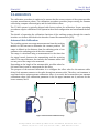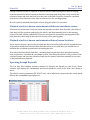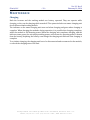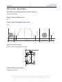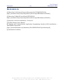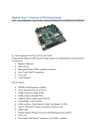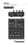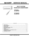
1
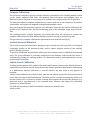
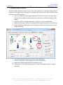
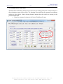
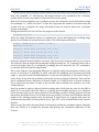
Positioned for the Future ANS-410 Autonomous Navigation System Operators Manual Version 2.1 Rev 3 2014-02-10 HEADQUARTERS: 2200 NORTH SQUIRREL ROAD • ROCHESTER, MICHIGAN 48309 • USA PHONE: (248) 648-4777 • FAX: (248) 648-4799 • HTTP://WWW.ITRACK-LLC.COM Ver. 2.1 Rev 3 iTrack, LLC –2– February 10, 2014 HEADQUARTERS: 2200 NORTH SQUIRREL ROAD • ROCHESTER, MICHIGAN 48309 • USA PHONE: (248) 648-4777 • FAX: (248) 648-4799 • HTTP://WWW.ITRACK-LLC.COM Ver. 2.1 Rev 3 iTrack, LLC –3– February 10, 2014 I NTRODUCTION This document contains the operating procedures for the TS-400 UWB tracking system. Operating procedures include setup, configuration, system calibration, tracking operation and sanitization. T ERMINOLOGY Coordinate system configuration represents the setup and configuration of the positioning system immediately relative to the beacons. Reference Frame represents the user-configured positioning relative to an object of interest. The user configures the reference frame with commands RO and RA. Plane of Operation.is the horizontal in which the tracking module is being moved, and in which the X and Y position coordinates are being calculated. The height of the plane is manually or automatically adjusted. A Beacon represents a stationary reference point in the operating space. The beacon module contains the hardware to support the tracking system. A Target module is the device in the system that is to be tracked. All operations originate from and are coordinated by the tracking module. The tracking module may consist of an Inertial module, and an RF module. The RF module includes the radio hardware and battery, and its location is not critical to tracking. Inertial tracking represents the position increments caused by a short horizontal move on the surface of the tracking object. The accelerometers are used to acquire a position offset that is augmented to the tracking information. Inertial tracking is optional. Copyright All rights reserved. © 2012, iTrack, LLC HEADQUARTERS: 2200 NORTH SQUIRREL ROAD • ROCHESTER, MICHIGAN 48309 • USA PHONE: (248) 648-4777 • FAX: (248) 648-4799 • HTTP://WWW.ITRACK-LLC.COM Ver. 2.1 Rev 3 iTrack, LLC –4– February 10, 2014 HEADQUARTERS: 2200 NORTH SQUIRREL ROAD • ROCHESTER, MICHIGAN 48309 • USA PHONE: (248) 648-4777 • FAX: (248) 648-4799 • HTTP://WWW.ITRACK-LLC.COM Ver. 2.1 Rev 3 iTrack, LLC –5– February 10, 2014 T ABLE OF C ONTENTS INTRODUCTION .............................................................................................................................................. 3 TERMINOLOGY ................................................................................................................................................ 3 Copyright ............................................................................................................................................................................................... 3 TABLE OF CONTENTS .................................................................................................................................... 5 INSTALLATION AND SETUP ......................................................................................................................... 7 In Case 1 ................................................................................................................................................................................................. 7 System installation and setup ........................................................................................................................................................ 7 System Operation and Configuration .......................................................................................................................................... 8 CALIBRATION .................................................................................................................................................. 9 Antenna Cable Calibration .............................................................................................................................................................. 9 Antenna Offset Calibration ........................................................................................................................................................... 12 Compass Calibration ....................................................................................................................................................................... 13 Inertial Sensors Calibration ......................................................................................................................................................... 13 Vehicle Travel Calibration ............................................................................................................................................................. 13 SYSTEM CALIBRATION SCENARIO ......................................................................................................... 15 SYSTEM INSTALLATION ............................................................................................................................. 19 Setup Beacons .................................................................................................................................................................................... 19 Configure coordinate system ....................................................................................................................................................... 19 Beacon placement and assignment ........................................................................................................................................... 19 Setup Coordinate System ............................................................................................................................................................... 19 Assigning the reference coordinate frame and calibrating orientation ...................................................................... 21 Considerations for performance ................................................................................................................................................ 21 Assigning the reference coordinate frame and calibrating orientation ...................................................................... 21 Registering local coordinates ...................................................................................................................................................... 22 Considerations for accuracy ......................................................................................................................................................... 22 Data Logging ....................................................................................................................................................................................... 23 PARAMETER TUNING ................................................................................................................................. 25 Tracking parameters ....................................................................................................................................................................... 25 HEADQUARTERS: 2200 NORTH SQUIRREL ROAD • ROCHESTER, MICHIGAN 48309 • USA PHONE: (248) 648-4777 • FAX: (248) 648-4799 • HTTP://WWW.ITRACK-LLC.COM Ver. 2.1 Rev 3 iTrack, LLC –6– February 10, 2014 Vehicle control parameters .......................................................................................................................................................... 25 SYSTEM OPERATION .................................................................................................................................. 27 LED indicator definition................................................................................................................................................................. 27 Checking Proper Operating Conditions.................................................................................................................................... 27 Selecting a Task ................................................................................................................................................................................. 27 Record a task in a new environment without beacons ....................................................................................................... 27 Record a task in a new environment with beacons ............................................................................................................. 27 Playback a task in a known environment with known coordinate system ................................................................. 28 Playback a task in a known environment with new beacon locations ......................................................................... 28 Operating through Raynok® ........................................................................................................................................................ 28 Operating through Eterhnet/IP ................................................................................................................................................... 29 Operating through the PcWin interface ................................................................................................................................... 29 Entering a path as an excel file .................................................................................................................................................... 29 TROUBLE SHOOTING ................................................................................................................................. 31 Initialization and Coordinate Setup .......................................................................................................................................... 31 Vehicle Operation ............................................................................................................................................................................. 31 Tracking ............................................................................................................................................................................................... 31 Autonomous path following ......................................................................................................................................................... 32 MAINTENANCE ............................................................................................................................................. 33 Charging ............................................................................................................................................................................................... 33 TYPICAL APPLICATION SCENARIO ........................................................................................................ 35 OPTIONAL FEATURES ................................................................................................................................ 37 Orientation tracking using secondary Antenna .................................................................................................................... 37 Master-Slave Configuration .......................................................................................................................................................... 37 Time-Lapse Photography operation .......................................................................................................................................... 37 Precision Park Control ................................................................................................................................................................... 37 Vehicle Platform Leveling .............................................................................................................................................................. 37 INDEX .............................................................................................................................................................. 39 REFERENCES ................................................................................................................................................. 41 HEADQUARTERS: 2200 NORTH SQUIRREL ROAD • ROCHESTER, MICHIGAN 48309 • USA PHONE: (248) 648-4777 • FAX: (248) 648-4799 • HTTP://WWW.ITRACK-LLC.COM Ver. 2.1 Rev 3 iTrack, LLC –7– February 10, 2014 I NSTALLATION AND S ETUP The basic version of the TS-400 Tracking system includes 4 beacons and 1 tracking module. The system ships in 3 rugged Pelican cases. In Case 1 6 Beacon modules 1 UWB antenna cable 1 GPS/WLAN antenna cable 7 Broadspec antennas 1 UHF antenna 1 AC4790 USB transceiver 1 ANS-410 vehicle controller 1 CD with software, drivers, manuals 1 User Manual Mounting hardware for Beacons System installation and setup The Beacon Module has two antenna connectors. Connector Net A is used for upper antennas, to be used for tracking on the upper side of the vehicle, while connector Net B is used for the lower antenna, to be used for tracking on the bottom side of the vehicle. Figure 1 Beacon Module The light indicators on the side of the beacon provide feedback for the operating state and health of the module. HEADQUARTERS: 2200 NORTH SQUIRREL ROAD • ROCHESTER, MICHIGAN 48309 • USA PHONE: (248) 648-4777 • FAX: (248) 648-4799 • HTTP://WWW.ITRACK-LLC.COM Ver. 2.1 Rev 3 iTrack, LLC –8– February 10, 2014 The vehicle controller has interface connectors for power and CAN, and antenna connectors for the RF tracking antennas, WIFI, and optionally for GPS and a 900 MHz communication link. Two LED indicators are installed to indicate system operation and status. System Operation and Configuration For the initial configuration and setup, and particularly for calibrating the system properly, the user should connect to the system using the PC software interface. Refer to the User’s manual for the PcWin software for installation and operation of the software. The following Sections describe the calibration. Configuration and operation of the system. HEADQUARTERS: 2200 NORTH SQUIRREL ROAD • ROCHESTER, MICHIGAN 48309 • USA PHONE: (248) 648-4777 • FAX: (248) 648-4799 • HTTP://WWW.ITRACK-LLC.COM Ver. 2.1 Rev 3 iTrack, LLC –9– February 10, 2014 C ALIBRATION The calibration procedure is conducted to ensure that the sensor outputs of the system provide accurate measurement values. The calibration procedure provides proper setting for antenna cable delay, compass offset and gain, and for inertial bias values. The TS-400 system is typically shipped with factory values for calibration. Proper operating procedures require calibration of the system in the actual configuration and environment before use. The details of operating the calibration functions of the tracking system through the console interface are further described in the Interface Control Documentation (ICD). Antenna Cable Calibration The tracking system uses range measurements from the tracking module to the beacons to determine the current position. The range is defined as the distance from the radiating point of one antenna to the radiating point of the other antenna. The range is calculated using a measurement for the time that the signal travels between the transmitting and the receiving radios. This travel distance also includes the antenna cables that are not part of the range to be measured. Depending on the length of the antenna cable, an offset value for the travel time is used to compensate for the delay. The purpose of the antenna calibration is to configure the offset value for the antenna cable delay. Each antenna connects to the radio through an antenna cable. Therefore, each antenna is associated with a unique antenna calibration value. As a result, the beacons have two antenna calibration values. One calibration parameter is for the upper antenna net A, and one for the lower antenna, Net B. D Target Beacon 101 Figure 2 Basic Antenna Calibration Setup HEADQUARTERS: 2200 NORTH SQUIRREL ROAD • ROCHESTER, MICHIGAN 48309 • USA PHONE: (248) 648-4777 • FAX: (248) 648-4799 • HTTP://WWW.ITRACK-LLC.COM Ver. 2.1 Rev 3 iTrack, LLC – 10 – February 10, 2014 The basic setup for calibration is to place beacons and the tracking modules in position, and manually measure the distance between the radiating points of the antenna for the modules to be calibrated with a tape measure. (An appropriate distance for calibration is in the similar range as the planned normal operating range). Then the antenna calibration parameter can be tuned to match the actual measured distance with the reported range from the system. This method can be used when one of the two modules (for example the target module) has already been properly calibrated, but cannot be used when no modules have yet been calibrated. Figure 2 illustrates the basic antenna calibration setup. If D is measured at 15¼ meters distance, then the command to the target module to perform the calibration is CA101,15250 DA Beacon 103 DAB DB Target Beacon 102 Figure 3 Advanced Antenna Calibration Setup The advanced method for calibration is used to calibrate three modules, when none of these three modules have been calibrated yet. The setup for this method of calibration is illustrated in Figure 3. Two beacons and the tracking module are placed in a triangular orientation. The HEADQUARTERS: 2200 NORTH SQUIRREL ROAD • ROCHESTER, MICHIGAN 48309 • USA PHONE: (248) 648-4777 • FAX: (248) 648-4799 • HTTP://WWW.ITRACK-LLC.COM Ver. 2.1 Rev 3 iTrack, LLC – 11 – February 10, 2014 distance between the radiating points of the antennas for the modules to be calibrated (DA, DB, and DAB) are manually measured a tape measure. A command to the host interface of the tracking module can be used to configure the antenna calibration parameters for the beacons and the tracking module from the measured distance. If for example DA was measured at 6.9 m, and DB was measured at 7.2 m and DAB between the beacons was measured at 6.3 m, then the command line for calibration would be as follows, CA102,103,7200,6900,6300 Once calibrated, the tracking module can be used for the basic antenna calibration setup, discussed in the previous paragraph, to calibrate the remaining antennas. When the system is properly calibrated, the values for the beacon bias should be small, when the tracking module is in line-of-sight of the beacons. When values for the beacon bias are more than an inch or two off, then it is advised that antenna calibration be re-checked. The figures below illustrate beacon bias values for a properly calibrated system, and for a poorly calibrated system. 10.62 7.08 Bcn102 Bcn104 Bcn111 Bcn109 3.54 0.00 -3.54 -7.08 -10.62 -14.16 10.62 -17.70 7.08 Figure 4 Beacon Bias values for a properly calibrated system. Bcn102 Bcn104 Bcn109 Bcn111 3.54 0.00 -3.54 -7.08 -10.62 -14.16 Figure 5 Beacon Bias values for a poorly calibrated system. -17.70 HEADQUARTERS: 2200 NORTH SQUIRREL ROAD • ROCHESTER, MICHIGAN 48309 • USA PHONE: (248) 648-4777 • FAX: (248) 648-4799 • HTTP://WWW.ITRACK-LLC.COM Ver. 2.1 Rev 3 iTrack, LLC – 12 – February 10, 2014 Antenna Offset Calibration The TS-400 tracking system is designed to track and report the position of the sensor device that is mounted to the tracking module. Since the RF tracking subsystem reports the location of the antenna in space, and additional offset is required in the proper direction to determine the 3D location of the sensor. The orientation of the tracking module (roll, pitch and yaw) is used to point an offset vector from the antenna to the sensor module. The dimensions of the offset vector must be configured by the user, and may vary, as the antenna may be mounted to the sensor module in different ways. If the antenna offset is 2’ in the x-direction, 5” in the y-direction and 5’ in the vertical z-direction, then the command line for Antenna Offset calibration would be CP6010,127,1524 Alternatively, use the Configuration screen in the Dashboard of the PcWin software to set the coordinates of the antenna offsets. A = (1.25,-0.2,5) X CP1250,-200,500 Y Figure 6 Vehicle reference frame with example antenna offset location If antenna cable length has been calibrated for the vehicle and for the beacons, and if a reference point has been defined within the coordinate system, then an alternative method for finding the antenna location is to place the vehicle in the center of the reference frame (0,0) at 0 deg. orientation, and capture the antenna offset by monitoring the RF tracking position. Antenna height: insert chart with biases when height is wrong. Tips for tuning the antenna offset calibration on the vehicle: Aim the vehicle at one of the beacons. Manually rotate the vehicle counter-clockwise to 180 degrees (facing away from the beacon). The bias should remain small. If the bias shows a positive hump, then back to 0, then increast the Y-offset. If the bias at 180 deg. is positive, then increase the X-offset. HEADQUARTERS: 2200 NORTH SQUIRREL ROAD • ROCHESTER, MICHIGAN 48309 • USA PHONE: (248) 648-4777 • FAX: (248) 648-4799 • HTTP://WWW.ITRACK-LLC.COM Ver. 2.1 Rev 3 iTrack, LLC – 13 – February 10, 2014 Compass Calibration The electronic compass is used to provide absolute orientation for the tracking module, based on the earth’s magnetic field. Since the magnetic field orientation and strength varies on different locations on earth, it is necessary to re-calibrate the compass at the site of operation. The basic procedure for compass calibration is to expose each axis of the compass to all possible orientations, and capture the magnetic strength measurement values. Once the compass has been fully exposed, the calibration values for the bias are defined as the median of the captured data, and the normalizing gain as the maximum range away from the bias. The tracking module contains automatic procedures that allow the operator to conduct the compass calibration in the field without having to monitor, record or measure any data. The procedure for compass calibration is explained in more detail in the ICD [2]. Inertial Sensors Calibration The inertial sensors (accelerometers and gyroscopic sensors) are used to provide roll and pitch orientation relative to the horizontal plane, and to capture physical motion of the tracking module during operation. To produce normalized measurement values, also these sensors must be calibrated for bias and scale. The scale calibration is currently configured in the firmware, whereas the bias value is calibrated by placing the tracking module on a horizontal surface, and capturing the current sensor values as the bias. Vehicle Travel Calibration Tracking and navigation of the vehicles also takes vehicle motion into account. Vehicle motion is captured from the wheel speeds. Omni-directional vehicles provide vehicle motion information in 3 dimensions, whereas skid-steer, or steered vehicles can only drive in two degrees of freedom. Vehicle travel calibration is needed to make sure that the vehicle reports the accurate amount of travel, based on wheel speed information. The basic process consists of starting the vehicle in a known location, tell it to travel to another location, and compare the actual travel distance (e.g. measured with a tape-measure) to the reported travel distance, and adjust the calibration parameter to match the two. The ANS-400 system has a built-in method to calibrate the vehicle travel. Always verify. HEADQUARTERS: 2200 NORTH SQUIRREL ROAD • ROCHESTER, MICHIGAN 48309 • USA PHONE: (248) 648-4777 • FAX: (248) 648-4799 • HTTP://WWW.ITRACK-LLC.COM Ver. 2.1 Rev 3 iTrack, LLC – 14 – February 10, 2014 HEADQUARTERS: 2200 NORTH SQUIRREL ROAD • ROCHESTER, MICHIGAN 48309 • USA PHONE: (248) 648-4777 • FAX: (248) 648-4799 • HTTP://WWW.ITRACK-LLC.COM Ver. 2.1 Rev 3 iTrack, LLC – 15 – February 10, 2014 S YSTEM C ALIBRATION S CENARIO 1. Straight Line Wheel Speed Calibration (NEW WAY) Wheel speed calibration sets the true travel of the vehicle in X and Y directions, measured from wheel speed. RF tracking must be disabled for this procedure. a. Move vehicle using joystick or pendent into the center of a large open area. b. Open the Console window and type the following in the command line: i. Type SM3 to turn off the RF in the iTrack system. Or uncheck the RF checkbox in the Control dashboard of the PcWin software. ii. Type SV0,0,0 to set current vehicle position to 0,0,0. iii. Mark drive wheel position with tape on floor. iv. Type OM160,1200,0,0,30 to drive the vehicle in a straight line for 30 seconds; or manually drive in a straight line. v. Measure in millimeters from previously taped position on the floor to center of drive wheels. vi. To calibrate vehicle wheel speeds, type CV1,X where X is the measurement in mm. c. Do the same for straight line wheel speed in the y-direction 2. Rotational Wheel Speed Calibration Rotational Wheel speed calibration sets the true rotation of the vehicle, measured from wheel speed. RF tracking must be disabled for this procedure. a. Move vehicle using joystick or pendent into the center of a large open area. b. Open the Console window and type the following in the command line: i. Type SM3 to turn off the RF in the iTrack system. Or uncheck the RF checkbox in the Control dashboard of the PcWin software. ii. Type SV0,0,0 to set current vehicle position to 0,0,0. iii. Type OM160,0,0,1500,100 to tell the vehicle to rotate about its center axis in a counter-clockwise (positive) rotation. The value 1500 represents rotational speed, and may be varied, based on the vehicle configuration. iv. Stop the vehicle once it rotates 360 degrees, by entering the command OM0 v. Type the command CV3,360 to calibrate actual rotational value. HEADQUARTERS: 2200 NORTH SQUIRREL ROAD • ROCHESTER, MICHIGAN 48309 • USA PHONE: (248) 648-4777 • FAX: (248) 648-4799 • HTTP://WWW.ITRACK-LLC.COM Ver. 2.1 Rev 3 iTrack, LLC – 16 – February 10, 2014 3. Antenna Length Calibration. Antenna length calibration configures the delay time parameters in the RF tracking radio to compensate for signal travel through the antenna cable between the radio and the actual emission point of the antenna. a. Place one of the beacons at approximately 50 ft from the vehicle, such that there is a clear line of sight between the antenna of the beacon and the antennas of the vehicle. b. Switch the AVC to tracking antenna A by typing PA on the command line. c. Measure the distance between tracking antenna A and the antenna on the Beacon. d. In the Calibration dashboard, enter the distance in mm, the ID of the beacon, and click on Calibrate. e. f. g. h. Check the command line for the result for the calibration. Switch to antenna port B by typing PB on the command line Repeat the calibration procedure for antenna port B Switch back to the default antenna port A to leave the system ready for normal operation. HEADQUARTERS: 2200 NORTH SQUIRREL ROAD • ROCHESTER, MICHIGAN 48309 • USA PHONE: (248) 648-4777 • FAX: (248) 648-4799 • HTTP://WWW.ITRACK-LLC.COM Ver. 2.1 Rev 3 iTrack, LLC – 17 – February 10, 2014 4. Antenna Offset Calibration Antenna offset calibration defines the location of the tracking antennas A and B relative to the orientation center of the vehicle. The drawing below indicates the assumed coordinates relative to the vehicle, where driving forward means that the vehicle is moving in the positive X direction. a. Enter the antenna locations in the Control Dashboard in mm HEADQUARTERS: 2200 NORTH SQUIRREL ROAD • ROCHESTER, MICHIGAN 48309 • USA PHONE: (248) 648-4777 • FAX: (248) 648-4799 • HTTP://WWW.ITRACK-LLC.COM Ver. 2.1 Rev 3 iTrack, LLC – 18 – February 10, 2014 HEADQUARTERS: 2200 NORTH SQUIRREL ROAD • ROCHESTER, MICHIGAN 48309 • USA PHONE: (248) 648-4777 • FAX: (248) 648-4799 • HTTP://WWW.ITRACK-LLC.COM Ver. 2.1 Rev 3 iTrack, LLC – 19 – February 10, 2014 S YSTEM I NSTALLATION In this section we will discuss the initial system calibration procedures, and the regular operation for position tracking. It is assumed that the hardware is assembled, and that the user has successfully configured the user interface with the TM-400 in the previous section. Setup Beacons Once the beacons have been assambled, they must be placed around the operating area. The preferred arrangement is to have the Beacon ID numbers increment around the area of operation in counter-clockwise. When a beacon is switched on, it will initialize and configure the RF interface and be ready for operation. The STDBY indicator on the beacon will blink every three seconds. The indicator for Net A or Net B represents which antenna port is active for tracking. If Net A and Net B are both off, then the beacon has been sanitized, and must be re-calibrated or re-configured. Configure coordinate system When the beacons and tracking module are on, the system has to be setup for tracking operation. Beacon placement and assignment It is important to take the orientation of the coordinate system in consideration during beacon setup. By default, the lowest Beacon ID is assigned as the center of the coordinate system. The next Beacon ID is assigned to indicate the positive X-axis of the new coordinate system. The next Beacon ID will be in the first or second quadrant, or in the positive Y plane. The API provides for commands that will allow the user to assign which beacon represents the center of the coordinate system (Orig) and which beacon represents the X-axis (Axis). If an erroneous setup occurs, the user will observe values of Y-coordinates for beacons and tracking position with the opposite sign. The orientation can be solved by simply swapping the Origin and Axis reference beacons. This can be done by assigning the Beacon ID of the Origin to the Axis, or vice versa. Setup Coordinate System The system is now ready to calibrate the coordinate system. From the console interface, we will first confirm that each of the beacons is operational and configured properly. The user command IN can be used to discover and list the current beacons that are on standby. Discovering Beacons ... Found 4 beacon modules: 100 101 102 103 When a list of beacon IDs is reported, more detailed information can be requested from the beacons by issuing the command ?B. The response to this command may look like Beacon [100]: Ver=2.4.6036 Net=0 Pwr=10 I=8 Ch=0 Bat=8.08V DA=7536 DB=7545 Beacon [101]: Ver=2.4.6036 Net=0 Pwr=10 I=8 Ch=0 Bat=7.28V DA=7425 DB=7466 Beacon [102]: Ver=2.4.6036 Net=0 Pwr=10 I=8 Ch=0 Bat=7.32V DA=7415 DB=7430 HEADQUARTERS: 2200 NORTH SQUIRREL ROAD • ROCHESTER, MICHIGAN 48309 • USA PHONE: (248) 648-4777 • FAX: (248) 648-4799 • HTTP://WWW.ITRACK-LLC.COM Ver. 2.1 Rev 3 iTrack, LLC – 20 – Beacon [103]: Ver=2.4.6036 February 10, 2014 Net=0 Pwr=10 I=8 Ch=0 Bat=7.36V DA=7290 DB=7420 Next, the command IN5 will discover and assign beacons to be included in the coordinate system, where 5 can be any number of iterations for accurate setup. With four beacons assigned to the coordinate system, the calibration can be initiated by issuing the command IN5, where the value 5 in this case represents the number of iterations that the system will use to optimize the range information from the beacons before the coordinate system is calculated. During the iterations, the user will see the progress in the console: Surveying 5,4,3,2,1 When the range information capture is complete, the system will display the resulting range matrix, and calculate the beacon locations from it. The result may look like this: Results: |AB-BA|=0.037 m, |Rm-Rc|=-0.038 m Generated 4 beacons. Beacon[0]: ID=100 Fcn=1 Pos=(0.00, 0.00, 3.50) Beacon[1]: ID=101 Fcn=2 Pos=(13.38, 0.00, 3.50) Beacon[2]: ID=102 Fcn=3 Pos=(0.20, 5.22, 3.50) Beacon[3]: ID=103 Fcn=3 Pos=(11.40, 6.49, 3.50) If the pre-assigned beacon height is incorrect, then the beacon locations will not be accurate. The values for beacon height can be manually configured using the “SZ” command. After each of the beacon height values is re-configured accordingly, the user may issue the “CB” command to re-calculate beacons from the range matrix. The results indicate that maximum difference in opposite range measurements between any beacon A and beacon B (|AB-BA|) is small, and that the maximum error between measured range to any beacon and calculated distance to any beacon (|Rm-Rc|) is also small. If any of these values is big, then the coordinate system has not been properly initialized. This could be due to calibration issues, difference in beacon heights, or it could be due to beacon locations. Try to adjust the placement of some of the beacons and re-initialize the system to see if the results improve. Now the system is ready to capture position tracking data. Verify that the value for the DOP is small. If it is not small, then the vehicle or tracking antenna height may have to be adjusted. Check the bias values in the charts window. If the tracking system is working properly, then all bias values should be close to 0. If all bias values are positive, or if they are all negative, then the height of the tracking antenna must be adjusted. If some biases are negative and some are positive, then the vehicle location must be reset. Type “RV” on the command line in the Console window. After a setup, the vehicle does not know its orientation within the coordinate system. Manually drive the vehicle in a straight line forward, and monitor the orientation calibration in the Console. HEADQUARTERS: 2200 NORTH SQUIRREL ROAD • ROCHESTER, MICHIGAN 48309 • USA PHONE: (248) 648-4777 • FAX: (248) 648-4799 • HTTP://WWW.ITRACK-LLC.COM Ver. 2.1 Rev 3 iTrack, LLC – 21 – February 10, 2014 Assigning the reference coordinate frame and calibrating orientation Assignment of a reference frame is optional. However, if the programmed path will have to be consistent when beacons are setup differently, then a reference frame should be used to attach the coordinate frame to local markers in the operating space. The reference coordinate frame is the baseline reference for determining location of markers on the target vehicle. The reference coordinate frame is relative and fixed to the vehicle, and must be reset each time the beacons are moved, the vehicle is moved, or when the system is reinitialized. Move to a specific reference point on the vehicle that will always be used to mark the center of the coordinate frame. Make sure that the TM-400 is orientated to align with the positive X-axis of the desired reference frame. Then, issue the command to set current location as Origin. Then move to a second specific reference point on the vehicle that will always be used to mark the X-axis of the reference coordinate frame. Make sure that the TM-400 is orientated to align with the negative X-axis of the desired reference frame (i.e. at this second point, aim the TM-400 to the Origin). Then, issue the command to set current location as Axis. Considerations for performance Compass information Line of sight to beacons When the beacons are setup in a planar configuration, then variations in beacon height will not affect the coordinate setup by much. However, if the target modules is being tracked above or below the plane of operation, then Secondary antenna input for orientation Assigning the reference coordinate frame and calibrating orientation The reference coordinate frame is the baseline reference for determining location of markers on the target vehicle. The reference coordinate frame is relative and fixed to the vehicle, and must be reset each time the beacons are moved, the vehicle is moved, or when the system is reinitialized. Move to a specific reference point on the vehicle that will always be used to mark the center of the coordinate frame. Make sure that the TM-400 is orientated to align with the positive X-axis of the desired reference frame. Then, issue the command to set current location as Origin. Then move to a second specific reference point on the vehicle that will always be used to mark the X-axis of the reference coordinate frame. Make sure that the TM-400 is orientated to align with the negative X-axis of the desired reference frame (i.e. at this second point, aim the TM-400 to the Origin). Then, issue the command to set current location as Axis. A reference frame can also be defined as a pre-determined axes in the coordinate system. The coordinates and orientation can be entered via the Console of the PcWin software as ROx,y RAh HEADQUARTERS: 2200 NORTH SQUIRREL ROAD • ROCHESTER, MICHIGAN 48309 • USA PHONE: (248) 648-4777 • FAX: (248) 648-4799 • HTTP://WWW.ITRACK-LLC.COM Ver. 2.1 Rev 3 iTrack, LLC – 22 – February 10, 2014 Registering local coordinates When the reference frame has been setup, the system will immediately report all tracking information relative to the new reference frame. The user may issue ?P, or set DM5 to request positioning information. The positioning information includes a value for the dilution of precision (DOP), which is roughly an indication for tracking error. Based on the DOP, the user may use the reported position with associated error as the current measurement for 3D location. Considerations for accuracy The overall accuracy of the system results from the cascaded accuracy of each of the phases of the tracking system. The diagram in Figure 7 shows how the different phases cascade to the final tracking performance. Setup, Calibration and Deployment Beacon-to-Beacon Measuremtents Coordinate System Range Measurements Tri-lateration Antenna Offset projection Reference Frame Range Measurements Tri-lateration Antenna Offset projection Micro tracking positioning update Figure 7. Accuracy cascading diagram. The initial setup, calibration and deployment refer to how the system is installed or setup in the operating environment. Antenna cable length calibration and inertial sensor calibration should be done properly. During the deployment of the beacons, it is important to ensure that the beacons antennas are at exactly the same height. Beacon height will not significantly affect the configuration of the HEADQUARTERS: 2200 NORTH SQUIRREL ROAD • ROCHESTER, MICHIGAN 48309 • USA PHONE: (248) 648-4777 • FAX: (248) 648-4799 • HTTP://WWW.ITRACK-LLC.COM Ver. 2.1 Rev 3 iTrack, LLC – 23 – February 10, 2014 coordinate system, but will introduce error in the position tracking when the tracking module operates at a significant height difference from the beacons. Inertial sensors and Compass Information from the accelerometers is used to compute the tilt angles (roll and pitch) of the tracking module, and to compute the tilt compensation of the compass data for heading (yaw). The roll pitch and yaw angles are subsequently used to produce the antenna offset within the reference frame, and to project the small positional increments from the Micro Tracking subsystem. Range Measurements The range measurements to beacons are used in combination with the beacon locations to determine the location of the antenna of the tracking module within the beacon coordinate space. Any errors in the range measurements will affect the accuracy of the position estimate. These errors are significantly larger when the straight path between the tracking module antenna and the beacon antenna is obstructed. If there is no obstruction in the path, we call the measurement a “Line of Sight” (LOS) measurement. Based on the shape of the signal from the transmitting radio, the beacon and tracking modules are able to determine if the range measurement is a LOS measurement or not. The signal strength (RSSI) of the measurement can also affect the accuracy. If the RSSI is too small, then it is difficult to detect the signal shape in the noise (low signal-to-noise ratio or SNR) and when it is too big, the signal may saturate in the receiver and distort the shape of the signal. A distortion in the signal introduces error. When the beacons are setup in a planar configuration, then variations in beacon height will not affect the coordinate setup by much. However, if the target module is operating above or below the plane of operation, then small offsets in beacon height introduce error in the estimated position of the tracking module. Data Logging Internal Data Logging capability is available for high update rate, low duration data capturing. Data is stored on the internal FLASH memory and can be downloaded asynchronously using the PC Firmware Upgrade utility. External Data Logging consists of capturing and storing tracking data using the PC Firmware Upgrade utility in real-time. Update rates are not as high, but the logging duration is virtually unlimited. Refer to the PcWin user’s manual for logging data to a log file. HEADQUARTERS: 2200 NORTH SQUIRREL ROAD • ROCHESTER, MICHIGAN 48309 • USA PHONE: (248) 648-4777 • FAX: (248) 648-4799 • HTTP://WWW.ITRACK-LLC.COM Ver. 2.1 Rev 3 iTrack, LLC – 24 – February 10, 2014 HEADQUARTERS: 2200 NORTH SQUIRREL ROAD • ROCHESTER, MICHIGAN 48309 • USA PHONE: (248) 648-4777 • FAX: (248) 648-4799 • HTTP://WWW.ITRACK-LLC.COM Ver. 2.1 Rev 3 iTrack, LLC – 25 – February 10, 2014 P ARAMETER T UNING Even with proper calibration and setup, the system performance depends much on the properly configured values of the tracking and control parameters. These values can vary for different operating environments and vehicle platforms. User interface window Command line parameters (SP) Tracking parameters P-410 parameters The Transmit Gain setting warrants a bit of discussion. When set to zero, the RCM will transmit at the minimum power supported by the RCM. Setting the transmit gain to a value of 63 will set the unit to maximum transmit power. The default setting is 44. This value has been chosen because it is approximately the maximum FCC transmit power for a standard P410. When operating a P400 or a P410 equipped with optional power amps, then a value 0 is approximately equal to the FCC limit. Appendix B documents the relationship between transmit gain setting and transmit power for these three different configurations. This value determines the number of pulses used in each radio symbol or scan point. Larger PII values result in a higher signal-to-noise ratio (SNR) with longer distance operation at the expense of slower ranging and data rates. All RCM nodes must be pre-configured with identical PII values in order to establish communication and ranging. The user configures the “power of 2” of the pulse integration value. For example, a configured value of PII=7 results in the transmitting node sending 128 pulses per symbol and the receiving node expecting 128 pulses per symbol. If the user needs distance more than speed, he or she can reconfigure PIIs of both transmitter and receiver to 8, providing 2x the SNR in each symbol resulting in approximately 40% more distance in line-of-sight conditions. The ranging conversation time will roughly double with each increment of PII. The entire range of PII values with consequential distances, data rates, and ranging measurement update times are provided in Figure B-1. The maximum distance assumes US Federal Communications Commission (FCC)-compliant power levels and standard Broadspec antennas. Range measurement duration is the stopwatch time from request packet start to response packet received. This does not include overhead due to communication and processing by the user host computer between successive packet reception and transmissions. RF tracking parameters KF parameters Vehicle control parameters PID values HEADQUARTERS: 2200 NORTH SQUIRREL ROAD • ROCHESTER, MICHIGAN 48309 • USA PHONE: (248) 648-4777 • FAX: (248) 648-4799 • HTTP://WWW.ITRACK-LLC.COM Ver. 2.1 Rev 3 iTrack, LLC – 26 – February 10, 2014 HEADQUARTERS: 2200 NORTH SQUIRREL ROAD • ROCHESTER, MICHIGAN 48309 • USA PHONE: (248) 648-4777 • FAX: (248) 648-4799 • HTTP://WWW.ITRACK-LLC.COM Ver. 2.1 Rev 3 iTrack, LLC – 27 – February 10, 2014 S YSTEM O PERATION Normal operating procedures assume that the system has been initialized and calibrated. Operating procedures refer to the normal daily operation of the system, including the common tasks and procedures that the system will be expected to perform on a routinely basis. Depends on the Operator Control Interface to use. The user may interface with the ANS-410 system through the following interfaces: Vehicle controls (steering, throttle, brake) Pendent (w/o LCD screen or smart buttons) Intelligent Pendent PcWin iTrack user interface software Raynok® by Niscon, Inc Ethernet/IP interface PDA / Smartphone LED indicator definition Checking Proper Operating Conditions Always make sure that tracking is active and is accurate. Selecting a Task Record a task in a new environment without beacons Manually drive the vehicle to the starting point of a path. Reset the vehicle position. Start recording Play back a task without beacons Select the desired task, and manually drive the vehicle to the starting point of a path. Reset the vehicle position. Start playback Record a task in a new environment with beacons Place beacons around the operating area. Initialize coordinate system. Lock the vehicle, and manually drive the vehicle to the starting point of a path. You may want to call this point the origin and set the reference frame. HEADQUARTERS: 2200 NORTH SQUIRREL ROAD • ROCHESTER, MICHIGAN 48309 • USA PHONE: (248) 648-4777 • FAX: (248) 648-4799 • HTTP://WWW.ITRACK-LLC.COM Ver. 2.1 Rev 3 iTrack, LLC – 28 – February 10, 2014 Setting a reference frame is required, if beacons will be removed and placed back at varying locations around the area of operation between executing tasks. Any point can be used as the reference frame, and does not need to be the start of the path. However, it must be a position that can be referred back at a later time as reference for the tracking system. Record a path by manually driving the vehicle along the path to be recorded. Playback a task in a known environment with known coordinate system If beacons are in the same location as when the task was recorded, then first select the desired task, then lock the position tracking for the vehicle, and then manually drive to the starting point of the task, and start playback. If there are no obstacles around the starting point of the task, then the vehicle may be moved in the vicinity of the starting point. Playback a task in a known environment with new beacon locations If you want to execute a previously recorded task but beacons have placed back around the area of operation in different locations than when the task was recorded, then you should first reinitialize the coordinate system before activating the task. First select the desired task, and then – assuming that beacons have been placed around the area of operation – initialize the coordinate system. Then Drive the vehicle to the position of the reference frame, and reset the reference frame for the system. Now drive manually to the start of the path and start playback. Operating through Raynok® The Cue Info View window includes columns for Speed1 and Speed2 as seen below. These columns will display the commanded and actual speeds for each of the three axes during a move. The vehicle control parameters (PX, PIX, PY, etc.) can be adjusted to ensure that the actual speed follows the commanded speed properly. HEADQUARTERS: 2200 NORTH SQUIRREL ROAD • ROCHESTER, MICHIGAN 48309 • USA PHONE: (248) 648-4777 • FAX: (248) 648-4799 • HTTP://WWW.ITRACK-LLC.COM Ver. 2.1 Rev 3 iTrack, LLC – 29 – February 10, 2014 The 3D Viewer window in Raynok is where the commands are issued to the vehicles, and where the user can issue the reset command. If Raynok indicates a fault message for an axis of the vehicle, then the reset button will only clear the fault status. If no fault status is present, then the reset button will reset the vehicle orientation or location. If the dual antenna tracking is activated on the vehicle (SP38, “orientation tracking” has a value other than 0%) then the reset for Rotate will adjust the vehicle orientation using the range measurements from the RF tracking system. Operating through Eterhnet/IP Operating through the PcWin interface Entering a path as an excel file HEADQUARTERS: 2200 NORTH SQUIRREL ROAD • ROCHESTER, MICHIGAN 48309 • USA PHONE: (248) 648-4777 • FAX: (248) 648-4799 • HTTP://WWW.ITRACK-LLC.COM Ver. 2.1 Rev 3 iTrack, LLC – 30 – February 10, 2014 HEADQUARTERS: 2200 NORTH SQUIRREL ROAD • ROCHESTER, MICHIGAN 48309 • USA PHONE: (248) 648-4777 • FAX: (248) 648-4799 • HTTP://WWW.ITRACK-LLC.COM Ver. 2.1 Rev 3 iTrack, LLC – 31 – February 10, 2014 T ROUBLE SHOOTING This Section describes how to understand and resolve problems with various scenarios of the system operation. It is assumed that the user is able to interface with the system through the PCWin software. Initialization and Coordinate Setup Symptom: Cannot discover any beacons, but the beacons are on. Cause 1: Beacons are off, or batteries are low. Check: Green LED indicator should be flashing once per second on each beacon. Cause 2: Beacons operate with different settings for the radio configuration. Check: Request a manual range to a beacon RT101 If the response is timeout, then the radio did not receive a response. Bring the beacon close, and try to configure at a different PII or channel, and range again. If the beacon responds, but the range is 0, and the status is not zero, then the transmit power is not matched. Symptom: Coordinate system setup quality is poor (i.e. E_ab or E_cm is big) Cause 1: Placement of beacons around the operating space should be counter-clockwise. Cause 2: Beacons are not at the same height. Vehicle Operation Symptom: User cannot manually drive the vehicle with the joystick. Cause 1: Joystick commands are not received by the vehicle. Check: Monitor joystick input values at the vehicle DM27 If the values for X and Y chance with the joystick position, then the joystick values are received. The vehicle will only move if Button 1 is held; and jB = 0x01. Tracking Symptom: DOP is 0 Check: RF on? Symptom: DOP is high – larger than 0.05 Cause 1: The value for vehicle height may not correspond to the actual height, vertical antenna offset and beacon height. Check: Observe the values for Bias in the Dashboard window. If all biases are larger than zero or smaller than zero, then the height of the vehicle is incorrect. Switch auto height on, and observe value for coordinate Z and for DOP. Cause 2: The antenna height or antenna calibration of some of the beacons is incorrect HEADQUARTERS: 2200 NORTH SQUIRREL ROAD • ROCHESTER, MICHIGAN 48309 • USA PHONE: (248) 648-4777 • FAX: (248) 648-4799 • HTTP://WWW.ITRACK-LLC.COM Ver. 2.1 Rev 3 iTrack, LLC – 32 – February 10, 2014 Check: Observe the values for Bias in the Dashboard window. If some of the bias values are larger than zero, and others are smaller than zero, then some of the range measurements are invalid. This can be due to an incorrect beacon height or an incorrect value for the antenna length calibration at the beacon. Symptom: The vehicle location on the map does not line up with the actual position Check: RF on ? Autonomous path following Symptom: The vehicle reports “no lock” when commanded to start playback mode HEADQUARTERS: 2200 NORTH SQUIRREL ROAD • ROCHESTER, MICHIGAN 48309 • USA PHONE: (248) 648-4777 • FAX: (248) 648-4799 • HTTP://WWW.ITRACK-LLC.COM Ver. 2.1 Rev 3 iTrack, LLC – 33 – February 10, 2014 M AINTENANCE Charging Both the beacons and the tracking module are battery operated. They can operate while charging, or they can be charging while turned off. The system includes one smart charging unit for each beacon and tracking module. The indicator on the smart charging unit turns red when charging and green when charging is complete. When charging the modules during operation, it is possible that charging completes, while the module is still drawing power. When the charging unit completes charging, and the indicator turns green, the unit stops providing power, and current for operating power is drawn from the battery, depleting the battery even though the charging unit indicates that charging is complete. To re-initiate charging, the charging unit has to be disconnected and reconnected to the module, to refresh the charging state of the unit. HEADQUARTERS: 2200 NORTH SQUIRREL ROAD • ROCHESTER, MICHIGAN 48309 • USA PHONE: (248) 648-4777 • FAX: (248) 648-4799 • HTTP://WWW.ITRACK-LLC.COM Ver. 2.1 Rev 3 iTrack, LLC – 34 – February 10, 2014 HEADQUARTERS: 2200 NORTH SQUIRREL ROAD • ROCHESTER, MICHIGAN 48309 • USA PHONE: (248) 648-4777 • FAX: (248) 648-4799 • HTTP://WWW.ITRACK-LLC.COM Ver. 2.1 Rev 3 iTrack, LLC – 35 – February 10, 2014 T YPICAL A PPLICATION S CENARIO This section describes the operation of the TM-400 in a typical application scenario example. 1) The vehicle is parked in the operating space. 2) Place beacons around the area of operation. Let the order of the beacons increment in counter-clockwise direction in the operating space. For example: Beacon 1 in the lower left area, Beacon 2 in the lower right area, Beacon 3 in the Upper right area, and Beacon 4 in the Upper left area. 3) Establish connection to the TM-400. (Select COM port and click on “Connect”. The firmware version should appear to indicate proper communication. 4) In the terminal window to the USB interface of the TM-400, issue the command to initialize the coordinate system: I<CR> 5) Move the first TM-400 to a unique reference point on the target vehicle. To do so, press and hold a button on the joystick and push the joystick in the direction that you want to move. Mark the location as the center of the vehicle reference frame. Orientate the TM-400 in the direction of the positive X-axis. RO<CR> 6) Move the first TM-400 to a unique reference point on the target vehicle. Mark the location as the X-Axis of the vehicle reference frame. Orientate the TM-400 in the negative direction of the X-axis (aim to the center of the local vehicle frame). RA<CR> 7) Enable periodic updates of the estimated position U100<CR> 8) Now move to a location on the vehicle to be marked. Wait for the DOP to become small enough to register an accurate value. To track to a marked location, repeat steps 1) though 6) described above, and continue with the following steps, 9) Set the tarket marker location in the TM-400 (units in mm), T12000,17500<CR> The green marker indicator will be placed on the vehicle where the location was previously recorded. 10)Use the joystick to move the TM-400 to the target location. Additional sound cues can be implemented to aid the operator to move to the correct location efficiently. HEADQUARTERS: 2200 NORTH SQUIRREL ROAD • ROCHESTER, MICHIGAN 48309 • USA PHONE: (248) 648-4777 • FAX: (248) 648-4799 • HTTP://WWW.ITRACK-LLC.COM Ver. 2.1 Rev 3 iTrack, LLC – 36 – February 10, 2014 HEADQUARTERS: 2200 NORTH SQUIRREL ROAD • ROCHESTER, MICHIGAN 48309 • USA PHONE: (248) 648-4777 • FAX: (248) 648-4799 • HTTP://WWW.ITRACK-LLC.COM Ver. 2.1 Rev 3 iTrack, LLC – 37 – February 10, 2014 O PTIONAL F EATURES Orientation tracking using secondary Antenna Orientation tracking Master-Slave Configuration MS Time-Lapse Photography operation Interval Time Post Exposure time Pre Exposure Time Ramp down Constant velocity move Ramp up Post Exposure time TLP Exposure Time Precision Park Control Motion control using proximity sensors Vehicle Platform Leveling Using precision IMU HEADQUARTERS: 2200 NORTH SQUIRREL ROAD • ROCHESTER, MICHIGAN 48309 • USA PHONE: (248) 648-4777 • FAX: (248) 648-4799 • HTTP://WWW.ITRACK-LLC.COM Ver. 2.1 Rev 3 iTrack, LLC – 38 – February 10, 2014 HEADQUARTERS: 2200 NORTH SQUIRREL ROAD • ROCHESTER, MICHIGAN 48309 • USA PHONE: (248) 648-4777 • FAX: (248) 648-4799 • HTTP://WWW.ITRACK-LLC.COM Ver. 2.1 Rev 3 iTrack, LLC – 39 – February 10, 2014 I NDEX A I Accuracy Considerations ............................................. 22 Antenna Offset ...................................................................... 12 Inertial Sensors ............................................................ 13 B Pitch ............................................................................. 23 Beacon Bias ................................................................. 11 R C Range Measurements .................................................. 23 Reference Frame ...................................................... 3, 21 Roll ............................................................................... 23 Calibration Antenna .................................................................... 9 Antenna Offset........................................................ 11 Compass ................................................................. 13 Inertial Sensors ....................................................... 13 Compass ...................................................................... 13 Coordinate System......................................................... 3 P T Tilt ................................................................................ 23 Y Yaw ............................................................................... 23 D Data Logging ................................................................ 23 HEADQUARTERS: 2200 NORTH SQUIRREL ROAD • ROCHESTER, MICHIGAN 48309 • USA PHONE: (248) 648-4777 • FAX: (248) 648-4799 • HTTP://WWW.ITRACK-LLC.COM Ver. 2.1 Rev 3 iTrack, LLC – 40 – February 10, 2014 HEADQUARTERS: 2200 NORTH SQUIRREL ROAD • ROCHESTER, MICHIGAN 48309 • USA PHONE: (248) 648-4777 • FAX: (248) 648-4799 • HTTP://WWW.ITRACK-LLC.COM Ver. 2.1 Rev 3 iTrack, LLC – 41 – February 10, 2014 R EFERENCES [1] Microchip 16-bit General Purpose Microcontroller PIC24HJ256GP610A [http://www.microchip.com/wwwproducts/Devices.aspx?dDocName=en546061] [2] Microchip 32 Mbit SPI Serial Flash SST25VF032B [http://www.microchip.com/wwwproducts/Devices.aspx?dDocName=en549421] [3] Interface Control Documentation – iTrack, LLC [4] PcWin Software User’s Manual [5] Ranging and Communications Application Programming Interface (API) Specification – TimeDomain Corporation. [http://www.timedomain.com/datasheets/320-0282E RCM API Specification.pdf] [6] Sanitization Certificate HEADQUARTERS: 2200 NORTH SQUIRREL ROAD • ROCHESTER, MICHIGAN 48309 • USA PHONE: (248) 648-4777 • FAX: (248) 648-4799 • HTTP://WWW.ITRACK-LLC.COM