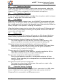
1
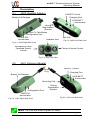
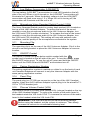
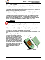
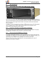
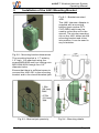
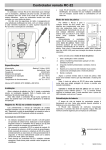
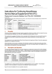
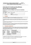
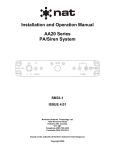
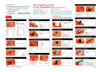
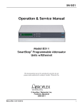
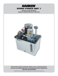
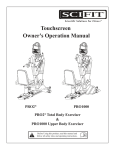
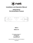
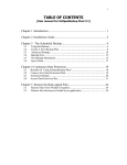
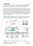
Wireless Intercom System Operating Manual Rev. B Page 1 wiJAC™ Wireless Intercom System Operating Manual Copyright 2013 Jupiter Avionics Corp. All rights reserved Jupiter Avionics Corporation (JAC) permits a single copy of this manual to be printed or downloaded for personal use. Any such electronic or printed copy of this manual must contain the complete text of this copyright notice. Any unauthorized commercial distribution of this manual is strictly prohibited. Except as described above, no part of this manual may be reproduced, copied, transmitted, disseminated, downloaded, or stored in any storage medium for any purpose without the express prior written consent of JAC. IMPORTANT: Information in this manual is subject to change without notice. To confirm the current revision status of this manual, visit the JAC website: www.jupiteravionics.com Rev A B Date Jun 2013 Sep 2013 Prepared: MPB Rev. B Record of Revisions Description Checked: ECR 1964/5 2270 Approved: JAC JAC 09-24-13 09-24-13 SRM KDV Page i wiJAC™ Wireless Intercom System Operating Manual Table of Contents 1 2 3 Introduction ................................................................................................. 1 Overview ...................................................................................................... 1 Description .................................................................................................. 2 3.1 JA60 Headset Adapter.......................................................................... 2 3.2 JA61 Intercom Adapter ......................................................................... 2 3.3 Battery Charge Annunciators ................................................................ 3 3.4 Battery Lid Release .............................................................................. 3 3.5 Belt Clip ................................................................................................ 3 3.6 Charging Port (PWR) ............................................................................ 3 3.7 Configuration Port (IO).......................................................................... 3 3.8 Headset Jack........................................................................................ 3 3.9 Low Battery Annunciator (LOW BATT) ................................................. 4 3.10 Microphone Voice Operated Switch Control (VOX) ............................... 4 3.11 Mounting Clip ....................................................................................... 4 3.12 ON/OFF Control ................................................................................... 4 3.13 Pairing Registration Number ................................................................. 4 3.14 Panel Plug ............................................................................................ 4 3.15 Phones Volume Control (VOL).............................................................. 4 3.16 Power On Annunciator (PWR ON) ........................................................ 5 3.17 Push to Talk Button (PTT) .................................................................... 5 4 Unpacking .................................................................................................... 5 5 Set-up and Connection ............................................................................... 5 5.1 Verify Operating Region ....................................................................... 5 5.2 Verify Pairing Registration Number ....................................................... 5 5.3 Insert Batteries ..................................................................................... 5 5.4 Attach Connectors to Aircraft and Headset ........................................... 5 5.5 Turn On Adapters and Verify Connection.............................................. 6 5.5 Verify Audio Operation.......................................................................... 6 6 Operation ..................................................................................................... 6 6.1 Overview .............................................................................................. 6 6.2 Listening Operation .............................................................................. 6 6.3 VOX Speaking Operation ..................................................................... 6 6.4 PTT Speaking Operation ...................................................................... 7 6.5 Live Speaking Operation ...................................................................... 7 6.6 Low Battery .......................................................................................... 7 6.7 Battery Life ........................................................................................... 7 6.8 Operation during Charging.................................................................... 7 6.9 Loss of Audio........................................................................................ 8 7 Batteries....................................................................................................... 8 7.1 Replacing the Batteries ......................................................................... 8 7.2 Charging Batteries in the Unit ............................................................... 9 7.3 Charging Operation – via Battery Charger ............................................ 9 7.4 Battery Care and Maintenance ............................................................. 9 8 Accessories ............................................................................................... 10 8.1 JA72-006 Glove Box with USB Power Output ..................................... 10 8.2 ProCS™ Product Configuration Software ........................................... 10 8.3 Recommended Battery Charger ......................................................... 10 9 Installation of the JA61 Mounting Bracket............................................... 11 10 Specifications ............................................................................................ 12 10.1 Mechanical ......................................................................................... 12 10.2 Electrical ............................................................................................. 12 10.3 Environmental .................................................................................... 12 10.4 Other .................................................................................................. 12 11 FCC Compliance Statement...................................................................... 13 12 Warranty .................................................................................................... 14 Rev. B Page ii wiJAC™ Wireless Intercom System Operating Manual 1 Introduction The wiJAC™ Wireless Intercom System provides a wireless full-duplex audio link between the aircraft’s audio system and the user’s headset. The wiJAC system allows access to the same functions of the audio system as are available when the headset is connected to the panel jack. This manual describes the: wiJAC-001 Wireless Intercom System - N America, consisting of JA60-001 Wireless Aircraft Headset Adapter and the JA61-001 Wireless Aircraft Intercom Adapter 2 Overview The JA61 Intercom Adapter has a plug that is inserted into a jack in the aircraft where the headset is normally connected. A headset is inserted into the jack on the JA60 Headset Adapter, which is clipped to the user's belt or placed in a pocket. Headset and audio panel are not included. Typical wiJAC™ Set Up JA60-001 Headset Adapter (Connected to user's headset) Rev B JA61-001 Intercom Adapter (Plugged in to aircraft headset jack) Page 1 wiJAC™ Wireless Intercom System Operating Manual 3 Description 3.1 JA60 Headset Adapter ON/OFF Control Charging Port Battery Lid Release LOW BATT Annunciator Pairing Registration Number Push To Talk Button Configuration Port Belt Clip PWR ON Annunciator Headset Jack Fig 3-2, JA60 Left Side View Fig 3-1, JA60 Right Side View Microphone Voice Operated Switch Control Phones Volume Control Fig 3-3, JA60 Top View 3.2 JA61 Intercom Adapter ON/OFF Control Panel Plug Charging Port Battery Lid Release LOW BATT Annunciator Mounting Clip Configuration Port Pairing Registration Number PWR ON Annunciator Fig 3-4, JA61 Right Side View Fig 3-5, JA61 Left Side View Note: The units are shown in green for clarity. Rev B Page 2 wiJAC™ Wireless Intercom System Operating Manual 3.3 Battery Charge Annunciators The Fast Charge annunciator is a red light emitting diode (LED) under the Charging Port cover above the Charging Port connector. The Fast Charge annunciator is illuminated when the batteries are being charged at the maximum change current. The Top Off Charge annunciator is a green LED under the Charging Port cover below the Charging Port connector. The Top Off Charge annunciator is illuminated when the batteries are being charged at the minimum charge current. 3.4 Battery Lid Release The battery lid release is a lever on the front of the unit recessed into the battery lid. To remove the battery lid and access to the batteries, push the release level upwards and then gently pry the lid away from the unit. 3.5 Belt Clip The belt clip is on the rear of the JA60 Headset Adapter. Clip it to your belt or place it in another secure location. 3.6 Charging Port (PWR) The Charging Port is a Micro-USB connector with a cover labeled PWR (power) on the left side of the unit. To charge NiMH batteries, connect a USB (Universal Serial Bus)to Micro USB cable from the Charging Port to a USB power source. WARNING: If non-NiMH and non-NiCad batteries are installed, do not connect the Charging Port to a USB power source. Charging battery types other than NiMH or NiCad may cause the batteries to leak or explode and cause damage or injury. 3.7 Configuration Port (IO) The configuration port is a 3.5 mm 4 pole connector with a flexible cover labeled IO (input / output) located on the right side of the unit. This port is used during maintenance. The Headset and Intercom Adapters are factory configured with default settings that are suitable for most general aviation requirements. If it is necessary to change the phones/microphone input /output settings, this can be performed by a JAC dealer. Find your nearest dealer from the Dealers section of the JAC website – www.jupiteravionics.com. 3.8 Headset Jack The headset jack is a TJT120 type connector on the top of the JA60 headset adapter. Insert a U-174/U or U93A/U type Headset plug in to the JA60 Headset Adapter's headset jack. Rev B Page 3 wiJAC™ Wireless Intercom System Operating Manual 3.9 Low Battery Annunciator (LOW BATT) The low battery (LOW BATT) annunciator is a red LED located on the left side of the unit. When a unit is turned on, the LOW BATT annunciator will illuminate for 2 seconds. When the battery voltage is low the LOW BATT annunciator will flash once every 1.5 s. When the unit is turning off, the annunciator will illuminate until the unit is off. 3.10 Microphone Voice Operated Switch Control (VOX) The Voice Operated Switch control is a rotary knob marked VOX located on the top of the JA60 Headset Adapter. To reduce the level of the sound needed to route the microphone audio to the JA61 Intercom Adapter, turn the VOX knob CCW (counter-clockwise). To increase the level of the sound needed to route the microphone audio to the JA61 Intercom Adapter, turn the VOX knob CW (clockwise). This setting will vary with ambient noise conditions, and the quality of the microphones connected to the system. 3.11 Mounting Clip The mounting clip is on the rear of the JA61 Intercom Adapter. Clip it to the aircraft's mounting bracket or place the JA61 Intercom Adapter in a secure location. 3.12 ON/OFF Control The ON/OFF control is a push button switch marked with the symbol and is located on the left side of the unit. To turn the unit on, press the ON/OFF button once. To turn the unit off, press and hold the ON/OFF button until the PWR ON and LOW BATT annunciators turn off. 3.13 Pairing Registration Number The pairing registration number is marked on a label in on the back of each unit. Headset Adapters will connect to only the Intercom Adapter with the same paring registration number. 3.14 Panel Plug The panel plug is a TP120 type connector on the top of the JA61 headset adapter. Insert the JA61 Intercom Adapter's panel plug in to the aircraft's TJ120 or TJT120 headset jack. 3.15 Phones Volume Control (VOL) The volume control is a rotary knob marked VOL (volume) located on the top of the JA60 Headset Adapter. To reduce the volume of the audio heard in the headset rotate the VOL knob CCW. To increase the volume of the audio heard in the headset rotate the VOL knob CW. WARNING: Loud noise and sound can cause hearing damage. Before using the headset, set the volume to minimum. Then slowly increase the volume to a comfortable listening level. Rev B Page 4 wiJAC™ Wireless Intercom System Operating Manual 3.16 Power On Annunciator (PWR ON) The power on (PWR ON) annunciator is a green LED located on the right side of the unit. When a unit is turned on, the PWR ON annunciator will illuminate for 2 seconds. When the unit is searching for its paired unit the PWR ON annunciator will triple-flash every 1.5 seconds. When the unit is connecting to its paired unit, the annunciator will double-flash every 1.5 s. When the unit is connected to its paired unit, the annunciator will single flash every 1.5 s. When the unit is turning off, the annunciator will illuminate until the unit is off. 3.17 Push to Talk Button (PTT) The Push To Talk button is a push button switch marked PTT and is located on the right side of the JA60 Headset Adapter. To route microphone audio to the JA61 Intercom Adapter, press and hold the PTT button. 4 Unpacking Unpack the box carefully, and ensure that it contains the following: one ea. Wireless Aircraft Headset Adapter, JAC P/N JA60-001 one ea. Wireless Aircraft Intercom Adapter, JAC P/N JA61-001 one ea. Mounting Bracket, JAC P/N PLT-CLIP-0004 two pkg. of AAA rechargeable batteries, JAC P/N MSC-BATT-AAA1 two ea. USB to Micro USB cables, JAC P/N CAB-USB-0003 one wiJAC™ Quick Start Guide, JAC P/N DOC-GUID-WIJAC 5 Set-up and Connection 5.1 Verify Operating Region The wiJAC-001 Wireless Intercom System operates using radio frequencies that are authorized by government regulatory agencies. Ensure the region in which you are operating the units matches the region marked on a label on the back of each unit. 5.2 Verify Pairing Registration Number The wiJAC-001 Wireless Intercom System consists of one set of paired Adapters. The Headset Adapter must be paired with the Intercom Adapter. Ensure that the same three character Pairing Registration Number is marked on a label on the back of each unit. 5.3 Insert Batteries Ensure the batteries in both units are fully charged and installed in the battery compartment with the correct polarity and the battery lid is secured. 5.4 Attach Connectors to Aircraft and Headset Connect the JA61 Intercom Adapter plug to a TJ-120 or TJT120 aircraft intercom headset jack. Rev B Page 5 wiJAC™ Wireless Intercom System Operating Manual Insert a headset with a U-174/U or U93A/U type plug into the JA60 Headset Adapter jack. 5.5 Turn On Adapters and Verify Connection On the JA60 Headset Adapter, turn the VOL knob fully CCW to minimum. Turn on the JA60 Headset Adapter and the JA61 Intercom Adapter. On both units the PWR ON and LOW BATT annunciators will illuminate for two seconds. Then the PWR ON annunciators will flash every 1.5 seconds. When the units are connected, the PWR ON annunciators on both units will flash once every 1.5 seconds. 5.5 Verify Audio Operation Set the aircraft audio system's VOX mode to live or key the aircraft audio system's ICS PTT for the headset connection used by the JA61 Intercom Adapter. Adjust the JA60 Headset Adapter's VOX control to fully CCW and the VOL control to achieve a comfortable listening level, confirm that the microphone audio is live—all microphone audio is heard in the phones. Confirm that the audio level increases as the VOL control is rotated CW and decreases as the VOL control is rotated CCW. Adjust the Headset Adapter's VOX control to fully CW and confirm that the microphone audio is off. Press the Headset Adapter's PTT button and confirm that microphone audio is heard in the phones. Adjust the Headset Adapter's VOX control for a comfortable speaking level and return the aircraft audio system's controls to the previous settings. 6 Operation 6.1 Overview When both units are turned on and connected, phones audio from the aircraft audio system is transmitted from the Intercom Adapter, Received by the Headset Adapter and output on the headset's phones. Microphone audio from the headset's microphone is transmitted from the Headset Adapter, received by the Intercom Adapter and output to the aircraft's audio system as microphone audio. 6.2 Listening Operation The Headset Adapter's Phones Volume controls the level of audio heard in the headset's ear phones. As background noise levels change, the volume may need to be adjusted. 6.3 VOX Speaking Operation To use the JA60 Headset Adapter hands-free, adjust the VOX control such that the microphone audio is turned on when speaking in to the headset's microphone at a comfortable level, or at a level to keep the background noise from turning on the microphone audio. Rev B Page 6 wiJAC™ Wireless Intercom System Operating Manual 6.4 PTT Speaking Operation To use the JA60 Headset Adapter in high-noise environments, adjust the VOX control fully CW. To communicate, press and hold the JA60 Headset Adapter's PTT button and speak in to the headset's microphone. 6.5 Live Speaking Operation To use the JA60 Headset Adapter, such that the microphone audio is always turned on, adjust the VOX control fully CCW. 6.6 Low Battery When the unit's battery charge is low, the LOW BATT annunciator will triple flash every 1.5 seconds. When the JA60 Headset Adapter battery charge is low, a triple-beep will be heard in the headset every three minutes. When the battery charge is low replace or recharge the batteries. When the battery charge level is critical, the unit will turn off. When one unit is off the other unit will begin searching for its paired unit and its PWR ON annunciator will triple flash. 6.7 Battery Life The duration the wiJAC-001 system will operate on fully charged batteries, before battery replacement is required, depends on the following factors: Distance between Headset Adapter and Intercom Adapter: The closer together the units are the lower the radio frequency (RF) power required for connection and will increase the battery life. Obstacles between the Headset Adapter and Intercom Adapter: Reducing the aircraft metal structures, human bodies, cargo and other obstacles between the units will reduce the RF power needed for connection and increase the battery life. Charge capacity of the batteries installed: The higher the capacity of the batteries, typically specified as 500 to 1000 mAh (milliamp-hours), the longer the battery life. The type and temperature of the batteries installed: During low temperature operation, rechargeable batteries will lose capacity. When operating in low temperatures use alkaline batteries for a longer battery life. The phones volume level and usage rate: The lower the volume level and the less often audio is output to the phones the longer the battery life. 6.8 Operation during Charging The units will operate while the Charging Port is connected to a USB power source. Additional noise may be heard on the audio system while the Charging Port is connected to a USB power source. Rev B Page 7 wiJAC™ Wireless Intercom System Operating Manual 6.9 Loss of Audio If there is no audio heard in the headset, check the PWR ON annunciator on the JA60 Headset Adapter and the JA61 Intercom Adapter. If a unit is off, turn it on and verify connection and operation. If the battery charge is low, replace or recharge the batteries or connect the headset directly to the aircraft audio system. If audio is unintelligible, turn off and remove the JA60 Headset Adapter and the JA61 Intercom Adapter and connect the headset directly to the audio panel. If another aircraft system is experiencing a fault, turn off and remove the JA60 Headset Adapter and the JA61 Intercom Adapter and connect the headset directly to the audio panel. Do not use the JA60 Headset Adapter and the JA61 Intercom Adapter if they are the cause of the fault. 7 Batteries WARNING: If non-NiMH and non-NiCad batteries are installed, do not connect the Charging Port to a USB power source. Charging battery types other than NiMH or NiCad may cause the batteries to leak or explode and cause damage or injury. JAC recommends Duracell 800 mAh (or higher) NiMH or Duracell alkaline batteries for use in the wiJAC™ system to obtain the typical battery life. The JA60 and JA61 each require three AAA batteries. Removal of the batteries WILL NOT change any internal configuration of the unit. 7.1 Replacing the Batteries To replace the batteries (both units the same), remove the battery cover by pressing the battery lid release upwards, lifting the lower end of the cover, and then gently pry the lid up and away from the body to release the two tabs from the retaining slots. Retaining Tabs Remove the batteries and insert fully charged batteries matching the polarity marked on the battery holder. Battery Lid Release Rev B Page 8 wiJAC™ Wireless Intercom System Operating Manual 7.2 Charging Batteries in the Unit To charge rechargeable batteries in the unit, connect the Charging Port to a USB power source using the USB to Micro-USB cable (CAB-USB-0003). It should be possible to charge the unit via most USB power sources but this cannot be guaranteed for any products not made or purchased by JAC. Where space allows, JAC recommends the JAC JA72-006 6 Dzus Glove Box with USB connector (see section 8.1) Note: The batteries will charge when a unit is on or off. Charging Operation – via Battery Charger 7.3 The batteries may be removed from the unit for charging in a separate battery charger. See section 8. Removal of the batteries WILL NOT change any internal configuration of the unit. 7.4 Battery Care and Maintenance To look after and extend the life of a rechargeable NiMH battery: CAUTION: Follow these guidelines to prolong battery life and minimise the risk of unit malfunction. Do not leave battery uncharged for long periods of time. Do not leave battery charging for extended periods (more than 48 hours) To ensure that the unit functions correctly, insert the new batteries with the positive and negative poles aligned as indicated in the battery compartment. When replacing the batteries, use only new or fully charged batteries. Do not mix old and new batteries as this can cause battery leakage and/or damage to the unit. Do not mix battery types. WARNING: Follow these guidelines to prolong battery life, and minimise the risk of fire, chemical burns, electrolyte leaks and/or injury. FOLLOW the battery manufacturer's instructions for battery care and disposal. DO NOT use sharp objects to remove the batteries. DO NOT disassemble, puncture, burn or in any other way damage the batteries. DO NOT let children handle the batteries. USE ONLY recommended battery chargers. USE ONLY recommended replacement batteries. Rev B Page 9 wiJAC™ Wireless Intercom System Operating Manual 8 Accessories 8.1 JA72-006 Glove Box with USB Power Output The JA72 Glove Box with USB Charger allows the aircraft owner/operator to use an unused portion of the instrument panel for storage. The interior of the glove box has a soft, high friction finish to minimize noise and movement due to vibration. A USB 2.0 Type A receptacle provides a USB power source of 5 Vdc power up to 2 Amps, and a 3.5mm stereo jack enables music players to be connected to the aircraft's audio system. 8.2 ProCS™ Product Configuration Software Approved dealers and installers will be provided with the ProCS™ Product Configuration Software and a ProCS™ connection cable. 8.3 Recommended Battery Charger To charge AAA NiMH batteries, JAC recommends the charger should have individual cell charging (so that three batteries may be charged at once), an automatic shut of feature and a charge time of two to six hours. Always follow the battery manufacturer’s recommendations for use of batteries and battery chargers. Rev B Page 10 wiJAC™ Wireless Intercom System Operating Manual 9 Installation of the JA61 Mounting Bracket Fig 9-1 - Bracket-mounted JA61 The JA61 Intercom Adapter is supplied with a mounting bracket (part number PLTCLIP-0004) which may be used to mount the unit in the aircraft. The circular mounting clip on the JA61 slides into the mounting bracket and clicks into position. It can be used in any orientation. Fig 9-2 - Mounting bracket dimensions The mounting bracket is 1.7" wide by 1.2" high. It is attached using four screws MS24693 and four locking nuts MS21044-NO4 through four 1/8" diameter holes. Ensure that there is sufficient space to connect the JA61-001 to the mounting bracket and to the aircraft headset jack. Fig 9-3 - Bracket/jack proximity Rev B Fig 9-4 - Mounting details Page 11 wiJAC™ Wireless Intercom System Operating Manual 10 Specifications 10.1 Mechanical Height Overall depth Width Weight (with Batteries) Mounting Headset Connections Enclosure Material Configuration Port Charging Port 10.2 JA60-001 JA61-001 4.79 in (122 mm) max 8.15 in (207.0 mm) max 1.10 in (27.9 mm) max 1.10 in (27.9 mm) max 2.05 in (52.1 mm) max 2.05 in (52.1 mm) max 0.39 lb (178 g) max 0.33 lb (149 g) max Belt clip Mounting bracket 4 pole TJT-120 jack 4 pole TP-120 plug Polycarbonate 4 pole 3.5mm jack USB Micro-AB 2.0 Electrical JA60-001 Default MICROPHONE INPUT level Microphone Type Default PHONES OUTPUT level Phones Type Charging Port JA61-001 Default MICROPHONE OUTPUT level Default PHONES INPUT level Charging Port 10.3 300 mVrms 4.50 Vrms into 600 Ω 5 Vdc @ 200 mA JA60-001 -15 to +50 25,000 95 6 g, 20 JA61-001 °C ft %RH (48 hours) g (for 11 ms) Other JA60-001 Battery Life Battery Quick Charge Duration Battery Top-Up Charge Duration Low Battery Notice Duration Range Region of Operation Rev B mVrms Ω Amplified Dynamic Vrms into 150 Ω Ω Vdc @ 200 mA Environmental Operating Temperature Altitude Humidity Shock, Crash Safety 10.4 250 150 4.00 150 5 JA61-001 6 to 8 h (typical) 4h 48 h max 15 minutes 100 meters (typical) North America Page 12 wiJAC™ Wireless Intercom System Operating Manual 11 FCC Compliance Statement This device complies with Part 15 of the FCC Rules. Operation is subject to the following two conditions: 1. 2. this device may not cause harmful interference, and this device must accept any interference received, including interference that may cause undesired operation of the device. Module transmetteur ID IC: 9576A-SC14A Son fonctionnement est soumis aux deux conditions suivantes: 1. 2. cet appareil ne doit pas causer d’interférences nuisibles et cet appareil doit accepter toute interférence reçue, y compris les interférences qui peuvent perturber le fonctionnement. Changes or modifications to the equipment not expressly approved by the Party responsible for compliance could void the user's authority to operate the equipment. NOTE: This equipment has been tested and found to comply with the limits for a Class B digital device, pursuant to Part 15 of the FCC Rules. These limits are designed to provide reasonable protection against harmful interference in a residential installation. This equipment generates, uses and radiates radio frequency energy and, if not installed and used in accordance with the instructions, may cause harmful interference to radio communications. There is no guarantee that interference will not occur in a particular installation. If this equipment does cause harmful interference to radio or television reception, which can be determined by turning the equipment off and on, the user is encouraged to try to correct the interference by one or more of the following measures: Reorient or relocate the receiving antenna Increase the separation between the equipment and the receiver. Connect the equipment into an outlet on a circuit different from that to which the receiver is connected. Consult the dealer or an experienced radio/TV technician for help. Privacy of communications may not be ensured when using this equipment. Rev B Page 13 wiJAC™ Wireless Intercom System Operating Manual 12 Warranty Locate and complete the online warranty registration form from the JAC website: www.jupiteravionics.com/warrantyregistration These products manufactured by JAC are warranted to be free of defects in workmanship or performance for 1 year from the date of purchase. This warranty covers the cost of all materials and labour to repair or replace the unit, but does not include the cost of transporting the defective unit to and from JAC or its designated warranty repair centre. This warranty does not cover failures due to abuse, misuse, accident, incorrect battery use/installation, or unauthorized alteration or repairs. Contact JAC for any questions regarding this warranty and how it applies to your unit(s). JAC is the final arbiter concerning warranty issues. Contact JAC for a Returned Materials Authorisation Form (RMA) prior to shipping any products for repair. This form can be downloaded from our website at www.jupiteravionics.com/dealersrmaform Rev B Page 14 Jupiter Avionics Corporation 1959 Kirschner Road Kelowna BC V1Y 4N7 Canada Tel: 778-478-2232 Toll-Free: 855-478-2232 www.jupiteravionics.com