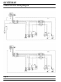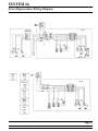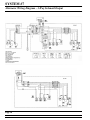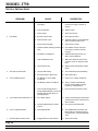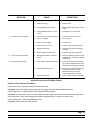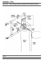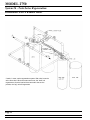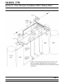
1
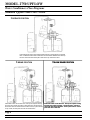
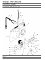
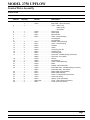
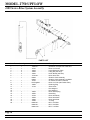
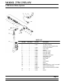
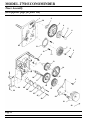
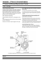
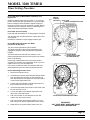
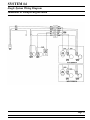
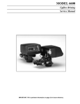
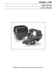
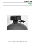
MODEL 2750 UPFLOW CONTROL VALVE
Service Manual
IMPORTANT: Fill in pertinent information on page 2 for future reference.
MODEL 2750
Job Specification Sheet
• JOB NO. __________________________________________________________
• *MODEL NO. ______________________________________________________
• WATER TEST ______________________________________________________
• CAPACITY PER UNIT ____________ MAX. ___________PER REGENERATION
• MINERAL TANK SIZE DIA.________ HEIGHT_________
• BRINE TANK SIZE & SALT SETTING PER REGENERATION:
•
_________________________________________________________________
* 2750 CONTROL VALVE SPECIFICATIONS
1. Type of Timer (see pages 16, 17, & 18)
A. 7 day or 12 day
B. * 310 to 5,2700 gallon meter or
* 1,550 to 26,350 gallon meter
* Other ______________________________________________________
C. Meter Wiring Package
1) System #4 - 1 tank; 1 meter; immediate or delayed regeneration
2) System #5 - 2 tanks; 2 meters; interlock
3) System #6 - 2 tanks; 1 meter; series regeneration
4) System #7 - 2 tanks; 1 meter; alternator
2. Timer Program Settings (see pages 18 and 19)
A. Backwash _______________________ min.
B. Brine & Slow Rinse ________________ min.
C. Rapid Rinse ______________________ min.
D. Brine Tank Refill___________________ min.
3. Drain Line Flow Controller ______________ gpm
4. Brine Line Flow Controller ______________ gpm
5. Injector Size #________________________
6. Service Valve Operation Units (SVO)
Size of Service Valve __________________
•
Page 2
Printed in U.S.A.
MODEL 2750
General Commercial Pre-Installation Check List
WATER PRESSURE: A minimum of 25 pounds of water pressure is required for regeneration valve to operate
effectively.
ELECTRICAL FACILITIES: A continuous 110 volt, 60 Hertz current supply is required. Make certain the current supply
is always hot and cannot be turned off with another switch. (Other voltages available.)
EXISTING PLUMBING: Condition of existing plumbing should be free from lime and iron buildup. Piping that is built up
heavily with lime and/or iron should be replaced. If piping is clogged with iron, a separate iron filter unit should be
installed ahead of the water softener.
LOCATION OF SOFTENER AND DRAIN: The softener should be located close to a drain.
BY-PASS VALVES: Always provide for the installation of a by-pass valve.
CAUTION: Water pressure is not to exceed 120 p.s.i., water temperature is not to exceed 100°F, and the unit cannot be
subjected to freezing conditions.
INSTALLATION INSTRUCTIONS
1. Place the softener tank where you want to install the unit making sure the unit is level and on a firm base.
(Maximum 4 feet apart for twin units.)
2. All plumbing should be done in accordance with local plumbing codes. The pipe size for the drain line should be the
same size as the drain line flow control female connection. Water meters are to be installed on soft water outlets.
Twin units with (1) one meter shall be installed on common soft water outlet of units.
3. Solder joints near the drain must be done prior to connecting the Drain Line Flow Control filling. Leave at least 6″
between the DLFC and solder joints when soldering when the pipes are connected on the DLFC. Failure to do this
could cause interior damage to the DLFC.
4. Teflon tape is the only sealant to be used on the drain fitting. The drain from twin units may be run through a
common line.
5. Make sure that the floor is clean beneath the salt storage tank and that it is level.
6. Place approximately 1″ of water above the grid plate (if used) in your salt tank. Salt may be placed in the unit at this
time.
7. On units with a by-pass, place in by-pass position. Turn on the main water supply. Open a cold soft water tap
nearby and let run a few minutes or until the system is free from foreign material (usually solder) that may have
resulted from the installation.
8. Place the by-pass in service position.
9. Manually index the softener control into “service” position and let water flow into the mineral tank. When water flow
stops, open a cold water tap nearby and let run until air pressure is relieved.
10. Electrical: All electrical connections must be connected according to codes. Use electrical conduit if applicable.
Remote meter systems and Twin meter system wiring diagrams are on page 22. Plug into power supply.
Page 3
Printed in U.S.A.
MODEL 2750 UPFLOW
Water Conditioners Flow Diagrams
Standard Upflow Cams 19887/19888
1 SERVICE POSITION
Hard water enters unit at valve inlet and flows down thru the mineral in the mineral
tank. Conditioned water enters center tube thru the bottom distributor then flows up
thru the center tube around the piston and out the top outlet of the valve.
2 BRINE POSITION
3 SLOW RINSE POSITION
Hard water enters unit at valve inlet - flows up into injector housing
and down thru nozzle and orifice to draw brine from the brine tank brine flows down the center tube thru bottom of tank, up thru mineral
to top of tank, around piston and out thru the drain line.
Hard water enters unit at valve inlet - flows up into injector housing
and down thru nozzle and orifice - around the piston - down thru
center tube thru bottom distributor - flows up thru mineral - around
piston and out thru drain line.
Page 4
Printed in U.S.A.
4 BACK WASH POSITION
Hard water enters unit at valve inlet - flows thru piston - down center
tube - thru bottom distributor and up thru the mineral - around the
piston and out the drain line.
5 RAPID RINSE
6 BRINE TANK FILL POSITION
Hard water flows directly from inlet down thru mineral into center
tube bottom distributor and up thru center tube - around piston and
out thru the drain line.
Hard water enters unit at valve inlet - flows up thru the injector
housing- thru the brine valve to fill the brine tank.
Page 5
Printed in U.S.A.
MODEL 2750 UPFLOW
Control Drive Assembly
(See opposite page for parts list)
Page 6
Printed in U.S.A.
MODEL 2750 UPFLOW
Control Drive Assembly
Parts List
Item No.
Quantity
Part No.
Description
1 . . . . . . . . . . . .1 . . . . . . . . . . . . 14884 . . . . . . . . . . . . . . . . Back Plate
1 . . . . . . . . . . . . 15156 . . . . . . . . . . . . . . . . Back Plate - SVO (not shown)
2 . . . . . . . . . . . .1. . . . . . . . . . . . . . . . . . . . . . . . . . . . . . . . . . Timer -3200 7 Day
-3200 12 Day
-3210 Meter
3 . . . . . . . . . . . .1 . . . . . . . . . . . . 11838 . . . . . . . . . . . . . . . . Power Cord
4 . . . . . . . . . . . .1 . . . . . . . . . . . . 13547 . . . . . . . . . . . . . . . . Strain Relief
5 . . . . . . . . . . . .1 . . . . . . . . . . . . 11667 . . . . . . . . . . . . . . . . Wire Harness
7 . . . . . . . . . . . .5 . . . . . . . . . . . . 10872 . . . . . . . . . . . . . . . . Screw - Motor Mounting
8 . . . . . . . . . . . . . . . . . . . . . . . . . . . . . . . . . . . . . . . . . . . . . . . Not Assigned
9 . . . . . . . . . . . . . . . . . . . . . . . . . . . . . . . . . . . . . . . . . . . . . . . Not Assigned
10 . . . . . . . . . . .1 . . . . . . . . . . . . 10774 . . . . . . . . . . . . . . . . Bracket - Motor Mounting
11 . . . . . . . . . . .2 . . . . . . . . . . . . 10231 . . . . . . . . . . . . . . . . Screw - Drive Mounting
12 . . . . . . . . . . .2 . . . . . . . . . . . . 10302 . . . . . . . . . . . . . . . . Insulator
13 . . . . . . . . . . .2 . . . . . . . . . . . . 10218 . . . . . . . . . . . . . . . . Switch
14 . . . . . . . . . . .1 . . . . . . . . . . . . 10909 . . . . . . . . . . . . . . . . Connecting Link Pin
15 . . . . . . . . . . .3 . . . . . . . . . . . . 10250 . . . . . . . . . . . . . . . . Retaining Ring
16 . . . . . . . . . . .1 . . . . . . . . . . . . 10621 . . . . . . . . . . . . . . . . Connecting Link
17 . . . . . . . . . . .1 . . . . . . . . . . . . 19750 . . . . . . . . . . . . . . . . Drive Cam - Variable Brining (not shown)
1 . . . . . . . . . . . . 19888 . . . . . . . . . . . . . . . . Drive Cam - Std. Upflow
18 . . . . . . . . . . .2 . . . . . . . . . . . . 10338 . . . . . . . . . . . . . . . . Roll Pin
19 . . . . . . . . . . .1 . . . . . . . . . . . . 13366 . . . . . . . . . . . . . . . . Drive Bearing
20 . . . . . . . . . . .2 . . . . . . . . . . . . 14923 . . . . . . . . . . . . . . . . Screw - Switch Mounting
21 . . . . . . . . . . .1 . . . . . . . . . . . . 10769 . . . . . . . . . . . . . . . . Motor
22 . . . . . . . . . . .1 . . . . . . . . . . . . 11826 . . . . . . . . . . . . . . . . Bracket - Brine Valve Side
23 . . . . . . . . . . .1 . . . . . . . . . . . . 19749 . . . . . . . . . . . . . . . . Brine Valve Cam - Variable Brining (not shown)
1 . . . . . . . . . . . . 19887 . . . . . . . . . . . . . . . . Brine Valve Cam - Std. Upflow
24 . . . . . . . . . . .1 . . . . . . . . . . . . 15441 . . . . . . . . . . . . . . . . Meter Cable Guide Assembly
25 . . . . . . . . . . .1 . . . . . . . . . . . . 15513 . . . . . . . . . . . . . . . . Meter Cable Assembly
26 . . . . . . . . . . .2 . . . . . . . . . . . . 10300 . . . . . . . . . . . . . . . . Screw - Timer Mounting (not shown)
27 . . . . . . . . . . .2 . . . . . . . . . . . . 15742 . . . . . . . . . . . . . . . . Screw (not shown)
28 . . . . . . . . . . .2 . . . . . . . . . . . . 15833 . . . . . . . . . . . . . . . . Spacer, Cover (not shown)
29 . . . . . . . . . . .1 . . . . . . . . . . . . 19291-020. . . . . . . . . . . . . Cover, 1 Piece, Black (not shown)
30 . . . . . . . . . . .2 . . . . . . . . . . . . 19367 . . . . . . . . . . . . . . . . Screw, Cover (not shown)
Page 7
Printed in U.S.A.
MODEL 2750 UPFLOW
Control Valve with 1700 Injector
(See opposite page for parts list)
Page 8
Printed in U.S.A.
MODEL 2750 UPFLOW
Control Valve with 1700 Injector
Parts List
Item No.
No. Req’d.
Part No.
Description
1 . . . . . . . . . . . .1 . . . . . . . . . . . . 19401-01. . . . . . . . . . . . . .
2 . . . . . . . . . . . .6 . . . . . . . . . . . . 10545 . . . . . . . . . . . . . . . .
3 . . . . . . . . . . . .5 . . . . . . . . . . . . 11451 . . . . . . . . . . . . . . . .
4 . . . . . . . . . . . .1 . . . . . . . . . . . . 19454 . . . . . . . . . . . . . . . .
5 . . . . . . . . . . . .1 . . . . . . . . . . . . 14452 . . . . . . . . . . . . . . . .
6 . . . . . . . . . . . .1 . . . . . . . . . . . . 40078 . . . . . . . . . . . . . . . .
7 . . . . . . . . . . . .1 . . . . . . . . . . . . 10209 . . . . . . . . . . . . . . . .
8 . . . . . . . . . . . .1 . . . . . . . . . . . . 10598-03. . . . . . . . . . . . . .
9 . . . . . . . . . . . .1 . . . . . . . . . . . . 14805 . . . . . . . . . . . . . . . .
10 . . . . . . . . . . .1 . . . . . . . . . . . . 14802 . . . . . . . . . . . . . . . .
11 . . . . . . . . . . .1 . . . . . . . . . . . . 17777-02. . . . . . . . . . . . . .
12 . . . . . . . . . . .1 . . . . . . . . . . . . 14801 . . . . . . . . . . . . . . . .
13 . . . . . . . . . . .1 . . . . . . . . . . . . 19478 . . . . . . . . . . . . . . . .
14 . . . . . . . . . . .1 . . . . . . . . . . . . 19925 . . . . . . . . . . . . . . . .
15 . . . . . . . . . . .1 . . . . . . . . . . . . 16221 . . . . . . . . . . . . . . . .
16 . . . . . . . . . . .2 . . . . . . . . . . . . 19718 . . . . . . . . . . . . . . . .
17 . . . . . . . . . . .1 . . . . . . . . . . . . . . . . . . . . . . . . . . . . . . . . . .
18 . . . . . . . . . . .1 . . . . . . . . . . . . 15177 . . . . . . . . . . . . . . . .
19 . . . . . . . . . . .2 . . . . . . . . . . . . 11710 . . . . . . . . . . . . . . . .
20 . . . . . . . . . . .1 . . . . . . . . . . . . 11208 . . . . . . . . . . . . . . . .
21 . . . . . . . . . . .1 . . . . . . . . . . . . 12461-01. . . . . . . . . . . . . .
22 . . . . . . . . . . .1 . . . . . . . . . . . . 10381 . . . . . . . . . . . . . . . .
23 . . . . . . . . . . .1 . . . . . . . . . . . . 19457 . . . . . . . . . . . . . . . .
24 . . . . . . . . . . .2 . . . . . . . . . . . . 11224 . . . . . . . . . . . . . . . .
25 . . . . . . . . . . .1 . . . . . . . . . . . . 17776-02. . . . . . . . . . . . . .
26 . . . . . . . . . . .1 . . . . . . . . . . . . 10914 . . . . . . . . . . . . . . . .
27 . . . . . . . . . . .1 . . . . . . . . . . . . 10913 . . . . . . . . . . . . . . . .
28 . . . . . . . . . . .1 . . . . . . . . . . . . 19479 . . . . . . . . . . . . . . . .
29 . . . . . . . . . . .2 . . . . . . . . . . . . 19740 . . . . . . . . . . . . . . . .
30 . . . . . . . . . . .1 . . . . . . . . . . . . 10757 . . . . . . . . . . . . . . . .
31 . . . . . . . . . . .1 . . . . . . . . . . . . 19482 . . . . . . . . . . . . . . . .
19482-01. . . . . . . . . . . . . .
32 . . . . . . . . . . .1 . . . . . . . . . . . . 19452 . . . . . . . . . . . . . . . .
. . . . . . . . . . . . .1 . . . . . . . . . . . . 19925 . . . . . . . . . . . . . . . .
33 . . . . . . . . . . .1 . . . . . . . . . . . . 19464 . . . . . . . . . . . . . . . .
1 . . . . . . . . . . . . 19464-01. . . . . . . . . . . . . .
34 . . . . . . . . . . .1 . . . . . . . . . . . . 19462 . . . . . . . . . . . . . . . .
1 . . . . . . . . . . . . 19924 . . . . . . . . . . . . . . . .
35 . . . . . . . . . . .1 . . . . . . . . . . . . 19463 . . . . . . . . . . . . . . . .
36 . . . . . . . . . . .1 . . . . . . . . . . . . 18568 . . . . . . . . . . . . . . . .
37 . . . . . . . . . . .1 . . . . . . . . . . . . 14848 . . . . . . . . . . . . . . . .
38 . . . . . . . . . . .1 . . . . . . . . . . . . 18571 . . . . . . . . . . . . . . . .
39 . . . . . . . . . . .1 . . . . . . . . . . . . 18837 . . . . . . . . . . . . . . . .
1 . . . . . . . . . . . . 19917 . . . . . . . . . . . . . . . .
40 . . . . . . . . . . .1 . . . . . . . . . . . . 18570 . . . . . . . . . . . . . . . .
Valve Body
Seal
Spacer
Piston
Piston Rod
“O” Ring - End Plug
Quad Ring - Piston Rod
End Plug Assembly
Injector Body Gasket
Injector Throat1
Injector Body
Injector Nozzle
Injector Screen
Injector Cover Gasket
Air Disperser - 1600 Injector (not shown)
Screw- Injector Body
Washer - Flow Control (specify size)
Flow Control Housing
“O” Ring Base
“O” Ring Base
Adapter Base 2-1/2-8 Thd
“O” Ring-Top of Tank
Spacer, Long, Red
Screw - Valve Mounting
Injector Body
Injector Throat
Injector Nozzle
Injector Screen
Screw - Injector Body
End Spacer
Adapter Regulator - 1600
Adapter Regulator - 1700
Gasket, Adapter - 1600
Gasket, Adapter - 1700
Body, Regulator - 1600
Body, Regulator - 1700
Stem, Regulator-1600
Stem, Regulator- 1700
Seat, Regulator
Diaphragm, Regulator
Washer, Regulator
Retainer, Regulator
Spring, Regulator - 1600
Spring, Regulator- 1700
Cap, Regulator
Page 9
Printed in U.S.A.
MODEL 2750 UPFLOW
1600 Series Brine System Assembly
PARTS LIST
Item No.
Quantity
1. . . . . . . . . . . .
2. . . . . . . . . . . .
3. . . . . . . . . . . .
4. . . . . . . . . . . .
5. . . . . . . . . . . .
6. . . . . . . . . . . .
7. . . . . . . . . . . .
Part No.
Description
1
1
2
3
3
1
1
. . . . . . . . . . . . 10328-01 . . . . . . . . . . . . . . 900 Elbow-1/4 Pipe Thd. to 3/8 Tube
. . . . . . . . . . . . 12767. . . . . . . . . . . . . . . . . Brine Line Screen
. . . . . . . . . . . . 10332. . . . . . . . . . . . . . . . . Insert Sleeve 3/8 Tube)
. . . . . . . . . . . . 10329. . . . . . . . . . . . . . . . . Fitting Nut (3/8 Tube)
. . . . . . . . . . . . 10330. . . . . . . . . . . . . . . . . Derlin Sleeve (3/8 Tube)
. . . . . . . . . . . . 14703-02 . . . . . . . . . . . . . . Brine Valve Tube
. . . . . . . . . . . . 60002. . . . . . . . . . . . . . . . . #500 Air Check Assembly
60003. . . . . . . . . . . . . . . . . #500 Air Check Assembly, Hot Water
8 . . . . . . . . . . . . 1 . . . . . . . . . . . . 12794. . . . . . . . . . . . . . . . . 90˚ Elbow-3/8 Tube to 3/8 Tube
9 . . . . . . . . . . . . 1 . . . . . . . . . . . . Not Supplied . . . . . . . . . . . Brine Line Tube (3/8 Flexible Tube)
10 . . . . . . . . . . . 1 . . . . . . . . . . . . 10250. . . . . . . . . . . . . . . . . Retaining Ring
11 . . . . . . . . . . . 1 . . . . . . . . . . . . 11749. . . . . . . . . . . . . . . . . Stem Guide
12 . . . . . . . . . . . . . . . . . . . . . . . . . . . . . . . . . . . . . . . . . . . . . . . Not Assigned
13 . . . . . . . . . . . . . . . . . . . . . . . . . . . . . . . . . . . . . . . . . . . . . . . Not Assigned
14 . . . . . . . . . . . 1 . . . . . . . . . . . . 10249. . . . . . . . . . . . . . . . . Brine Valve Spring
15 . . . . . . . . . . . 1 . . . . . . . . . . . . 12550. . . . . . . . . . . . . . . . . Quad Ring
16 . . . . . . . . . . . 1 . . . . . . . . . . . . 12748. . . . . . . . . . . . . . . . . Brine Valve Body
17 . . . . . . . . . . . 1 . . . . . . . . . . . . 12552. . . . . . . . . . . . . . . . . Brine Valve Stem
18 . . . . . . . . . . . 1 . . . . . . . . . . . . 12626. . . . . . . . . . . . . . . . . Brine Valve Seat
19 . . . . . . . . . . . 1 . . . . . . . . . . . . 11982. . . . . . . . . . . . . . . . . “O” Ring
20 . . . . . . . . . . . 1 . . . . . . . . . . . . 60020-25 . . . . . . . . . . . . . . BLFC .25 GPM
60020-50 . . . . . . . . . . . . . . BLFC .50 GPM
60020-100 . . . . . . . . . . . . . BLFC 1.0 GPM
Page 10
Printed in U.S.A.
MODEL 2750 UPFLOW
1700 Series Brine System
PARTS LIST
Item No.
No. Req’d.
1. . . . . . . . . . . .
2. . . . . . . . . . . .
3. . . . . . . . . . . .
4. . . . . . . . . . . .
5. . . . . . . . . . . .
6. . . . . . . . . . . .
7. . . . . . . . . . . .
8. . . . . . . . . . . .
9. . . . . . . . . . . .
10 . . . . . . . . . . .
11 . . . . . . . . . . .
12 . . . . . . . . . . .
13 . . . . . . . . . . .
14 . . . . . . . . . . .
15 . . . . . . . . . . .
16 . . . . . . . . . . .
17 . . . . . . . . . . .
18 . . . . . . . . . . .
19 . . . . . . . . . . .
Part No.
Description
1
1
1
1
2
1
1
1
1
1
1
1
1
2
2
2
1
1
1
. . . . . . . . . 14792 . . . . . . . . . .End Plug
. . . . . . . . . 13201 . . . . . . . . . .“O” Ring - End Plug
. . . . . . . . . . . . . . . . . . . . . . . . .Washer Flow Control (specify size)
. . . . . . . . . 14785 . . . . . . . . . .Flow Control Retainer
. . . . . . . . . 14811 . . . . . . . . . .Piston Seals
. . . . . . . . . 14798 . . . . . . . . . .Spacer
. . . . . . . . . 14795 . . . . . . . . . .Brine Valve Piston
. . . . . . . . . 14797 . . . . . . . . . .Brine Valve Stem
. . . . . . . . . 14790 . . . . . . . . . .Brine Valve Body
. . . . . . . . . 12550 . . . . . . . . . .Quad Ring - Brine Stem
. . . . . . . . . 15310 . . . . . . . . . .Spring-Brine Valve
. . . . . . . . . 10250 . . . . . . . . . .Retaining Ring
. . . . . . . . . 15517 . . . . . . . . . .Stem Guide
. . . . . . . . . 15415 . . . . . . . . . .Insert
. . . . . . . . . 15414 . . . . . . . . . .Nut & Sleeve
. . . . . . . . . 15413 . . . . . . . . . .Elbow
. . . . . . . . . 19682 . . . . . . . . . .Brine Tube
. . . . . . . . . 16977 . . . . . . . . . .Reducer Coupling, 1/2 NPT to 3/8 NPT
. . . . . . . . . 60009 . . . . . . . . . .#900 Air Check Assembly
60009-01. . . . . . . .#900 Air Check Assembly, Hot Water
20 . . . . . . . . . . . 2 . . . . . . . . . 16123 . . . . . . . . . .Nut
21 . . . . . . . . . . . 2 . . . . . . . . . 16124 . . . . . . . . . .Sleeve
Page 11
Printed in U.S.A.
MODEL 2750 ECONOMINDER
Timer Assembly
(See opposite page for parts list)
1
2
30
3
4
5
6
29
31
7
8
5
10
9
11
12
32
13
14
15
16
5
17
18
24
23
25
19
26
25
27
25
20
28
21
22
Page 12
Printed in U.S.A.
MODEL 2750 ECONOMINDER
Timer Assembly
Parts List
Item No.
No. Req’d.
Part No.
Description
1 . . . . . . . . . . . 1 . . . . . . . . . . . 113870 . . . . . . . . . . . . . .
2 . . . . . . . . . . . 1 . . . . . . . . . . . 13011 . . . . . . . . . . . . . . .
3 . . . . . . . . . . . 1 . . . . . . . . . . . 40096-24 . . . . . . . . . . . . .
40096-02 . . . . . . . . . . . . .
4 . . . . . . . . . . . 1 . . . . . . . . . . . 13886-01 . . . . . . . . . . . . .
5 . . . . . . . . . . . 5 . . . . . . . . . . . 13296 . . . . . . . . . . . . . . .
6 . . . . . . . . . . . 1 . . . . . . . . . . . 11999 . . . . . . . . . . . . . . .
7 . . . . . . . . . . . 1 . . . . . . . . . . . 14381 . . . . . . . . . . . . . . .
14860 . . . . . . . . . . . . . . .
8 . . . . . . . . . . . 1 . . . . . . . . . . . 13014 . . . . . . . . . . . . . . .
9 . . . . . . . . . . . 1 . . . . . . . . . . . 14265 . . . . . . . . . . . . . . .
10 . . . . . . . . . . 2 . . . . . . . . . . . 13311 . . . . . . . . . . . . . . .
11 . . . . . . . . . . 2 . . . . . . . . . . . 13300 . . . . . . . . . . . . . . .
12 . . . . . . . . . . 1 . . . . . . . . . . . 15424 . . . . . . . . . . . . . . .
13 . . . . . . . . . . 1 . . . . . . . . . . . 13911 . . . . . . . . . . . . . . .
14 . . . . . . . . . . 1 . . . . . . . . . . . 19210 . . . . . . . . . . . . . . .
15 . . . . . . . . . . 21 . . . . . . . . . . 15493 . . . . . . . . . . . . . . .
16 . . . . . . . . . . 1 . . . . . . . . . . . 13018 . . . . . . . . . . . . . . .
17 . . . . . . . . . . 1 . . . . . . . . . . . 13312 . . . . . . . . . . . . . . .
18 . . . . . . . . . . 1 . . . . . . . . . . . 13017 . . . . . . . . . . . . . . .
19 . . . . . . . . . . 1 . . . . . . . . . . . 13164 . . . . . . . . . . . . . . .
20 . . . . . . . . . . 1 . . . . . . . . . . . 13887 . . . . . . . . . . . . . . .
21 . . . . . . . . . . 1 . . . . . . . . . . . 18743 . . . . . . . . . . . . . . .
19659 . . . . . . . . . . . . . . .
22 . . . . . . . . . . 2 . . . . . . . . . . . 13278 . . . . . . . . . . . . . . .
23 . . . . . . . . . . 3 . . . . . . . . . . . 11384 . . . . . . . . . . . . . . .
24 . . . . . . . . . . 1 . . . . . . . . . . . 13881 . . . . . . . . . . . . . . .
25 . . . . . . . . . . 3 . . . . . . . . . . . 14087 . . . . . . . . . . . . . . .
26 . . . . . . . . . . 1 . . . . . . . . . . . 10896 . . . . . . . . . . . . . . .
27 . . . . . . . . . . 1 . . . . . . . . . . . 15320 . . . . . . . . . . . . . . .
28 . . . . . . . . . . 2 . . . . . . . . . . . 11413 . . . . . . . . . . . . . . .
29 . . . . . . . . . . 1 . . . . . . . . . . . 14007 . . . . . . . . . . . . . . .
30 . . . . . . . . . . 1 . . . . . . . . . . . 14045 . . . . . . . . . . . . . . .
31 . . . . . . . . . . 1 . . . . . . . . . . . 13864 . . . . . . . . . . . . . . .
32 . . . . . . . . . . 1 . . . . . . . . . . . 15066 . . . . . . . . . . . . . . .
Not Shown. . . . 1 . . . . . . . . . . . 13902 . . . . . . . . . . . . . . .
Not Shown. . . . 2 . . . . . . . . . . . 12681 . . . . . . . . . . . . . . .
Not Shown. . . . 1 . . . . . . . . . . . 15354-01 . . . . . . . . . . . . .
Timer Housing
Cycle Actuator Arm
24 Hour Gear Assembly, 12 Midnight
24 Hour Gear Assembly, 2 a.m.
Knob
Screw - Timer Knob and Motor Mtg. Plate
Button Decal
Skipper Wheel Assembly - 12 Day
Skipper Wheel Assembly - 7 Day
Regeneration Pointer
Spring Clip
Spring - Skipper Wheel Detent
Ball - 1/4 in. Dia. Skipper Wheel
Spring - Main Gear Detent
Main Drive Gear
Program Wheel
Roll Pin
Idler Shaft
Spring - Idler
Idler Gear
Drive Gear
Motor Mounting Plate
Motor - 120V., 60 Hz.
Motor - 24V., 60 Hz.
Screw - Motor Mounting
Screw - Timer Hinge & Ground Wire
Hinge Bracket
Insulator
Switch
Switch
Screw - Switch Mounting
Decal - Time of Day
Decal - Instructions
Skipper Wheel Ring
Ball 1/4 in. Dia. Main Gear
Harness
Wire Connector
Ground Wire
Page 13
Printed in U.S.A.
MODEL 2750 ECONOMINDER
1″ Commercial Demand Regeneration Control
Timer Settings
Typical Programming Procedure
Calculate the gallon capacity of the system, subtract the
necessary reserve requirement and set the appropriate
gallons available opposite the small white dot on the
program wheel gear. Note, drawing shows 10,000 gallon
setting. The capacity (gallons) arrow denotes remaining
gallons exclusive of calculated reserve.
How To Set The Time Of Day:
Press and hold the red button in to disengage the drive
gear.
Turn the large gear until the actual time of day is opposite
the time of day pointer
Release the red button to again engage the drive gear.
How To Manually Regenerate Your Water Conditioner
At Any Time:
Turn the manual regeneration knob clockwise.
This slight movement of the manual regeneration knob
engages the program wheel and starts the regeneration
program.
The black center knob will make one revolution in the
following approximately three hours and stop in the
position shown in the drawing.
Even though it takes three hours for this center knob to
complete one revolution, the regeneration cycle of your
unit might be set for only one half of this time.
In any event, conditioned water may be drawn after rinse
water stops flowing from the water conditioner drain line.
Immediate Regeneration Timers:
These timers do not have a 24 hour gear. Setting the
gallons on the program wheel and manual regeneration
procedure are the same as previous instructions.
* Immediate regeneration timers do not have 24 hour gear. No time of day can be set.
Page 14
Printed in U.S.A.
MODEL 3200 TIMER
Timer Setting Procedure
How To Set Days On Which Water Conditioner Is To
Regenerate:
Rotate the skipper wheel until the number “1” is at the red
pointer. Set the days that regeneration is to occur by sliding
tabs on the skipper wheel outward to expose trip fingers.
Each tab is one day. Finger at red pointer is tonight. Moving
clockwise from the red pointer, extend or retract fingers to
obtain the desired regeneration schedule.
SERVICE
POSITION
INDICATOR
24 HR. GEAR
MANUAL REGENERATION KNOB
How To Set The Time Of Day:
Press and hold the red button in to disengage the drive gear.
Turn the large gear until the actual time of day is at the time
of day pointer.
RED
POINTER
Release the red button to again engage the drive gear.
How To Manually Regenerate Your Water
Conditioner At Any Time:
Turn the manual regeneration knob clockwise.
This slight movement of the manual regeneration knob
engages the program wheel and starts the regeneration
program.
The black center knob will make one revolution in the
following approximately three hours and stop in the position
shown in the drawing.
RED TIME
SET BUTTON
SKIPPER WHEEL
(SHOWS EVERY OTHER
DAY REGENERATION)
Even though it takes three hours for this center knob to
complete one revolution, the regeneration cycle of your unit
might be set for only one half of this time.
In any event, conditioned water may be drawn after rinse
water stops flowing from the water conditioner drain line.
How to Adjust Regeneration Time:
1.
Disconnect the power source.
2.
Locate the three screws behind the manual regeneration
knob by pushing the red button in and rotating the 24
hour dial until each screw appears in the cut out portion
of the manual regeneration knob.
3.
Loosen each screw slightly to release the pressure on
the time plate from the 24 hour gear.
4.
Locate the regeneration time pointer on the inside of the
24 hour dial in the cut out.
5.
Turn the time plate so the desired regeneration time
aligns next to the raised arrow.
6.
Push the red button in and rotate the 24 hour dial.
Tighten each of the three screws.
7.
Push the red button and locate the pointer one more
time to ensure the desired regeneration time is correct.
8.
Reset the time of day and restore power to the unit.
3200 ADJUSTABLE REGENERATION TIMER
IMPORTANT!
SALT LEVEL MUST ALWAYS BE ABOVE
WATER LEVEL IN BRINE TANK.
Page 15
Printed in U.S.A.
MODEL 3000, 3200 & 3210 TIMER SERIES
Regenerating Cycle Program Setting Procedure
(Brine Tank Refill Separate From Rapid Rinse)
How To Set The Regeneration Cycle Program:
The regeneration cycle program on your water conditioner
has been factory preset, however, portions of the cycle or
program may be lengthened or shortened in time to suit local
conditions.
BRINE & RINSE
SECTION
(2 MIN. PER HOLE)
PROGRAM
WHEEL FOR
CONTROL OF
REGENERATION
CYCLE
PIN STORAGE
RAPID
RINSE
SECTION
(2 MIN.
PER PIN)
3200 & 3210 Series Timers (Figure to Right)
To expose cycle program wheel, grasp timer in upper lefthand corner and pull, releasing snap retainer and swinging
timer to the right.
To change the regeneration cycle program, the program
wheel must be removed. Grasp program wheel and squeeze
protruding lugs toward center, lift program wheel off timer.
(Switch arms may require movement to facilitate removal.)
Return timer to closed position engaging snap retainer in
back plate. Make certain all electrical wires locate above
snap retainer post.
BRINE TANK
REFILL
SECTION
(2 MIN.
PER HOLE)
3000 Series Timers (Not Pictured)
To expose the program wheel on hinge type mounted timers,
remove the screw in the upper left hand corner and swing the
timer outward.
To change the regeneration cycle program, the program
wheel must be removed by holding the black center knob on
the front of the timer, while you remove the wing nut and the
program wheel from the rear of the timer.
BACKWASH
SECTION
(2 MIN. PER PIN)
How To Change The Length Of Rapid Rinse:
How To Change The Length Of The Backwash Time:
The second group of pins on the program wheel determines
the length of time that your water conditioner will rapid rinse.
(2 min. per pin.)
The program wheel as shown in the drawing is in the service
position. As you look at the numbered side of the program
wheel, the group of pins starting at zero determines the
length of time your unit will backwash.
To change the length of rapid rinse time, add or remove pins
at the higher numbered end of this section as required. The
number of pins times two equals the rapid rinse time in
minutes.
FOR EXAMPLE: If there are six pins in this section, the time
of backwash will be 12 min. (2 min. per pin). To change the
length of backwash time, add or remove pins as required.
The number of pins times two equals the backwash time in
minutes.
How To Change The Length Of Brine Tank Refill Time:
Timer Setting Procedure for 3000, 3200 & 3210 Timer
The second group of holes in the program wheel determines
the length of time that your water conditioner will refill the
brine tank. (2 mm. per hole.)
How To Change The Length Of Brine And Rinse Time:
To change the length of refill time, move the two pins at the
end of the second group of holes as required.
The group of holes between the last pin in the backwash
section and the second group of pins determines the length
of time that your unit will brine and rinse (2 mm. per hole.)
The regeneration cycle is complete when the outer
microswitch is tripped by the two pin set at end of the brine
tank refill section.
To change the length of brine and rinse time, move the rapid
rinse group of pins to give more or fewer holes in the brine
and rinse section. Number of holes times two equals brine
and rinse time in minutes.
The program wheel, however, will continue to rotate until the
inner micro-switch drops into the notch on the program
wheel.
Page 16
Printed in U.S.A.
Notes
Page 17
Printed in U.S.A.
MODEL 2750 ECONOMINDER
1″ Meter Assembly
(See opposite page for parts list)
Page 18
Printed in U.S.A.
MODEL 2750 ECONOMINDER
1″ Meter Assembly
Parts List
Item No.
1
2
3
4
5A
5B
6
7
8
9
10
11
No. Req’d.
. . . . . . . . . . .1 . . . . . . . . . . . .
. . . . . . . . . . .1 . . . . . . . . . . . .
. . . . . . . . . . .1 . . . . . . . . . . . .
. . . . . . . . . . .1 . . . . . . . . . . . .
. . . . . . . . . . .1 . . . . . . . . . . . .
. . . . . . . . . . .1 . . . . . . . . . . . .
. . . . . . . . . . .4 . . . . . . . . . . . .
. . . . . . . . . . .1 . . . . . . . . . . . .
. . . . . . . . . . .1 . . . . . . . . . . . .
. . . . . . . . . . .1 . . . . . . . . . . . .
. . . . . . . . . . .1 . . . . . . . . . . . .
. . . . . . . . . . .1 . . . . . . . . . . . .
Part No.
Description
14959
13882
13509
13847
15218
15237
12112
14960
13287
14961
14962
15308
Meter Body
Post, Meter Impeller
Impeller
“O” Ring Meter Cover
Meter Cover Assembly (Std.)
Meter Cover Assembly (Extended Range)
Screw Meter Cover
Flow Straightener
“O” Ring Quick Connect
Nipple Quick Connect
Nut Quick Connect
Brass 1″ Coupling (not shown)
................
................
................
................
................
................
................
................
................
................
................
................
Page 19
Printed in U.S.A.
MODEL 2750
2310 Safety Brine Valve
(See opposite page for parts list)
Page 20
Printed in U.S.A.
MODEL 2750
2310 Safety Brine Valve
Parts List
Item No.
No. Req’d.
1. . . . . . . . . . .
2. . . . . . . . . . .
3. . . . . . . . . . .
4. . . . . . . . . . .
5. . . . . . . . . . .
6. . . . . . . . . . .
7. . . . . . . . . . .
8. . . . . . . . . . .
9. . . . . . . . . . .
10 . . . . . . . . . .
11 . . . . . . . . . .
12 . . . . . . . . . .
13 . . . . . . . . . .
14 . . . . . . . . . .
1
1
1
1
1
1
1
1
2
1
1
2
1
1
...........
...........
...........
...........
...........
...........
...........
...........
...........
...........
...........
...........
...........
...........
Part No.
Description
19645 . . . . . . . . . . . . . . .
19803 . . . . . . . . . . . . . . .
19804 . . . . . . . . . . . . . . .
19805 . . . . . . . . . . . . . . .
19652-01 . . . . . . . . . . . . .
19649 . . . . . . . . . . . . . . .
11183 . . . . . . . . . . . . . . .
19647 . . . . . . . . . . . . . . .
19625 . . . . . . . . . . . . . . .
18312 . . . . . . . . . . . . . . .
60014 . . . . . . . . . . . . . . .
10150 . . . . . . . . . . . . . . .
60068 . . . . . . . . . . . . . . .
60002 . . . . . . . . . . . . . . .
Safety Brine Valve Body
Safety Brine Valve Arm Assembly
Stud, 10-24
Nut, 10-24
Poppet & Seal
Flow Dispenser
O-Ring, -017
Elbow, Safety Brine Valve
Nut Assembly, 3/8
Retaining Clip
Safety Brine Valve, 2310 (includes items 1-10)
Grommet (included with item 13)
Float Assembly, 2310
500 Air Check Assembly
Page 21
Printed in U.S.A.
MODEL 2750 UPFLOW
1700 Series Brine System
Page 22
Printed in U.S.A.
SYSTEM #4
Single System Wiring Diagram
Immediate or Delayed Regeneration
Page 23
Printed in U.S.A.
SYSTEM #5
2 Meter Interlock Wiring Diagram
Page 24
Printed in U.S.A.
SYSTEM #6
Series Regeneration Wiring Diagram
Page 25
Printed in U.S.A.
SYSTEM #7
Alternator Wiring Diagram - 3-Way Solenoid Output
Page 26
Printed in U.S.A.
SYSTEM #7
Alternator Wiring Diagram - 4-Way Solenoid Output
Page 27
Printed in U.S.A.
MODEL 2750
Service Instructions
PROBLEM
1.
2.
3.
4.
5.
Softener Fails To Regenerate.
Hard Water.
Unit Used Too Much Salt.
Loss Of Water Pressure.
Loss of Mineral Through Drain Line.
CAUSE
CORRECTION
A.
Electrical Service To Unit Has Been
Interrupted.
A.
Assure Permanent Electrical Service
(Check Fuse, Plug, Pull Chain or
Switch).
B.
Timer Is Defective.
B.
Replace Timer.
C.
Power Failure.
C.
Reset Time of Day.
A.
By-Pass Valve is Open.
A.
Close By-Pass Valve.
B.
No Salt in Brine Tank.
B.
Add Salt To Brine Tank and Maintain
Salt Level Above Water Level.
C.
Injector Screen Plugged.
C.
Clean Injector Screen.
D.
Insufficient Water Flowing Into Brine
Tank.
D.
Check Brine Tank Fill Time And
Clean Brine Line Flow Control If
Plugged
E.
Hot Water Tank Hardness.
E.
Repeated Flushings Of The Hot
Water Tank is Required.
F.
Leak At Distributor Tube.
F.
Make Sure Distributor Tube Is Not
Cracked. Check “O” Ring And Tube
Pilot.
G. Internal Valve Leak.
G. Replace Seals and Spacers And/Or
Piston.
A.
Improper Salt Setting.
A.
Check Salt Usage and Salt Setting.
B.
Excessive Water in Brine Tank.
B.
See Problem No. 7.
A.
Iron Buildup In Line To Water
Conditioner.
A.
Clean Line To Water Conditioner.
B.
Iron Buildup in Water Conditioner.
B.
Clean Control and Add Mineral
Cleaner to Mineral Bed. Increase
Frequency of Regeneration.
C.
Inlet of Control Plugged Due to
Foreign Material Broken Loose From
Pipes By Recent Work Done On
Plumbing System.
C.
Remove Piston and Clean Control.
A.
Air In Water System.
A.
Assure That Well System Has Proper
Air Eliminator Control. Check For Dry
Well Condition.
B.
Improperly Sized Drain Line Flow
Control.
B.
Check For Proper Drain Rate.
6.
Iron In Conditioned Water.
A.
Fouled Mineral Bed.
A.
Check Backwash, Brine Draw And
Brine Tank Fill. Increase Frequency
of Regeneration. Increase Backwash
Time.
7.
Excessive Water In Brine Tank.
A.
Plugged Drain Line Flow Control.
A.
Clean Flow Control
Page 28
Printed in U.S.A.
PROBLEM
8.
9.
Softener Fails To Draw Brine.
Control Cycles Continuously.
10. Drain Flows Continuously.
CAUSE
CORRECTION
B.
Plugged Injector System.
B.
Clean Injector and Screen.
C.
Timer Not Cycling.
C.
Replace Timer.
D.
Foreign Material In Brine Valve.
D.
Replace Brine Valve Seat And Clean
Valve.
E.
Foreign Material In Brine Line Flow
Control.
E.
Clean Brine Line Flow Control.
A.
Drain Line Flow Control Is Plugged.
A.
Clean Drain Line Flow Control.
B.
Injector Is Plugged.
B.
Clean Injector.
C.
Injector Screen Plugged.
C.
Clean Screen.
D.
Line Pressure Is Too Low.
D.
Increase Line Pressure To 20 PSI.
E.
Internal Control Leak.
E.
Change Seals, Spacers and Piston
Assembly.
F.
Service Adapter Did Not Cycle.
F.
Check Drive Motor And Switches.
A.
Missadjusted, Broken or Shorted
Switch.
A.
Determine If Switch or Timer Is Faulty
and Replace It, or Replace Complete
Power Head
A.
Valve Is Not Programming Correctly.
A.
Check Timer Program and Positioning of Control. Replace Power Head
Assembly If Not Positioning Properly.
B.
Foreign Material In Control.
B.
Remove Power Head Assembly And
inspect Bore, Remove Foreign
Material and Check Control In
Various Regeneration Positions.
C.
Internal Control Leak.
C.
Replace Seals and Piston Assembly.
General Service Hints For Meter Control
Problem: Softener Delivers Hard Water.
Cause could be that... Reserve Capacity Has Been Exceeded.
Correction: Check salt dosage requirements and reset program wheel to provide additional reserve.
Cause could be that... Program Wheel Is Not Rotating With Meter Output.
Correction: Pull cable out of meter cover and rotate manually. Program wheel must move without binding and clutch
must give positive “clicks” when program wheel strikes regeneration stop. If it does not, replace timer.
Cause could be that. .. Meter Is Not Measuring Flow.
Correction: Check meter with meter checker.
Page 29
Printed in U.S.A.
MODEL 2750
System #4 - Typical Single Tank Installation With Optional Meter
Page 30
Printed in U.S.A.
MODEL 2750
System #5 Interlock - Typical Twin Tank Installation With
Optional 2 Meter Interlock And No Hard Water Bypass
2 tanks, 2 meters; interlock system. Both units in service at the
same time. When one of the meters zero out, that unit starts into a
regeneration. The other unit remains in service, even if it zeros out
during this time.
Page 31
Printed in U.S.A.
MODEL 2750
System #6 - Twin Series Regeneration
Installation With A Remote Meter
2 tanks, 1 meter; series regeneration system. Both units in service
at the same time. When the meter zeroes out; the “lead” unit
regenerates. Once the lead unit has returned to the service
position, the “lag” unit will regenerate.
Page 32
Printed in U.S.A.
MODEL 2750
System #7 - Twin Alternator Installation With A Remote Meter
2 tanks. 1 meter; alternator system. One unit in service, the
other is on stand-by. When the meter zero out; the unit in
service goes into a regeneration cycle, the stand-by unit, goes
into service.
Page 33
Printed in U.S.A.
MODEL 2750 UPFLOW
Service Assemblies
60029
1. . . . . .
1. . . . . .
2. . . . . .
2. . . . . .
2. . . . . .
1. . . . . .
1. . . . . .
1. . . . . .
1. . . . . .
1. . . . . .
1. . . . . .
10249
10250
10329
10330
10332
11749
11982
12552
12626
12748
12550
60034-XX
1. . . . . .
1. . . . . .
1. . . . . .
1. . . . . .
1. . . . . .
1. . . . . .
1. . . . . .
1. . . . . .
1. . . . . .
2. . . . . .
1. . . . . .
1. . . . . .
1. . . . . .
1. . . . . .
1. . . . . .
10250
12550
13201
14785
14790
14792
14795
14797
14798
14811
15310
15517
15414
16123
16124
1600 Brine Valve
For Illustration, See Page 12
. . . . . . Brine Valve Spring
. . . . . . Retaining Ring
. . . . . . 3/8″ Brass Nut
. . . . . . 3/8″ Ferrule
. . . . . . 3/8″ Sleeve
. . . . . . B/VStem Guide
. . . . . . O-Ring Brine Valve
. . . . . . 1600 Brine Valve Stem
. . . . . . Shut Off Valve Seat
. . . . . . Brine Valve Body
. . . . . . Quad Ring
1700 Brine Valve,
Specify Refill Rate
For Illustration, See Page 11
. . . . . . Brine Valve Spring
. . . . . . Quad Ring
. . . . . . Quad Ring
. . . . . . Flow Control Retainer
. . . . . . Brine Valve Body
. . . . . . Brine Valve End Plug
. . . . . . Brine Valve Piston
. . . . . . Brine Valve Stem
. . . . . . Spacer
. . . . . . Piston Seal
. . . . . . Brine Valve Spring
. . . . . . Stem Guide
. . . . . . Nut Ferrule 1/2″
. . . . . . Nut 1/2″
. . . . . . Ferrule 1/2″
60485-XX
1. . . . . .
1. . . . . .
2. . . . . .
1. . . . . .
1. . . . . .
2. . . . . .
1. . . . . .
1600 Injector Assembly,
Specify Injector Size
For Illustration, See Page 8
19479 . . . . . . Injector Screen
10328-0 . . . . . 90° Elbow 1/4″ NPT x 3/8 Tube
19740 . . . . . . Screw
10913 . . . . . . Injector Nozzle
10914 . . . . . . Injector Throat
14805 . . . . . . Injector Body Gasket
17776-02 . . . . Injector Body
60121-20
Seal & Spacer Kit, 2750
6 . . . . . . 10545 . . . . . . .Seal, Piston
1 . . . . . . 10757 . . . . . . .End Spacer
4 . . . . . . 11451 . . . . . . .Spacer, 12 Hole
1 . . . . . . 19457 . . . . . . .Spacer, Upflow, Red
60050-21
2750 Drive Assy., 120V
2 . . . . . . 10218 . . . . . . .Micro Switch
1 . . . . . . 10250 . . . . . . .Retaining Ring
2 . . . . . . 10302 . . . . . . .Insulator
2 . . . . . . 10338 . . . . . . .Pin, Roll 3/32 x 7/8
1 . . . . . . 10621 . . . . . . .Link
1 . . . . . . 10769 . . . . . . .Motor, Drive 120V
1 . . . . . . 10774 . . . . . . .Bracket, Motor Drive Side
5 . . . . . . 10872 . . . . . . .Screw, Hex Washer 8-32 x 5/16
1 . . . . . . 11667 . . . . . . .Wire Harness, Drive Motor
1 . . . . . . 11826 . . . . . . .Bracket, Sensor Motor
1 . . . . . . 12576 . . . . . . .Cam, Drive STF
1 . . . . . . 12777 . . . . . . .Cam, Shut-Off Valve
1 . . . . . . 13366 . . . . . . .Bearing, Drive
2 . . . . . . 14923 . . . . . . .Screw, Pan HD Mach 4-40x1
1 . . . . . . 17904 . . . . . . .Bushing, Heyco
60365-XX
Brass DLFC 3/4″ NPT
Specify Flow Rate
Range 1.2 - 7.0 GPM
60710-XX
BLFC, 1″ Specify Flow Rate
Range 8.0 - 25.0 GPM
60391
2750 Meter Assy., STD
60392
2750 Meter Assy., EXT
60301
3000 12 Day Timer,
Specify Voltage
60303
3200 Clock Timer,
Specify Voltage
60306
3210 Delay Timer,
Specify Voltage
60307
3220 Immed Timer,
Specify Voltage
60486-XX
1. . . . . .
1. . . . . .
1. . . . . .
1. . . . . .
2. . . . . .
2. . . . . .
1700 Injector Assembly,
Specify Injector Size
For Illustration, See Page 8
17777-02 . . . . Injector Body
14801 . . . . . . Injector Nozzle
14802 . . . . . . Injector Throat
19478 . . . . . . Injector Screen
19718 . . . . . . Screw
19925 . . . . . . Injector Body Gasket
601 90-UF
2750 Piston Assembly
. . . . . . . 10598-03 . . . .End Plug Assy.
1 . . . . . . 10909 . . . . . . .Pin, Link
1 . . . . . . 19954 . . . . . . .Piston, 2750, Upflow
1 . . . . . . 14452 . . . . . . .Piston Rod
Page 34
Printed in U.S.A.
Notes
P/N 19943
Rev. 1 5/99