1
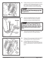
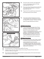
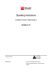
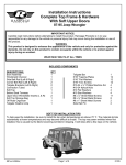
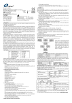
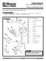
HARDTOP WIRING KIT 2000 2001 JEEP WRANGLER (TJ) INSTALLATION INSTRUCTIONS Read entire instructions thoroughly before starting. References to the service manual wiring diagrams and operation sections will be required for adjustments, fastener torques, and troubleshooting. TOOLS REQUIRED: • A selection of phillips head screwdrivers • 15mm socket • 10mm socket • Solder • Electrical tape • A selection of flat head screwdrivers 10 CONTENTS: Item Qty. 9 ** 1 11 12 8 6 7 5 • Modeler’s knife Description 1 1 Hardtop Wiring Assembly 2 12 Tie Straps 3 1 Grommet 4 1 Rear Window Washer Pump 5 1 Reservoir 6 2 Maxi Fuses 7 1 HBL Relay 8 1 Mini Fuse 9 1 Red 10-way Connector 10 1 Yellow Locking Wedge 11 1 HBL Switch 12 1 Rear Wipe Switch 13 1 Instruction Sheet 2 3 4 * NOTE: This harness carries the same colors and wire functions as the O.E. harness. K 6 8 5 8 3 7 3 11/21/00 Page 1 of 6 Rear Washer Supply Hose 10-way Connector Driver’s Side Center Sport Bar 1) Find existing 10-way connector and rear washer supply hose located at the driver’s side rear hardtop pillar. Plug and lock the corresponding connections from the hardtop overlay harness (Item 1). 2) Route harness forward and tuck in-between the existing harness and the body sheet metal. 3) Carefully remove wire harness protector panel from the back of the driver’s center sport bar. 4) Route hardtop overlay harness down and inbetween the sport bar and body sheet metal. 5) Using tie straps (Item 2), secure overlay harness to the existing body harness. 6) Re-install the wire harness protector panel. 7) Continue routing overlay harness forward and under the driver’s door sill. 8) Locate unused round grommet directly below the main bulkhead wiring grommet and remove it by pushing in from the engine compartment side. Discard the grommet. 9) Route ground eyelet and washer reservoir connections from the overlay harness forward thru the bulkhead and seat the in-line grommet. In-Line Grommet Clutch Pedal K 6 8 5 8 3 7 3 11/21/00 Page 2 of 6 Ground Eyelet New Reservoir Rear Window Washer Pump Windshield Washer Pump 10) Disconnect negative battery cable and isolate. 11) Using a 15mm socket, install ground eyelet from the overlay harness to existing ground located on the driver’s side of the upper bulkhead. 12) Using a 10mm socket, unscrew three bolts to remove the existing windshield washer reservoir. 13) Remove and retain the lid, windshield washer pump, grommet and fluid. Discard the reservoir. 14) Sub-assemble the supplied grommet (Item 3) and rear window washer pump (Item 4) to the new reservoir (Item 5). 15) Sub-assemble the retained grommet, windshield washer pump, lid, and fluid to the new reservoir. 16) Using three existing bolts, install new reservoir assembly to the vehicle. 17) Plug-in 2-way connector and supply hose from the overlay harness to the corresponding connections on the rear window washer pump. 18) Re-install existing 2-way connector and supply hose to the windshield washer pump. 19) Using tie straps, secure overlay harness to the existing engine harness. 2-way Connector Rear Window Washer Supply Hose K 6 8 5 8 3 7 3 11/21/00 Page 3 of 6 I/P Top Cover 20) Remove cover from the power distribution center. (Fuse and relay locations are shown on the cover). 21) Install one of the maxi fuses (Item 6) to the HBL fuse location of the PDC. 22) Install HBL relay (Item 7) to the HBL location of the PDC. 23) Install mini fuse (Item 8) to cavity #17 of the fuse panel (located behind the glove box). NOTE: Most vehicles will have a mini fuse already installed. If so, disregard step #23. I/P Center Bezel 24) Pry-up to remove the I/P top cover. 25) Remove ash receiver and unscrew three phillips head screws to remove the I/P center bezel. 26) Unscrew four phillips head screws from the cigar lighter/switch plate. Pull out and let hang. 27) Unscrew four phillips head screws from the HVAC control unit. Pull out and let hang. 28) Unscrew five phillips head screws to remove the I/P cluster bezel. 29) Unscrew four phillips head screws to remove the I/P cluster. 30) Unscrew four phillips head screws to remove the knee blocker trim panel and knee blocker. HVAC Control Unit Cigar Lighter/ Switch Plate I/P Cluster I/P Cluster Bezel K 6 8 5 8 3 7 3 11/21/00 Page 4 of 6 31) 100-way Connector Find the 100-way connector located under the I/P and bolted to the LH body panel support. Un-plug red 10-way connector from the bottom cavity. Remove the connector’s yellow locking wedge. NOTE: If there is no existing 10-way connector to be found, use the connector (Item 9) and locking wedge (Item 10) supplied in kit. Red 10-way Connector 32) Brown/Pink Cavity #4 Yellow Cavity #3 Red 10-way Connector Insert four terminaled wires from the overlay harness into either the existing or supplied connector as shown in the illustration at left. NOTE: Some models will have existing pink/white and yellow wires in the 10-way connector. The corresponding wires from the overlay harness must be center spliced onto these existing wires. Solder the splices and wrap with electrical tape to prevent shorts. Pink/White Cavity #2 33) Install yellow locking wedge and plug the 10-way connector back into the 100-way connector. 34) Find grey 10-way connector located under the I/P and near the top of the 100-way connector. 35) Cut Blue/White wire free off the 10-way connector. Splice this wire to the Blue/White wire from the overlay harness. Solder and insulate the splice. Black/White Cavity #1 Grey 10-way Connector Blue/White Wire K 6 8 5 8 3 7 3 11/21/00 Page 5 of 6 Rear Wipe Switch Overlay Harness Connectors 36) Route two switch connectors and Orange wire from the overlay harness inside of I/P to the switch plate and HVAC unit. 37) Remove two block-off plugs from the switch plate and install the HBL switch (Item 11) and rear wipe switch (Item 12). 38) Plug and lock 6-way and 4-way connectors from the overlay harness into the switches. 39) Center splice and tape Orange wire from the overlay harness to tan wire (located in cavity #4 of 5-way HVAC connector.) This wire controls the lights in the wiper and defroster switches. HBL Switch HVAC Control Unit 2000 Model Year Vehicle: Orange Wire 5-Way Connector 2000 Model Year Vehicle 41a) Remove the right (passenger’s side) 10-way connector from back of the I/P cluster housing. (Squeeze in on tabs and slide connector off). Remove 3" of tape wrap back from the connector. Disengage locking wedge by pulling it partially out. Insert Dk. Blue/Lt. Green and Lt. Blue/White (large terminaled) wires from the overlay harness into the 10-way connector as shown. Trim and tape back the unused wires. 2001 Model Year Vehicle: Dk. Blue/Lt. Green Cavity #4 Lt. Blue/White Cavity #3 41b) Remove the left (driver’s side) 16-way connector from back of the I/P cluster housing. Remove 3" of tape wrap back from the connector. Disengage locking wedge by pulling it partially out. Insert Dk. Blue/Lt. Green wire into cavity #1. Insert Lt. Blue/White wire into cavity #7. Trim and tape back the unused wires. 42) Re-install connector to I/P bracket and re-install the I/P cluster. 43) Using tie straps, secure the overlay harness to the existing I/P harness. Be sure there is no interference with any moving parts. 44) Re-connect the negative battery cable and check for proper operation of the rear window wiper/ washer, defroster, and dome lamp. K 6 8 5 8 3 7 3 11/21/00 Page 6 of 6