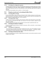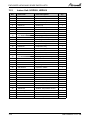
1
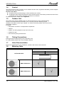
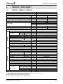
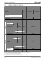
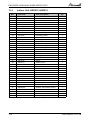
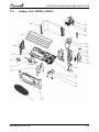
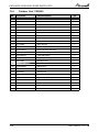
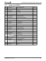
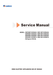
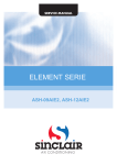
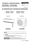
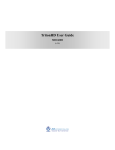
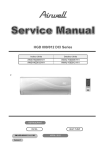
Indoor Units
Outdoor Units
AWSI-HDD009-H11
AWSI-HED009-H11
AWAU-YDD009-H11
AWSI-HDD012-H11
AWSI-HED012-H11
AWAU-YDD012-H11
REFRIGERANT
R410A
SM HDDHED 1-A.1 GB
Version: 1
HEAT PUMP
NOVEMBER – 2010
LIST OF EFFECTIVE PAGES
LIST OF EFFECTIVE PAGES
Note: Changes in the pages are indicated by a “Revision#” in the footer of each effected page
(when none indicates no changes in the relevant page). All pages in the following list represent
effected/ non effected pages divided by chapters.
Dates of issue for original and changed pages are:
Original ....... 0 ........ August 2009
Total number of pages in this publication is 111 consisting of the following:
Page
No.
Revision
No. #
Page
No.
Revision
No. #
Page
No.
Revision
No. #
Title ....................... 1
A ........................... 1
i ............................. 1
1-1 - 1-3 ................ 1
2-1 - 2-5 ................ 1
3-1 ........................ 1
4-1 - 4-2 ................ 1
5-1 - 5-25 .............. 1
6-1 - 6-4 ................ 1
7-1 ........................ 1
8-1 ........................ 1
9-1 - 9-2 ................ 1
10-1 ...................... 1
11-1-11-21............. 1
12-1-12-7 .............. 1
13-1-13-10 ............ 1
14.......................... 1
15.......................... 1
Appendix -A ...........1
•
Zero in this column indicates an original page.
*Due to constant improvements please note that the data on this service manual can be modified with out notice.
**Photos are not contractual
A
SM HDDHED 1-A.1 GB
TABLE OF CONTENTS
Table of Contents
1.
INTRODUCTION ...................................................................................................1-1
2.
PRODUCT DATA SHEET ......................................................................................2-1
3.
RATING CONDITIONS ..........................................................................................3-1
4.
OUTLINE DIMENSIONS .......................................................................................4-1
5.
PERFORMANCE DATA & PRESSURE CURVES ...............................................5-1
6.
SOUND LEVEL CHARACTERISTICS ..................................................................6-1
7.
ELECTRICAL DATA ..............................................................................................7-1
8.
WIRING DIAGRAMS .............................................................................................8-1
9.
REFRIGERATION DIAGRAMS .............................................................................9-1
10. TUBING CONNECTIONS......................................................................................10-1
11.
CONTROL SYSTEM .............................................................................................11-1
12. TROUBLESHOOTING ..........................................................................................12-1
13. EXPLODED VIEWS AND SPARE PARTS LISTS .................................................13-1
14. APPENDIX A .........................................................................................................14-1
SM HDDHED 1-A.1 GB
i
INTRODUCTION
1.
INTRODUCTION
1.1
General
HDD/HED series is a monosplit DCI inverter air conditioner designed for residential buildings.
The ODU YDD009/012 product is a DC inverter outdoor with high technology. By using DC compressor
sine wave torque control technology, this product provides more comfort and economical operating.
The IDU HDD/HED-009/012 is a high-wall mounted type indoor with modern apperance.
1.2
Main Features
The unit benefits from the most advanced technological innovations, namely:
• DC inverter technology.
• R410A models.
• Microprocessor control and indoor LED display.
• High COP,Energy efficiency class A in cooling/heating mode.
• Torque control for compressor running in lower Freqency but with low vibration and little sound.
• Max allowing tubing distance of 15m.
• Up to 5 m vertical high between indoor and outdoor units.
• Cooling operation at outdoor temperature up to 48ºC.
• Heating operation at outdoor temperature down to -15ºC.
• Easy installation and service.
• Sleep mode from remote control to save energy.
• ON/OFF timer and clock display.
• Vertical auto swing with motorized flap (any position stop).
• Intelligent Deicing.
• Memory from power failure.
• Rapid cooling/heating.
• I-Feel function.
• Cold air prevention in heating.
• Clean function (Blow dry).
• Self diagnosic (Error indications) for ease of maintenance.
1.3
Indoor Unit
The indoor unit is wall mounted, and can be easily fitted to many types of residential locations. It includes:
• LED display
• Variable speed with PG motor
• Motorized flap
• High efficiency filtration to ensure a best Air Quality : Advanced filtering combine
mechanical, Photo-catalytic + Bi-anti bacterial and observe bad gaseous and smokes.
SM HDDHED 1-A.1 GB
1-1
INTRODUCTION
1.4
Control
The microprocessor indoor controller, and an infrared remote control, supplied as standard, provide complete
operating function and programming.
Remote control RC 8:
► Compact and economically design, it offers excellent user comfort.
► Combining modern design with high technology, the RC8 remote control offers powerful functions of real
considering of user comfort and energy saving of air-conditioner.
For detail of functions, please refer to Appendix
1.5
Outdoor Unit
The outdoor units can be installed as floor or wall mounted units by using a wall supporting
bracket. The metal sheets are protected by anti- corrosion paint work allowing long life
resistance. All outdoor units are pre-charged. For further information please refer to the Product
Data Sheet, Chapter 2.
It includes :
• Compressor mounted in a soundproofed compartment :
• Axial fan.
• Outdoor coil with hydrophilic louver fins for RC units.
• Outlet air fan grill.
• Interconnecting wiring terminal block.
1.6
Tubing Connections
Flare type interconnecting tubing to be produced on site.
For further details please refer to the Installation Manual.
1.7
Inbox Documentation
Each unit is supplied with its own installation, operation and remote control manuals.
1.8
Matching Table
INDOOR UNITS
OUTDOOR UNITS
AWAU-YDD009-H11
AWAU-YDD012-H11
1-2
AWSI-HDD009-H11
AWSI-HDD012-H11
AWSI-HED009-H11
AWSI-HED012-H11
√
√
SM HDDHED 1-A.1 GB
PRODUCT DATA SHEET
2.
PRODUCT DATA SHEET
2.1
HDD009 / HED009 // YDD 009
HDD/HED009
YDD 009
Model Indoor Unit
Model Outdoor Unit
Installation Method of Pipe
Characteristics
Capacity (4)
Power input (4)
EER (Cooling) or COP(Heating) (4)
Energy efficiency class
Flared
Units
kW
kW
W/W
V
Ph
Hz
A
Power supply
Rated current
Power factor
Prated (IDU+ODU)
Circuit breaker rating
Fan type & quantity
Fan speeds
W
A
Cooling
Heating
SH/H/M/L
SH/H/M/L
SH/H/M/L
Min
SH/H/M/L
SH/H/M/L
OUTDOOR
INDOOR
Air flow (1)
External static pressure
Sound power level (2)
Sound pressure level (3)
Moisture removal
Condensate drain tube I.D
Dimensions
WxHxD
Net Weight
Package dimensions
WxHxD
Packaged weight
Refrigerant control
Compressor type, model
Fan type & quantity
Fan speeds
H
Air flow
H
Sound power level
H
H
Sound pressure level (3)
Dimensions
WxHxD
Net Weight
Package dimensions
WxHxD
Packaged weight
Refrigerant type
Standard charge
Additional charge
Liquid line
Suction line
Connections
between units
Max.tubing length
Max.height difference
Operation control type
(1)
(2)
(3)
(4)
RPM
RPM
m3/hr
Pa
dB(A)
dB(A)
l/hr
mm
mm
kg
mm
kg
RPM
m3/hr
dB(A)
dB(A)
mm
kg
mm
kg
kg(5m)
In.(mm)
In.(mm)
m.
m.
Cooling
0.45-3.23))2.65
0.2-1.35))0.8
3.30
A
Heating
0.45-4.1))3.52
0.2-1.45))0.95
3.70
A
220-240
1
50
6.3
0.97
6.8
0.97
1550
16A
Crossflow x 1
1300/1100/900/700
1300/1140/980/820
630/520/370/280
0
51/46/40/34
41/36/30/24
0.8
16
770x283x201
8
844x342x261
11
Capillary
Rotary,Daikin 1YC23AEXD
Propeller(direct) x 1
930
1600
57
47
658x550x275
28
771x592x348
32
R410A
0.74
15g/m(5m<L<15m)
1/4"(6.35)
3/8"(9.53)
Max. 15
Max. 5
Remote control
Rating conditions in accordance with ISO 5151 and ISO 13253 (for ducted units) and EN 14511.
Airflow in ducted units; at nominal external static pressure.
Sound power in ducted units is measured at air discharge.
Sound pressure level measured at 1 meter distance from unit.
SM HDDHED 1-A.1 GB
2-1
PRODUCT DATA SHEET
2.2
HDD012 / HED012 // YDD 012
HDD/HED012
YDD 012
Model Indoor Unit
Model Outdoor Unit
Installation Method of Pipe
Characteristics
Capacity (4)
Power input (4)
EER (Cooling) or COP(Heating) (4)
Energy efficiency class
Flared
Units
kW
kW
W/W
V
Ph
Hz
A
Power supply
Rated current
Power factor
Prated (IDU+ODU)
Starting current
Circuit breaker rating
Fan type & quantity
Fan speeds
W
A
A
Cooling
Heating
SH/H/M/L
SH/H/M/L
SH/H/M/L
Min
SH/H/M/L
SH/H/M/L
OUTDOOR
INDOOR
Air flow (1)
External static pressure
Sound power level (2)
Sound pressure level (3)
Moisture removal
Condensate drain tube I.D
Dimensions
WxHxD
Net Weight
Package dimensions
WxHxD
Packaged weight
Refrigerant control
Compressor type, model
Fan type & quantity
Fan speeds
H
Air flow
H
Sound power level
H
Sound pressure level (3)
H
Dimensions
WxHxD
Net Weight
Package dimensions
WxHxD
Packaged weight
Refrigerant type
Standard charge
Additional charge
Liquid line
Suction line
Connections
between units
Max.tubing length
Max.height difference
Operation control type
(1)
(2)
(3)
(4)
RPM
RPM
m3/hr
Pa
dB(A)
dB(A)
l/hr
mm
mm
kg
mm
kg
RPM
m3/hr
dB(A)
dB(A)
mm
kg
mm
kg
kg(5m)
In.(mm)
In.(mm)
m.
m.
Cooling
3.53(0.6-3.96)
1.1(0.22-1.45)
3.21
A
Heating
4.1(0.6-5.13)
1.14(0.22-1.55)
3.61
A
220-240
1
50
6.5
0.97
7.8
0.97
1650
16
Crossflow x 1
1350/1150/950/750
1350/1190/1020/850
680/560/410/330
0
52/47/41/35
42/37/31/25
1.5
16
770x283x201
9
844x342x261
12
Capillary
Rotary,Daikin 1YC23AEXD
Propeller(direct) x 1
930
1600
58
48
658x550x275
30
771x592x348
34
R410A
1
15g/m(5m<L<15m)
1/4"(6.35)
3/8"(9.53)
Max. 15
Max. 5
Remote control
Rating conditions in accordance with ISO 5151 and ISO 13253 (for ducted units) and EN 14511.
Airflow in ducted units; at nominal external static pressure.
Sound power in ducted units is measured at air discharge.
Sound pressure level measured at 1 meter distance from unit.
2-2
SM HDDHED 1-A.1 GB
RATING CONDITIONS
3.
RATING CONDITIONS
Rating conditions in accordance with ISO 5151 and ISO 13253 (for ducted units).
Cooling:
Indoor:
27oC DB 19oC WB
Outdoor: 35 oC DB
Heating:
Indoor:
20oC DB
Outdoor: 7oC DB 6oC WB
3.1
Operating Limits
3.1.1
R410A
Indoor
Cooling
Heating
Upper limit
32oC DB 23oC WB
46oC DB
Lower limit
21oC DB 15oC WB
10oC DB
Upper limit
27oC DB
24oC DB 18oC WB
Lower limit
10oC DB
-15oC DB -16oC WB
Voltage
SM HDDHED 1-A.1 GB
Outdoor
1-PH 50Hz / 198 – 264 V
3-1
OUTLINE DIMENSIONS
4.
OUTLINE DIMENSIONS
4.1
Indoor Unit: HDD009, HDD012, HED009, HED012
4.2
Outdoor Units: YDD009, YDD012
SM HDDHED 1-A.1 GB
4-1
PERFORMANCE DATA & PRESSURE CURVES
5.
PERFORMANCE DATA
5.1
HDD009, HED009
5.1.1
Cooling Capacity (kW) – Run Mode
230[V] : Indoor Fan at High Speed.
OD COIL
ENTERING AIR DB
TEMPERATURE
[oC]
ID COIL ENTERING AIR DB/WB TEMPERATURE [oC]
DATA
TC
SC
PI
TC
SC
PI
TC
SC
PI
TC
SC
PI
TC
SC
PI
TC
SC
PI
-10 - 20
(protection range)
25
30
35
40
46
22/15
24/17
27/19
29/21
32/23
2.46
1.74
0.63
2.34
1.70
0.70
2.22
1.66
0.78
2.10
1.61
0.85
1.96
1.56
0.94
80 - 110 % of nominal
80 - 105 % of nominal
25 - 50 % of nominal
2.62
2.78
2.94
1.78
1.82
1.85
0.64
0.65
0.66
2.50
2.66
2.82
1.74
1.77
1.81
0.73
0.71
0.74
2.38
2.70
2.54
1.69
1.73
1.76
0.80
0.79
0.81
2.26
2.58
2.42
1.65
1.68
1.72
0.86
0.87
0.89
2.12
2.28
2.44
1.59
1.63
1.67
0.95
0.96
0.97
3.10
1.89
0.68
2.98
1.84
0.75
2.86
1.80
0.82
2.74
1.75
0.90
2.60
1.70
0.99
LEGEND
TC
SC
PI
WB
DB
ID
OD
5.1.2
–
–
–
–
–
–
–
Total Cooling Capacity, kW
Sensible Capacity, kW
Power Input, kW
Wet Bulb Temp., (oC)
Dry Bulb Temp., (oC)
Indoor
Outdoor
Capacity Correction Factors
Cooling Capacity Ratio Vs. Outdoor Temperature
1.20
Capacity Ratio
1.10
1.00
0.90
0.80
0.70
0.60
0.50
20
25
30
35
40
45
Outdoor Temperature [deg C]
SM HDDHED 1-A.1 GB
5-1
PERFORMANCE DATA & PRESSURE CURVES
5.1.3
Heating Capacity (kW) - Run Mode
230[V] : Indoor Fan at High Speed.
ID COIL ENTERING AIR DB TEMPERATURE [oC]
OD COIL
ENTERING
AIR DB/WB
TEMPERATURE
[oC]
DATA
TC
PI
TC
PI
TC
PI
TC
PI
TC
PI
TC
PI
TC
PI
TC
PI
-15/-16
-10/-12
-7/-8
-1/-2
2/1
7/6
10/9
15/12
15
20
25
2.20
0.58
2.45
0.70
2.64
0.79
2.73
0.83
2.79
0.86
3.61
0.91
3.81
0.96
4.01
1.02
2.05
0.64
2.30
0.76
2.48
0.85
2.58
0.89
2.64
0.92
3.46
0.97
3.66
1.02
3.86
1.08
1.89
0.70
2.14
0.82
2.33
0.91
2.42
0.95
2.49
0.98
3.31
1.03
3.51
1.08
3.70
1.13
15-24
TC
85 - 105 % of nominal
(Protection Range)
PI
80 - 120 % of nominal
LEGEND
TC
PI
WB
DB
ID
OU
5.1.4
–
–
–
–
–
–
Total Heating Capacity, kW
Power Input, kW
Wet Bulb Temp., (oC)
Dry Bulb Temp., (oC)
Indoor
Outdoor
Capacity Correction Factors
Heating Capacity Ratio Vs. Outdoor Temperature
Capacity Ration
1.20
1.10
1.00
0.90
0.80
0.70
0.60
0.50
-15
-10
-5
0
5
10
15
Outdoor WB Temperature [deg C]
5-2
SM HDDHED 1-A.1 GB
PERFORMANCE DATA & PRESSURE CURVES
5.1.5
Model: HDD009, HED009
5.1.5.1
Cooling
Suction Pressure [kPa]
1400
Indoor
DB/WB
1300
1200
22/15
1100
24/17
1000
900
27/19
29/21
800
32/23
700
600
500
10
15
20
25
30
35
40
45
Outdoor DB Temperature
6.00
Input Current [A]
5.50
5.00
22/15
4.50
24/17
4.00
27/19
3.50
29/21
3.00
32/23
2.50
2.00
10
15
20
25
30
35
40
45
Outdoor DB Temperature
SM HDDHED 1-A.1 GB
5-3
PERFORMANCE DATA & PRESSURE CURVES
Discharge Pressure [kPa]
5.1.5.2
Heating
4000
3750
3500
3250
3000
2750
2500
2250
2000
1750
1500
Indoor DB
15
20
25
-15
-10
-5
0
5
10
15
Outdoor WB Temperature
7.00
Input Current [A]
6.50
6.00
Indoor DB
5.50
15
5.00
20
4.50
25
4.00
3.50
3.00
-15
-10
-5
0
5
10
15
Outdoor WB Temperature
5-4
SM HDDHED 1-A.1 GB
PERFORMANCE DATA & PRESSURE CURVES
5.2
HDD012, HED012
5.2.1
Cooling Capacity (kW) - Run Mode
230[V] : Indoor Fan at High Speed.
ID COIL ENTERING AIR DB/WB TEMPERATURE [oC]
OD COIL
ENTERING AIR DB
TEMPERATURE [oC]
DATA
TC
SC
PI
TC
SC
PI
TC
SC
PI
TC
SC
PI
TC
SC
PI
TC
SC
PI
-10 - 20
(protection range)
25
30
35
40
46
22/15
24/17
27/19
29/21
32/23
80 - 110 % of nominal
80 - 105 % of nominal
25 - 50 % of nominal
3.33
2.37
0.90
3.17
2.31
1.00
3.01
2.25
1.11
2.85
2.19
1.21
2.66
2.12
1.34
3.55
2.42
0.91
3.39
2.36
1.02
3.23
2.30
1.12
3.07
2.24
1.23
2.88
2.17
1.35
3.77
2.46
0.93
3.61
2.41
1.04
3.45
2.35
1.14
3.29
2.29
1.24
3.10
2.21
1.37
3.99
2.51
0.95
3.83
2.45
1.05
3.67
2.39
1.16
3.51
2.33
1.26
3.31
2.26
1.39
4.21
2.56
0.96
4.05
2.50
1.07
3.88
2.44
1.17
3.72
2.38
1.28
3.53
2.31
1.40
LEGEND
TC
SC
PI
WB
DB
ID
OD
5.2.2
–
–
–
–
–
–
–
Total Cooling Capacity, kW
Sensible Capacity, kW
Power Input, kW
Wet Bulb Temp., (oC)
Dry Bulb Temp., (oC)
Indoor
Outdoor
Capacity Correction Factors
Heating Capacity Ratio Vs. Outdoor Temperature
Capacity Ration
1.20
1.10
1.00
0.90
0.80
0.70
0.60
0.50
-15
-10
-5
0
5
10
15
Outdoor WB Temperature [deg C]
SM HDDHED 1-A.1 GB
5-5
PERFORMANCE DATA & PRESSURE CURVES
5.2.3
Heating Capacity (kW) - Run Mode
230[V] : Indoor Fan at High Speed.
ID COIL ENTERING AIR DB TEMPERATURE [oC]
OD COIL
ENTERING
AIR DB/WB
TEMPERATURE
[oC]
DATA
15-24
TC
PI
TC
PI
TC
PI
TC
PI
TC
PI
TC
PI
TC
PI
TC
PI
TC
(Protection Range)
PI
-15/-16
-10/-12
-7/-8
-1/-2
2/1
7/6
10/9
15/12
15
20
25
2.56
0.71
2.85
0.85
3.07
0.96
3.17
1.02
3.25
1.05
4.20
1.11
4.43
1.17
4.66
1.24
2.38
0.78
2.67
0.92
2.89
1.03
2.99
1.09
3.07
1.12
4.02
1.18
4.25
1.24
4.48
1.31
2.20
0.85
2.49
1.00
2.71
1.10
2.82
1.16
2.89
1.20
3.84
1.25
4.07
1.32
4.30
1.38
85 - 105 % of nominal
80 - 120 % of nominal
LEGEND
TC
PI
WB
DB
ID
OU
5.2.4
–
–
–
–
–
–
Total Heating Capacity, kW
Power Input, kW
Wet Bulb Temp., (oC)
Dry Bulb Temp., (oC)
Indoor
Outdoor
Capacity Correction Factors
Cooling Capacity Ratio Vs. Outdoor Temperature
1.20
Capacity Ratio
1.10
1.00
0.90
0.80
0.70
0.60
0.50
20
25
30
35
40
45
Outdoor Temperature [deg C]
5-6
SM HDDHED 1-A.1 GB
PERFORMANCE DATA & PRESSURE CURVES
5.2.5
Model: HDD012, HED012
5.2.5.1
Cooling
Suction Pressure [kPa]
1400
Indoor
DB/WB
1300
1200
22/15
1100
24/17
1000
900
27/19
29/21
800
32/23
700
600
500
10
15
20
25
30
35
40
45
Outdoor DB Temperature
6.00
Input Current [A]
5.50
5.00
22/15
4.50
24/17
4.00
27/19
3.50
29/21
3.00
32/23
2.50
2.00
10
15
20
25
30
35
40
45
Outdoor DB Temperature
SM HDDHED 1-A.1 GB
5-7
PERFORMANCE DATA & PRESSURE CURVES
5.2.5.2
Heating
Suction Pressure [kPa]
1400
Indoor
DB/WB
1300
1200
22/15
1100
24/17
1000
900
27/19
29/21
800
32/23
700
600
500
10
15
20
25
30
35
40
45
Outdoor DB Temperature
6.00
Input Current [A]
5.50
5.00
22/15
4.50
24/17
4.00
27/19
3.50
29/21
3.00
32/23
2.50
2.00
10
15
20
25
30
35
40
45
Outdoor DB Temperature
5-8
SM HDDHED 1-A.1 GB
SOUND LEVEL CHARACTERISTICS
6.
SOUND LEVEL CHARACTERISTICS
6.1
Sound Pressure Level
Figure 1. Wall Mounted
6.2
Sound Pressure Level Spectrum (Measured as Figure 1)
HDD012 / HED012
-70NC
-60NC
-50NC
-40NC
-30NC
APPROXIMATE
THRESHOLD OF
HEARING FOR
CONTINUOUS
NOISE
-20NC
Hz, BAND CENTER FREQUENCIES
SM HDDHED 1-A.1 GB
MICRO BAR0.002 dB re , OCTAVE BAND SOUND PRESSURE LEVEL
MICRO BAR0.002 dB re , OCTAVE BAND SOUND PRESSURE LEVEL
HDD009 / HED009
-70NC
-60NC
-50NC
-40NC
-30NC
APPROXIMATE
THRESHOLD OF
HEARING FOR
CONTINUOUS
NOISE
-20NC
Hz, BAND CENTER FREQUENCIES
6-1
SOUND LEVEL CHARACTERISTICS
6.3
Outdoor units
Fig.2
Microphone Distance from Unit
6.4
Sound Pressure Level Spectrum (Measured as Figure 2)
-70NC
-60NC
-50NC
-40NC
-30NC
APPROXIMATE
THRESHOLD OF
HEARING FOR
CONTINUOUS
NOISE
-20NC
Hz, BAND CENTER FREQUENCIES
6-2
YDD009/YDD012 Heating
MICRO BAR0.002 dB re , OCTAVE BAND SOUND PRESSURE LEVEL
MICRO BAR0.002 dB re , OCTAVE BAND SOUND PRESSURE LEVEL
YDD009/YDD012 Cooling
-70NC
-60NC
-50NC
-40NC
-30NC
APPROXIMATE
THRESHOLD OF
HEARING FOR
CONTINUOUS
NOISE
-20NC
Hz, BAND CENTER FREQUENCIES
SM HDDHED 1-A.1 GB
ELECTRICAL DATA
7.
ELECTRICAL DATA
7.1
Single Phase Units
MODEL
YDD009
YDD012
To indoor
1PH / 220-240V / 50Hz
Power Supply
Max Current, A
6.8
7.8
Circuit Breaker,A
Power Supply Wiring No. X Cross
Section mm2
Interconnecting Cable RC
Model No. X Cross Section mm2
16.0
16.0
3x1.5 mm2
3x1.5 mm2
4x1.5 mm2
4x1.5 mm2
NOTE
Power wiring cord should comply with local lows and electrical regulations requirements.
SM HDDHED 1-A.1 GB
7-1
WIRING DIAGRAMS
8.
WIRING DIAGRAMS
8.1
Indoor Units: HDD009, HDD012, HED009, HED012
8.2
Outdoor Units: YDD009, YDD012
SM HDDHED 1-A.1 GB
8-1
REFRIGERATION DIAGRAMS
9.
REFRIGERATION DIAGRAMS
9.1
HDD009 / HED009 // YDD009
9.2
HDD012 / HED012 // YDD012
SM HDDHED 1-A.1 GB
9-1
TUBING CONNECTIONS
10.
TUBING CONNECTIONS
TUBE (Inch)
¼”
⅜”
½”
⅝”
¾”
11-13
13-20
11-13
40-45
13-20
11-13
60-65
18-25
11-13
70-75
18-25
11-13
80-85
40-50
11-13
TORQUE (Nm)
Flare Nuts
Valve Cap
Service Port Cap
1.
2.
3.
4.
5.
6.
7.
8.
Valve Protection Cap-end
Refrigerant Valve Port (use Allen wrench to open/close)
Valve Protection Cap
Refrigerant Valve
Service Port Cap
Flare Nut
Unit Back Side
Copper Tube
When the outdoor unit is installed above the indoor unit an oil trap is required every 5m along the
When
theline
outdoor
is installed
unit an oil trap is required every 5m along the suction
.
suction
at theunit
lowest
point above
of the the
riserindoor
line
at
the
lowest
point
of
the
riser.
Incase
the
indoor
unit is no
installed
the outdoor, no trap is
In case the indoor unit is installed above the outdoor,
trap isabove
required.
required.
SM HDDHED 1-A.1 GB
10-1
CONTROL SYSTEM
11
CONTROL SYSTEM
11.1
Electronic Control
11.1.1
Abbreviations
Abbreviation
A/C
BMS
PWR
CTT
DCI
EEV
HE
HMI
HST
Hz
ICT
IDU
MCU
OAT
OCT
ODU
OFAN
PFC
RAC
RAT
RC
RCT
RGT
RPS
RV
SB,STBY
SUCT
S/W
TBD
TMR
11.1.2
Definition
Air Condition
Building Management System
System Power
Compressor Top Temperature sensor
DC Inverter
Electronic Expansion Valve
Heating Element
Human Machine Interface
Heat Sink Temperature sensor
Hertz (1/sec) – electrical frequency
Indoor Coil Temperature (RT2) sensor
Indoor Unit
Micro Controller Unit
Outdoor Air Temperature sensor
ODU Coil Temperature sensor
Outdoor Unit
Outdoor Fan
Power Factor Corrector
Residential A/C
Room Air Temperature sensor
Reverse Cycle (Heat Pump)
Remote Control Temperature sensor
Return Gas Temperature sensor
Rounds per second (mechanical speed)
Reverse Valve
Stand By
Compressor Suction Temperature sensor
Software
To Be Defined
Timer
System Operation Concept
The control function is divided between indoor and outdoor unit controllers. Outdoor unit is the system
‘Master’, requesting the indoor unit for cooling/heating capacity supply. The indoor unit is the system
‘Slave’ and it must supply the required capacity unless it enters into a protection mode avoiding it
from supplying the requested capacity.
Target frequency is transferred via indoor to outdoor communication, and the caculation is based on
room temperature and set point temperature.
11.1.3
Compressor Frequency Control
The Compressor Frequency Control is based on the PI scheme.
When starting the compressor, or when conditions are varied due to the change of the room
condition, the frequency must be initialized according to the ΔD value of the indoor unit and the Q
value of the indoor unit.
Q value: Indoor unit output determined from indoor unit capacity, air flow rate and other factors.
1. P control
Calculate ΔD value in each sampling time (20 seconds), and adjust the frequency according to its
difference from the frequency previously calculated.
2. I control
If the operating frequency is not change more than a certain fixed time, adjust the frequency up
and down according to the ΔD value.
Obtaining the fixed ΔD value
SM HDDHED 1-A.1 GB
11-1
CONTROL SYSTEM
When the ΔD value is small- decrease the frequency
When the ΔD value is large- increase the frequency
3. Frequency management when other controls are functioning
When frequency is drooping;
Frequency management is carried out only when the frequency droops.
For limiting lower limit
Frequency management is carried out only when the frequency rises.
4. Maximum and minimum limits of frequency by PI control
The frequency upper and lower limits are set depending on indoor unit.
When low noise commands come from the indoor unit or when outdoor unit low noise or quiet
commands come from indoor unit, the upper limit frequency must be lowered than the usual
setting.
(see 11.1.3.1)
11.1.3.1 Frequancy range
The compressor frequency limitation is set by the following table
Minimum Frequency(MinFreq)
09
16
16
Mode
Cooling
Heating
Maximum Frequency(MaxFreq)
12
16
16
See following table
The maximum allowed frequency is extracted from the following:
Mode
Cooling
Heating
11.1.3.2
Night Mode
ON
OFF
ON
OFF
Maximum Frequency(MaxFreq)
09
78
78
90
98
12
92
92
95
108
Frequency Changes Control
Frequency change rate is 1 Hz/sec.
11.1.3.3
Compressor Starting Control
When turning the compressor from OFF to ON, the upper limit of frequency must be set as follows.
(The function must not be used when defrosting.)
11.1.3.4
Minimum On and Off Time
Prohibit to turn ON the compressor for 3 minutes after turning it off.(except during deicing
protection)
11-2
SM HDDHED 1-A.1 GB
CONTROL SYSTEM
11.1.4
Indoor Fan Control
8 Indoor fan speeds are determined for each model. 4 speeds for COOL modes and 4 speeds for
HEAT mode.
Unit Model
09
12
Mode
Turbo(Super high)
High
Medium
Low
Cooling
Heating
Cooling
Heating
1300
1300
1350
1350
1100
1140
1150
1190
900
980
950
1020
700
820
750
850
In high/ medium/ low indoor fan user setting, unit will operate fan in selected speed.
In AutoFan user setting, fan speed will be adjusted automatically according to the difference
between actual room temperature(RAT) and user set point temperature(SPT).
Indoor Fan speed
RAT-SPT
Cooling
Heating
High
Medium
Low
>=2
<=1
(0,2)
(1,3)
<=0
>=3
In DRY mode, the automatic fan speed is forced to be low.
11.1.4.1
Turbo Speed
In COOL and HEAT mode (not available in AUTO, DRY, FAN mode), press the Turbo button, the
super high fan speed is selected on Remote control and the indoor fan rotates at super high speed.
11.1.5
Outdoor Fan Control
11.1.5.1
OFAN Speed Type
The outdoor fan motor is a one speed AC motor and controllered by the relay on outdoor controller.
11.1.5.2
General rules
1. The outdoor fan is ON when compressor ON during cooling, dring and heating mode.
2. Outdoor fan OFF will delay 30sec when compressor is OFF during cooling and heating mode.
3. Outdoor fan control under outdoor deicing please refer to 11.11.5
11.1.6
Refrigerant control
Capiliary is used in model 09 and 12
11.1.7
Reversing Valve (RV) Control
Reversing valve is on in heat mode.
Switching of RV state is done only after compressor is off for over 2 minutes.
11.2
Fan Mode
In this mode, the indoor fan may run at high,medium,low and automatic speed. The compressor,
outdoor fan and 4-way valve will be OFF.
In this mode, the range of setting temperature is 16~30 oC
11.3
Cool Mode
If RAT≥SPT, the unit starts cooling operation. In this case, the compressor and outdoor fan will
operate and the indoor fan will run at the setting speed.
If RAT≤SPT-2, the compressor will stop operation and the outdoor fan will delay 30 seconds to
stop. While the indoor fan will run at the setting speed.
If SPT-2<RAT<SPT, the unit will maintain the previous status.
SM HDDHED 1-A.1 GB
11-3
CONTROL SYSTEM
RAT
SPT
SPT-2
>=6min
COMP
ON
OFAN
ON
IFAN
ON
11.3.1
>=3min
OFF
30s
>=6min
ON
OFF
OFF
ON
OFF
30s
Indoor Fan operation under Cool Mode
When SPT-RAT<0, if indoor fan motor operates at high speed, the fan motor will operate at medium
speed. The medium speed or low speed will be maintained; (this condition should be executed when
compressor starts up); this function will be excluded in the super high speed; When (RAT-SPT) ≥1 ,
the fan will return to the setting fan speed.
In AutoFan user setting, fan speed will be adjusted automatically according to the SPT and RAT,
rerfer to 11.1.4
11.4
Heat Mode
If RAT<SPT+1.5 AND for certain peiod, the unit will operate in heating mode. The compressor,
outdoor fan and 4-way valve will operate and the indoor fan will delay 3min to start at the latest
If RAT≥SPT+1.5, the compressor will stop, the outdoor fan will delay 30s to stop and the indoor fan
will blow for 60s at setting speed. During this period, the fan speed can’t be switched.
RAT
*1
SPT+1.5
>=6min
COMP
ON
OFAN
ON
>=3min
OFF
30s
OFF
>=6min
ON
OFF
ON
30s
OFF
Anti-cold function
Max 3 min
IFAN
RV
Set Speed
60s
Set Speed
60s
ON
Remark: *1 – accumulated time of RAT<SPT+1.5
11.4.1
Indoor Fan Control in Heat Mode
Indoor fan speed depends on the indoor coil temperature
Anti-cold air function
When starting the heating mode, anti-cold air function will be activated and indoor fan can run at low
speed or stop running. This function will terminate after the unit runs for 3min or the ICT reaches 42
degree.
Residual heat blowing function
During heating, when the stopping condition for the compressor is reached, the compressor and the
outdoor fan motor stop running while the louver moves to position L. The indoor fan will stop after
running for 60s at setting speed.
11-4
SM HDDHED 1-A.1 GB
CONTROL SYSTEM
11.5
Auto Cool/Heat Mode
In AUTO mode, the system selects the running mode (COOL/HEAT/FAN) automatically according
to the room temperature. The display shows the actual running mode and setting temperature.
There will be 30s delay for mode conversion.
1. When RAT≥25 oC, the cooling mode is selected.
2. When RAT≤22 oC, the unit runs in heating mode
3. When 22 oC <RAT< 25 oC, upon initial startup, the unit will enter auto mode and run in
automatic fan mode. If the other mode changes into auto mode, the previous running mode will
remain.
11.6
Dry Mode
If RAT>SPT, the unit starts drying operation. Indoor fan, outdoor fan and compressor will operate and
the indoor fan will run at low speed.
If SPT-2≤RAT≤SPT, the unit will keep running in the original mode.
If RAT<SPT-2, the compressor will stop running and the outdoor fan will delay 30 seconds to stop.
While the indoor fan will run at low speed.
In this mode, the Reverse Valve will be OFF and the temperature setting range is 16~30.
RAT
SPT
SPT-2
>=6min
COMP
ON
OFAN
ON
IFAN
11.7
>=3min
OFF
30s
OFF
>=6min
ON
ON
OFF
30s
OFF
ON(Low fan speed)
Louver Control
After power on, the up and down swing louver will automatically open and
then close completely.
In heating mode, if the swing function is not set, the up and down louver will
rotate to maximum in clockwise direction. Then it will rotate to position D.
Under other states, the upper and lower air deflector will rotate to level L.
If the swing function is set when starting the unit, the louver will swing between
Position L and D. there are 7 states for louver: in position L, A, B, C, D, and
swing between L and D, stop in any place between Position L and position D.
When the unit is turned off, the air deflector will stay in position 0.
The swing is available only when the swing function is set and the indoor fan is running.
The louver swing can also be set between L and B, between A and C, between B and D.
11.8
Clean function
Clean function enables dring the indoor coil after Cool or Dry mode to avoid mould.
will be shown on remote control.
Press CLEAN button in Cool or Dry mode, and the
Under clean function, the indoor fan will continue operation for 10 min at low speed after the unit is
turned OFF.
SM HDDHED 1-A.1 GB
11-5
CONTROL SYSTEM
Clean function is defaulted as OFF after unit is Power ON.
Clean function is not available in Auto, Fan or Heat mode.
11.9
Sleep function
Pressing SLEEP button will enable the Sleep function.
Sleep function in Cool and Dry mode:
The SPT will be adjusted according to following chart.
will be shown on remote control.
SPT+3
SPT+2
SPT+1
SPT
1hr
1hr
1hr
Sleep function in Heat mode:
The SPT will be adjusted according to following chart.
SPT
SPT-1
SPT-2
SPT-3
1hr
1hr
1hr
Press either Sleep button or ON/OFF button can cancel the Sleep function.
Sleep function will not be available in Auto mode or Fan mode.
11.10
I-Feel function
I-Feel function maintains the room temperature by comparing the RCT on remote control.
will be shown on remote control.
Pressing IFEEL button will enable the I-Feel function.
Under I-Feel funtion, remote control sends I-Feel data every 10 min to IDU controller. If the IDU
controller does not received I-Feel data after 11 min. I-Feel function will be interrupted and then the
AC will work according to RAT on the IDU.
I-Feel function can not be remembered after power failure.
11.11
Protections
There are 4 protection codes.
Normal (Norm) – unit operate normally.
Stop Rise (SR) – compressor frequency can not be raised but does not have to be decreased.
HzDown – Compressor frequency is reduced by 2Hz/s (For 9k/12k, temperature protection is
4Hz/60s)
Stop Compressor (SC) – Compressor is stopped.
11-6
SM HDDHED 1-A.1 GB
CONTROL SYSTEM
11.11.1
Indoor Coil Defrost Protection
Conditions for Start Controlling
Judge the controlling start with the ICT (Indoor Coil Temperature) after 2 sec from operation start.
During cooling operation, the signals being sent from the indoor unit allow the operating frequency
limitation and then prevent freezing of the indoor heat exchanger.
Compressor will stop when ICT <= -1 oC for continuous 3 mins.
If the unit stops as such protection for 6 times, it can not resume running automatically and display
malfunction, it can resume by pressing ON/OFF.
11.11.2
Indoor Coil over Heating Protection
Conditions for Start Controlling
Judge the controlling start with the ICT after 2 sec from operation start.
During heating operation, the signals being sent from the indoor unit allow the operating frequency
limitation and prevent abnormal high pressure.
Compressor will stop when ICT reaches 65 oC
If the unit stops as such protection for 6 times, it can not resume running automatically and display
malfunction, it can resume by pressing ON/OFF.
11.11.3
Compressor over Heating Protection
The Discharging temperature is used as the compressor’s internal temperature. If the discharge
temperature rises above a certain level, the operating frequency upper limit is set to keep this
temperature from going up further.
Compressor will stop when CTT reaches certain value(see folowing table)
Compressor frequency(Hz)
CTT temperature (Stop compressor)
>50
[39,50]
<39
110 oC
105 oC
100 oC
If the unit stops as such protection for 6 times, it can not resume running automatically and display
malfunction, it can resume by pressing ON/OFF.
11.11.4
Compressor over Current Protection
Detect an input current by the CT during the compressor is running, and set the frequency upper
limit from such input current. In case of heat pump model, this control is the upper limit control
function of the frequency which takes priority of the lower limit of four way valve activating
compensation.
Detail
Compressor will stop when AC current reaches 14.0A for continuesly 2.5s.
If the unit stops as such protection for 6 times, it can not resume running automatically and display
malfunction, it can resume by pressing ON/OFF.
SM HDDHED 1-A.1 GB
11-7
CONTROL SYSTEM
11.11.5
Outdoor Coil Deicing Protection
This protection is for Heat Pump Only
This protection is carried out by the cooling cycle (reverse cycle). The defrosting time or outdoor
heat exchanger temperature must be more than its setting values when finishing the deicing
protection.
In the deicing protection, IFAN is forced OFF.
11.11.5.1
Deicing Starting Conditions
The starting conditions must be made with the outdoor air temperature (OAT) and outdoor coil
temperature (OCT). Under the conditions that the system is in heating operation, 6 minutes after
the compressor is started and more than 44 minutes of accumulated time pass since the start of
the operation or ending the defrosting.
Deicing interval time is changed as a function of deicing time. If deicing time is shorter than former
deicing time, the deicing interval time will be increased. If deicing time is longer than former deicing
time, the deicing interval time will be decreased.
11.11.5.2
Deicing Protection Procedure
11.11.5.3
Exiting Deicing
System will exit the deicing until OCT reaches to certain value (depends on OAT) or the deicing
time >10mins.
11.12
Operating the Unit from the ON/OFF Button
The ON/OFF button allows to operate the unit in AUTO mode, the microcomputer will monitor the
room temperature and select the (COOL, HEAT, FAN) mode automatically, and temperature/Fan
speed settings can not be changed.
11-8
SM HDDHED 1-A.1 GB
CONTROL SYSTEM
11.13
Indoor Unit Controllers and Indicators
The following is schematic drawing for the display:
RUN INDICATOR
1.
2.
Lights up when the Air Conditioner is connected to power and the
mode is STBY.
When the unit is turned on remotely, the RUN LED goes out while
the current setting running mode is displayed
COOL INDICATOR
DRY INDICATOR
HEAT INDICATOR
1. Lights up during specified operation mode (COOL/DRY/HEAT).
2* 7 segments display
1.
In normal situation, the setting temperature is displayed.
2.
Shows outdoor temperature or indoor temperature when receiving
the corresponding demand from controller. It resumes displaying
setting temperature 5s later
3.
Shows H1 during deicing in heating mode.
4.
Shows the alarm code whenever there is an alarm.(Refer to
Diagonostic part)
Unit ON/OFF Button
SM HDDHED 1-A.1 GB
Short pressing(Less than 5s) : Unit will swich between Auto mode and
STBY. System will select the COOL/HEAT/FAN mode automatically and
temperature/Fan speed settings can not be changed.
Long pressing (5~10s): System will enter into Force cooling operating
11-9
CONTROL SYSTEM
11.14
Test Mode
11.14.1
Entering Test Mode
Test mode(Mode of testing capacity) can be achieved through special remote control settings as
following table depends on models:
Settings of Remote control
Model
Mode
(Shown on display)
09/12
P0(Minimum capacity)
P1(Norminal capacity)
P2(Maximum capacity)
P3(Medium capacity)
11.14.2
Cooling
Heating
SPT=16
SPT=18
SPT=19
SPT=17
SPT=27
SPT=29
SPT=30
SPT=28
Operation of
Remote control
Display
(2*7 segments)
Press “Sleep”
button 4 times in 3
sec.
Show “P0”
Show “P1”
Show “P2”
Show “P3”
Unit Operation in Test Mode
Compressor frequency will be set in the following ways:
Model
P0(Minimum capacity)
P1(Norminal capacity)
P2(Maximum capacity)
P3(Medium capacity)
09
12
Cooling
Heating
16Hz
24Hz
16Hz
28Hz
Cooling
Heating
Cooling
Heating
Cooling
Heating
53Hz
72Hz
78Hz
98Hz
22Hz
35Hz
67Hz
80Hz
92Hz
108Hz
30Hz
40Hz
IFAN speed can be adjusted during test mode.
11.15
Characteristics of sensor
11.15.1
RAT / OAT
RAT/OAT R-T chart
140
130
120
110
Resistance(Kohm)
100
90
80
70
60
50
40
30
20
10
0
-20
-15
-10
-5
0
5
10
15
20
25
30
35
40
45
50
55
60
65
70
Temperature(C)
11-10
SM HDDHED 1-A.1 GB
CONTROL SYSTEM
11.15.2
ICT / OCT
ICT/OCT R-T Chart
Resistance(Kohm)
11.15.3
Temperature(C)
35
40
45
50
55
60
65
70
CTT
RAT/OAT R-T chart
140
130
120
110
Resistance(Kohm)
100
90
80
70
60
50
40
30
20
10
0
-20
-15
-10
-5
0
5
10
15
20
25
30
Temperature(C)
SM HDDHED 1-A.1 GB
11-11
TROUBLESHOOTING
12
TROUBLESHOOTING
12.1
ELECTRICAL & CONTROL TROUBLESHOOTING
12.1.1
Precautions before Performing Inspection or Repair
Be cautious during installation and maintenance. Do operation following the regulations to avoid
electric shock and casualty or even death due to drop from high attitude.
* Static maintenance is the maintenance during de-energization of the air conditioner.
For static maintenance, make sure that the unit is de-energized and the plug is disconnected.
*Dynamic maintenance is the maintenance during energization of the unit. Before dynamic
maintenance, check the electricity and ensure that there is ground wire on the site. Check if
there is electricity on the housing and connection copper pipe of the air conditioner with voltage
tester. After ensure insulation place and the safety, the maintenance can be performed.
Take sufficient care to avoid directly touching any of the circuit parts without first turning off the
power. At time such as when the circuit board is to be replaced, place the circuit board assembly
in a vertical position. Normally,diagnose troubles according to the trouble diagnosis procedure as
described below.(Refer to the check points in servicing written on the wiring diagrams attached
to the indoor/outdoor units.)
Precautions when inspecting the control section of the outdoor unit:
A large-capacity electrolytic capacitor is used in the outdoor unit controller (inverter).Therefore,if
the power supply is turned off, charge(charging voltage DC280V to 380V)remains and discharging
takes a lot of time. After turning off the power source,if touching the charging section before
discharging, an electrical shock may be caused.
The outdoor unit can not be started up until the unit is de-energized for 20min.
12.1.2
Confirmation
12.1.2.1
Confirmation of Power Supply Confirm that the power breaker operates(ON) normally;
12.1.2.2
Confirmation of Power Voltage Confirm that power voltage is AC220~240V +/-10%. If
power voltage is not in this range, the unit may not operate normally.
12.1.3
Judgment by Indoor/Outdoor Unit Diagnostics
If the malfunction still exists 4min later after stop of unit due to compressor protection, error code
will be directly displayed though indoor display. In other situations, error code can be displayed by
pressing LIGHT button 6 times within 4s.
SM HDDHED 1-A.1 GB
12-1
TROUBLESHOOTING
2* 7
segments
LEDs
Failure
Possible Reasons
E2
RUN LED- OFF 3s and blink 2
times
Indoor Coil Defrost Protection 1.
2.
3.
Poor air-return in indoor unit
Fan speed is abnormal
Evaporator is dirty.
E4
RUN LED-OFF 3s and blink 4
times
Compressor over Heating
Protection
EEV connectgion problem
damage
Refrigerant leakage
Poor heat exchange
1.
2.
3.
or
E5
RUN LED- OFF 3s and blink 5
times
AC Over current protection
1.
2.
I Supply voltage is unstable
Supply voltage is too low and load
is too high
E6
RUN LED- OFF 3s and blink 6
times
Communication malfunction
1.
2.
Wiring mistakes
IDU or ODU PCB problem
EE
HEAT LED-OFF 3s and blink
15 times
EEPROM problem
Replace indoor main board
F0
COOL LED- OFF 3s and blink
10 times
Lack of Freon or block
protection
F1
COOL LED- OFF 3s and blink
1 times
RAT failure
F2
COOL LED- OFF 3s and blink
2 times
ICT failure
F3
COOL LED-OFF 3s and blink
3 times
OAT failure
F4
COOL LED- OFF 3s and blink
4 times
OCT failure
F5
COOL LED- OFF 3s and blink
5 times
CTT failure
H3
HEAT LED- OFF 3s and blink
3 times
Compressor overload
protection
1.
2.
Senor was broken or damaged
PCB temperature detection cuircuit
has problem
1.
EEV connection problem
damaged
Refrigeratn leakage
OLP damaged
2.
3.
or
H4
HEAT LED-OFF 3s and blink 4
times
Overload of system
System is abnormal, check if the
evaporator and condenser is dirty and
blocked
H6
RUN LED- OFF 3s and blink 6
times
No feedback of indoor motor
1.
2.
3.
IFAN motor damaged
IFAN motor blocked
IDU PCB problem
H7
HEAT LED-OFF 3s and blink 7
times
Sync failure
1.
2.
3.
4.
Abnormal power input voltage.
Compressor wiring mistake.
Liquid and gas valve are not open.
EEV damaged or not proper
working
Poor heat exchage.
Over charged system.
5.
6.
Lc
HEAT LED- OFF 3s and blink
11 times
Compressor startup failure
1.
2.
3.
4.
12-2
Compressor wiring mistake
Over charged system
System not balanced before
compressor starting
Compressor problem
SM HDDHED 1-A.1 GB
TROUBLESHOOTING
2* 7
segments
LEDs
Failure
Possible Reasons
P7
HEAT LED- OFF 3s and blink
18 times
HST failure
1.
2.
Senor was broken or damaged
PCB temperature detection cuircuit
has problem
P8
HEAT LED- OFF 3s and blink
19 times
HST overheating protection
1.
Insufficient attachment
module to Heatsink
Outdoor PCB problem.
2.
PH
COOL LED- OFF 3s and blink
11 times
DC over voltage
1.
2.
PL
HEAT LED- OFF 3s and blink
21 times
DC under voltage
1.
2.
of
IPM
AC power supply is higher than
265V
Outdoor PCB circuit malfunction
AC power supply voltage is less
than 150VAC
Outdoor PCB circuit malfunction
U1
HEAT LED- OFF 3s and blink
13 times
Phase current detection
malfunction of compressor
Replace outdoor main board
U5
COOL LED-OFF 3s and blink
13 times
AC Current detection problem Replace outdoor main board.
U7
COOL LED- OFF 3s and blink
20 times
RV is abnormal
1.
2.
3.
Supply voltage is lower than
AC175V
Wiring terminal of RV is loosen or
broken
RV is damaged
UA
HEAT and COOL LED blink 12
times at the same time
Setting error
Outdoor unit is not matched with indoor
unit.
UF
HEAT and COOL LED blinks 7
times at the same time
Zero-crossing protection
(IDU)
Replace indoor main board
UH
HEAT and COOL LED blink 8
times at the same time
No motor of outdoor unit
feedback
This malfunction may happen when
outdoor DC motor is used.
UU
HEAT and COOL LED blink 11
times at the same time
DC over current
SM HDDHED 1-A.1 GB
12-3
TROUBLESHOOTING
12.1.4
Checking the refrigeration system
Checking system pressures and other thermodynamic measures should be done when system
is in Test Mode (in Test mode, system operates in fixed settings). The performance curves
given in this manual are given for unit performance in test mode when high indoor fan speed is
selected.
Entering test mode please refer to section 11- Control system.
12.2
Simple procedures for checking the Main Parts
12.2.1
Checking Mains Voltage.
Confirm that the Mains voltage is between 198 and 264 VAC. If Mains voltage is out of this range,
abnormal operation of the system is expected. If in range check the Power (Circuit) Breaker and
look for broken or loosed cable lugs or wiring mistake(s).
12.2.2
Checking Power Input.
If Indoor unit power LED is unlighted, power down the system and check the fuse of the Indoor
unit. If the fuse is OK replace the Indoor unit controller. If the fuse has blown, replace the fuse
and power up again.
Checking Power Input procedure for the Outdoor unit is the same as with the Indoor unit.
12.2.3
Checking the Outdoor Fan Motor.
Check the voltage between two pins Hi and N of connector S80 on controller, normal voltage
is 220~240VAC.
12.2.4
Checking the Compressor.
The compressor is brushless permanence magnetic DC motor. Three coil resistance is same.
Check the resistance between three poles. The normal value should be ~ 1.764 Ohm ( at 20C).
Pay attention U,V, W are respective to connect to RED,YELLOW,BLUE wires.
12.2.5
Checking the Reverse Valve (RV).
Running in heating mode, check the voltage between two pins of reverse valve connector, normal
voltage is 220~240VAC.
12-4
SM HDDHED 1-A.1 GB
EXPLODED VIEWS AND SPARE PARTS LISTS
13.
EXPLODED VIEWS AND SPARE PARTS LISTS
13.1
Indoor Unit: HDD009, HED009
SM HDDHED 1-A.1 GB
13-1
EXPLODED VIEWS AND SPARE PARTS LISTS
13.2
NO.
1
2
3
4
5
6
7
8
9
10
11
12
13
14
15
16
17
18
19
20
21
22
23
24
25
26
27
28
29
30
31
32
33
34
35
36
13-2
Indoor Unit: HDD009, HED009
Part Code
Part Description
20192439
20012806
20012823
1112208201
24252019
20012824
10512160
26112486
2220211901_K46462
76712020
10542024
76512011
10352423
24212108
01002270
0125201801A
26112191
15002002
26112218
0523204101
1521210701
73012005
10512119
1054202001
3301000213
20112086
42011233
20122109
30138120
2020225702
2020225302
400204643
none
39000305
390000453
30510136_K46462
24212910
11012025
111220071
Decorative Strip
Front Panel
Front Panel Assy
Filter Sub-Assy
Screw Cap
Front Case Assy
Air Louver
Helicoid tongue
Rear Case assy
Pipe plug (outlet)
Axile Bush sub-assy
Damping washer sub-assy
Cross Flow Fan
Evaporator Support
Evaporator Assy
Wall Mounting Frame
Motor Press Plate
Motor Sub-Assy
Baffle Plate
Drainage Pipe Sub-assy
Step Motor
Crank
Guide Louver
Shaft of guide louver
Capacitor CBB61
Electric Box
4-bit Terminal Board
Electric Box Cover Sub-Assy
Main Board
Electric Box Sub-Assy
Electric Box Assy
Power Cord
Connecting Cable
sensor
Ambient Temperature Sensor
Remote Controller
Support of catechin
Air Cleaner
Photocatalysis Filter
qty
1
1
1
2
1
1
2
1
1
1
1
1
1
1
1
1
1
1
1
1
1
1
1
2
1
1
1
1
1
1
1
1
0
1
1
1
2
1
1
SM HDDHED 1-A.1 GB
EXPLODED VIEWS AND SPARE PARTS LISTS
13.3
Indoor Unit: HDD012, HED012
SM HDDHED 1-A.1 GB
13-3
EXPLODED VIEWS AND SPARE PARTS LISTS
13.4
NO.
1
2
3
4
5
6
7
8
9
10
11
12
13
14
15
16
17
18
19
20
21
22
23
24
25
26
27
28
29
30
31
32
33
34
35
36
13-4
Intdoor Unit: HDD012, HED012
Part Code
Part Description
20192439
20012806
20012823
1112208201
24252019
20012824
10512160
26112486
2220211901_K46462
76712020
10542024
76512011
10352423
24212108
01002745
0125201801A
26112191
15002002
26112218
0523204101
1521210701
73012005
10512119
1054202001
3301000213
20112086
42011233
20122109
30138121
20202257
20202253
400204643
none
39000305
390000453
30510136_K46462
24212910
11012025
111220071
Decorative Strip
Front Panel
Front Panel Assy
Filter Sub-Assy
Screw Cap
Front Case Assy
Air Louver
Helicoid tongue
Rear Case assy
Pipe plug (outlet)
Axile Bush sub-assy
Damping washer sub-assy
Cross Flow Fan
Evaporator Support
Evaporator Assy
Wall Mounting Frame
Motor Press Plate
Motor Sub-Assy
Baffle Plate
Drainage Pipe Sub-assy
Step Motor
Crank
Guide Louver
Shaft of guide louver
Capacitor CBB61
Electric Box
4-bit Terminal Board
Electric Box Cover Sub-Assy
Main Board
Electric Box Sub-Assy
Electric Box Assy
Power Cord
Connecting Cable
sensor
Ambient Temperature Sensor
Remote Controller
Support of catechin
Air Cleaner
Photocatalysis Filter
qty
1
1
1
2
1
1
2
1
1
1
1
1
1
1
1
1
1
1
1
1
1
1
1
2
1
1
1
1
1
1
1
1
0
1
1
1
2
1
1
SM HDDHED 1-A.1 GB
EXPLODED VIEWS AND SPARE PARTS LISTS
13.5
Outdoor Unit: YDD009, YDD012
SM HDDHED 1-A.1 GB
13-5
EXPLODED VIEWS AND SPARE PARTS LISTS
13.6
NO.
Outdoor Unit: YDD009
Part Code
Part Description
1
22413018
Front Grill
1
2
01433418P
Cabinet
1
3
15013073
Fan Motor
1
4
0010376101
Compressor and fittings
1
5
00181067
Overload Protector
1
6
0120390901P
Chassis Sub-assy
1
7
1033300901
Axial Flow Fan Sub-Assy
1
8
0170311101
Motor Support
1
9
01233088
Clapboard
1
10
01713089
Valve Support
1
11
26233046
Handle assy
1
12
0130318001
Right Side Plate Sub-Assy
1
13
07133164
Cut-off Valve Assy
1
14
0312323701
4-way Valve Assy
1
15
03103936
Capillary Sub-Assy
1
16
06123024
Drainage Joint
1
17
02603256
Electric Box Assy
1
18
4300040050
Magnet Coil
1
19
26113005
Thermal baffle
1
20
22243001
Terminal cap
1
21
01113463
Condenser Assy
1
22
0125304001
Top Cover Sub-Assy
1
23
20053001
Left Side Plate
1
24
30138087
Main Board
1
25
20113010
Electric Box
1
26
39000304
sensor
1
13-6
qty
SM HDDHED 1-A.1 GB
EXPLODED VIEWS AND SPARE PARTS LISTS
13.7
NO.
Outdoor Unit: YDD012
Part Code
Part Description
1
22413018
Front Grill
1
2
01433418P
Cabinet
1
3
15013073
Fan Motor
1
4
0010376101
Compressor and fittings
1
5
00181067
Overload Protector
1
6
0120390901P
Chassis Sub-assy
1
7
1033300901
Axial Flow Fan Sub-Assy
1
8
01703111
Motor Support
1
9
01233088
Clapboard
1
10
01713089
Valve Support
1
11
26233046
Handle assy
1
12
0130318001
Right Side Plate Sub-Assy
1
13
07133163
Cut-off Valve Assy
1
14
0312327201
4-way Valve Assy
1
15
03103937
Capillary Sub-Assy
1
16
06123024
Drainage Joint
1
17
0260325601
Electric Box Assy
1
18
4300040050
Magnet Coil
1
19
26113005
Thermal baffle
1
20
22243001
Terminal cap
1
21
01113501
Condenser Assy
1
22
0125304001
Top Cover Sub-Assy
1
23
20053001
Left Side Plate
1
24
30138096
Main Board
1
25
20113010
Electric Box
1
26
39000304
sensor
1
SM HDDHED 1-A.1 GB
qty
13-7
APPENDIX A
APPENDIX A
INSTALLATION AND OPERATION MANUAL
►
OPERATING MANUAL HDD/HED009-012
►
INSTALLATION MANUAL HDD/HED009-012
SM HDDHED 1-A.1 GB
14-1