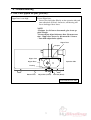
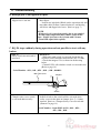
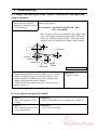
1
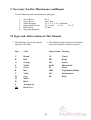
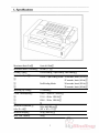
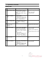
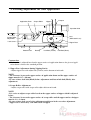
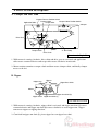
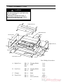
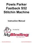
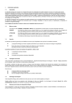
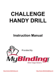
Standard BQ-P6
Binder Padder and
Spine Taper
Service Manual
Provided By
http://www.MyBinding.com
http://www.MyBindingBlog.com
SERVICE MANUAL
BQ-P6 Perfect Binder
510 Kuze Ooyabu-cho Minami-ku, Kyoto 601-8206, Japan
Phone:+81-75-934-6700, Fax:+81-75-934-6708, URL http://www.horizon.co.jp/
Kyoto,Japan
FOREWORD
Perfect Binder
Model BQ-P6
This manual is designed to help you to keep the machine in a good operating
condition. Read, study and keep this manual in a safe and convenient place.
Do not perform any maintenance until you read and
understand the instructions in this manual.
If you have questions regarding maintenance or this publication,
please contact our service division.
The machine design and specifications are subject to
change without notice.
060905/BQP6/04E/DV
I
US502007-04
Safety Instruction
1. Read and understand all safety instructions with a signal
WARNING,
CAUTION. If safety instructions are ignored, personal injury will
and
result.
2. HORIZON INTERNATIONAL INC. cannot anticipate every possible situation that might involve a potential hazard. The instruction in this manual are
therefore not all inclusive.
3. Be sure to unplug the power cord when replacing the parts or repairing the
machine.
4. Take care with the rotating parts when the machine is operated with the covers
being opened.
5. Use the original HORIZON spare parts when replacing the parts.
II
I Necessary Tool for Maintenance and Repair
Use the following tools for maintenance and repair.
1.
2.
3.
4.
5.
6.
Screw Driver
Screw Driver
Allen Wrenches
Open-ended Wrench
Box Wrench
Snap-ring Expander
No. 2
6 to 7 mm
1.5, 2, 2.5, 3, 4, 5, and 6 mm
5.5 x 7 mm
8 x 10
13 x 17
5.5 mm
II Signs and Abbreviations in This Manual
2. The following abbreviations in this manual
represent electronic and electrical parts.
1. The following signs in this manual
represent wire color.
Sign
Color
Abbreviation Meaning
C
R
O
Y
G
B
V
H
W
D
S
DH
Brown
Red
Orange
Yellow
Green
Blue
Violet
Gray
White
Black
Transparent
Dark Gray
CL
BK
SW
mSW
M
LED
VR
RY
III
Clutch
Brake
Switch
Microswitch
Motor
Light Emitted Diode
Potentiometer
Relay
Contents
FOREWORD .......................................................................................................................... I
Safety Instruction ................................................................................................................... II
I Necessary Tool for Maintenance and Repair ................................................................... III
II Signs and Abbreviations in this manual ........................................................................... III
1. Specifications ................................................................................................................... 1
2. Operation Procedure ...................................................................................................... 2
3. Leveling Adjustment for Glue Application ................................................................... 4
4. Drive Section Descriptions ............................................................................................. 5
5. How to Remove Cover .................................................................................................... 6
6. Troubleshooting ............................................................................................................... 7
7. Sensor and Electronic Parts Locations ......................................................................... 12
8. Switch Position Adjustment ........................................................................................... 13
9. Control P.C.B. LED Descriptions .................................................................................. 14
10. Electronic Circuit Diagram .......................................................................................... 15
11. Check Mode ................................................................................................................... 16
12. Melt Tank Replacement ............................................................................................... 17
IV
Maximum Book Size
Up to A4 Size
Maximum Book Thickness
25 mm ( 1" )
Binding Type
Cover Binding, Tape Binding and Padding
Production Speed
Cover / Tape Binding Mode: 30 seconds / book (50 Hz)
27 seconds / book (60 Hz)
Pad Binding Mode:
36 seconds / book (50 Hz)
33 seconds / book (60 Hz)
Warming Up Time
13 minutes
Power Consumption
100 V - 50/60 Hz 1050 W
115 V - 60 Hz 1050 W
230 V - 50 Hz 1050 W
Machine Dimentions
(W x D x H)
560 x 460 280 mm
(22" x 18" x 11")
Machine Weight
32 kg ( 64.8 lb )
Melt Tank Capacity
350 g
2. Operation Procedure
Cover/Tape Binding Mode
1
Operation
Action (Operation Panel LED)
Turn on power switch. - Heater begins to warm up.
- "Preparation" lamp illuminates.
- "Cover/Tape Mode" lamp
illuminates.
2
About 13 minutes
later.
3
Set sheets into
clamper.
Sensor or Switch
- Clamper home position switch
ON
- Nipper upper limit
microswitch OFF
- Alarm sounds.
- "Preparation" lamp goes out.
- "Insert stock. Depress start
button." lamp illuminates.
- Sheet presence microswitch
ON
Press start button.
- Nipper lower limit
- Nipper lowers and clamper
microswitch OFF
moves to the rear side and
- Clamper reverse switch ON
stops above melt tank while
"Operation" lamp is illuminating.
- "Operation" lamp goes out.
- "Place cover sheet. Depress
start button." lamp illuminates.
5
Set cover sheet or tape
and press start button
again.
- "Operation" lamp illuminates.
- Clamper goes back to home
position and stops on nipper.
- Nipper rises to nip cover
sheet and stock.
- Alarm sounds and nipper
lowers.
- "Operation" lamp goes out.
- "Take out stock. Depress
reset button." lamp illuminates.
6
Take out book.
7
Press reset button.
4
- Cover sheet sensor ON
- Clamper home position switch
ON
- Nipper lower limit
microswitch OFF
- Stock presence microswitch
OFF
- "Operation" lamp illuminates. - Nipper upper limit
microswitch OFF
- Nipper rises.
- "Operation" lamp goes out.
- "Insert stock. Depress start
button." lamp illuminates.
2
2. Operation Procedure
Padding Mode
Operation
Action (Operation Panel LED)
1
Turn on power switch. - Heater begins to warm up.
- "Preparation" lamp illuminates.
- "Cover/Tape Mode" lamp
illuminates.
2
About 13 minutes
later.
- Alarm sounds.
- "Preparation" lamp goes out.
- "Insert stock. Depress start
button." lamp illuminates.
3
Select binding mode.
- Lamp moves from "Cover/
Tape Mode" to "Padding
Mode".
4
Set sheets into
clamper.
5
Press start button.
6
Take out book.
7
Press reset button.
Sensor or Switch
- Clamper home position switch
ON
- Nipper upper limit
microswitch OFF
- Sheet presence microswitch
ON
- Nipper lowers and clamper
moves to the rear side and
stops above melt tank while
"Operation" lamp is illuminating.
- Alarm sounds
- "Operation" lamp goes out.
- "Take out stock. Depress
reset button." lamp illuminates.
- Nipper lower limit
microswitch OFF
- Clamper switch temporarily
ON
- Clamper home position switch
ON
- Stock presence microswitch
OFF
- "Operation" lamp illuminates. - Nipper upper limit
microswitch OFF
- Nipper rises.
- "Operation" lamp goes out.
- "Insert stock. Depress start
button." lamp illuminates.
3
3. Leveling Adjustment for Glue Application
Application Drum
Nippers
Scrape Roller
Clamper
Operation Side
Level 0
Scrape Roller
Adjust Bolt
Cam
(While stock is set.)
Pivot
Lock Screw
Nipper Base
Bottom Plate
Bearing
Lock Bolt (Yellow)
Lock Bolt (Black)
Construction
Each section is adjusted based on the upper surface of application drum as the pivot of application drum is fixed to the standard position.
1. Nipper Base Adjustment during Nipping Stocks
- Adjust nipper base with adjust bolt (Yellow) on the bottom of melt tank.
NOTE
- The clearance between the upper surface of application drum and the upper surface of
nipper must be 0.7 ~ 0.8 mm.
- Be sure to loose lock bolt (Black) before adjustment and fasten lock bolt (Black) after
adjustment.
2. Scrape Roller Adjustment
- Adjust scrape roller with scrape roller adjust bolt on melt tank.
NOTE
- It is easier to adjust scrape roller based on the upper surface of nipper which is adjusted
before.
- The clearance between the upper surface of scrape roller and the upper surface of nipper
must be 1.2 ~ 1.4 mm.
- Be sure to loose lock screw before adjustment and fasten lock screw after adjustment.
- Nipper base is lowered by cam while stock is nipped.
4
4. Drive Section Descriptions
A. Clamper and Melt Tank
Clamper Reverse Position Switch
Clamper Chain
Clamper Home Position Switch
Scrape Roller
Application Roller
Clamper
A
A
Drive Gear
A
Motor
Torque Clutch
A : Idler Pulley
Drive Chain
View from the Right Side
1. While motor is rotating clockwise, drive chain and drive gear are activated, and application
roller rotates counterclockwise and scrape roller rotates clockwise in melt tank.
2. Motor rotation transmitts to torque clutch and then rotates clamper chain, and finally clamper
moves to the left.
B. Nipper
Nippers
Nipper Arm
Nipper Base Shaft
Motor
Nipper Arm Shaft (R)
Nipper Chain
Nipper Arm Shaft (L)
View from the Left Side
1. While motor is rotating clockwise, nipper chain is activated, and nipper arm shaft (L) rotates
counterclockwise and nipper arm shaft (R) rotates clockwise to rotate nipper arm. Nipper
arms move nippers to nipping direction.
2. Cam fixed in nipper arm shaft (L) pivots nipper base on nipper base shaft.
5
5. How to Remove Cover
CAUTION
- Be sure to turn power off before any
cover is removed.
- Melt tank is heated up to 180 ˚C.
Wait until melt tank is cooled down
before covers are removed.
C
Clamp Cover (C)
C
C
Melt Tank Cover
B (Black)
C
Left Cover (B)
A (Black)
A (Black)
B
Right Cover (A)
B
D
A
D
Loosen
Nail
B (Black)
D
Control P.C.B.
D
Front Cover (D)
A
Loosen
Tool : Phillips Screwdriver
A
Right Cover
M4 x 12
M4 x 8
Nail
Tapping (Black)
Bind
2 pcs
2 pcs
1 pcs
B
Left Cover
M4 x 14
M4 x 8
Tapping (Black)
Bind
2 pcs
2 pcs
C
Clamper
M3 x 8
Bind
4 pcs
D
Front Cover
M4 x 8
M4 x 8
Screw
Screw (Loosen)
2 pcs
2 pcs
6
6. Troubleshooting
A. Glue is not applied on spine (partially).
(Cause)
Nipper base is too high.
(Remedy)
Lower nipper base.
Loosen two lock bolts (Black) on the operation side and
turn adjust bolt (Yellow) clockwise, and bearing will
lower and nipper base lower.
NOTE
- If nipper level is lowered too much, glue is not applied enough.
- Do not adjust adjust bolt more than 1/4 turn at one
time. Nipper base lowers by 0.1 mm with 1/4 turn.
- Turn both adjust bolts equally.
Nipper Base
Clamper
Nipper Cam
Nipper Base
Operation Side
Bearing
Bottom Plate
Adjust Bolt (Yellow)
Lock Bolt (Black)
View from the Left Side
7
6. Troubleshooting
B. Enough glue is not applied on spine.
(Remedy)
Rise nipper.
- Loosen two lock bolts (Black) on the operation side and
turn adjust bolt (Yellow) counterclockwise, and bearing
will lower and nipper base lower. (Refer to page 7.)
(Cause)
Nipper base is too low.
NOTE
- If nipper level is raised too much, glue is not applied .
- Do not adjust adjust bolt more than 1/4 turn at one
time. Nipper base lowers by 0.1 mm with 1/4 turn.
- Turn both adjust bolts equally.
C. BQ-P6 stops suddenly during operation and not possible to start with any
button.
(Cause 1)
Safety switch for melt tank is
activated.
(Remedy 1)
- When melt tank switch is activated, check that the
clearance between magnet and switch is 0.5~1.0 mm.
- Check that magnet is set as shown in the drawing
below.
- Control P.C.B. tells whether switch is activated or not.
(Refer to page 14.)
Serial Number : 039 -, 049 -, 059 -, 010 -, 020 -, 022001 Melt Tank cover
Magnet
30
5
Switch
(Cause 2)
Clamper safety cover switch
is activated unnecessarily.
(Remedy 2)
Adjust switch so that switch will be activated when
safety cover for the front of clamper rises 5 ~ 10 mm
upward. (Refer to "Clamper Safety Cover Switch Adjustment" in page 13.)
Serial Number : from 03915 to 039 -, 049 -, 058 -,
059 -, 010 -, 020 -
8
6. Troubleshooting
D. Clamper stops during operation. (Motor is making noise and application
drum is rotating.)
(Cause 1)
Torque clutch is adjusted
improperly, and drive power
is not transmitted.
Remedy 1)
Adjust torque again.
Serial Number : from 03915 to 03999, 049 -, 058 -,
059 -, from 01001
Move clamper to the far side by hand. Turn torque clutch
until click sound is heard from torque clutch. Then turn
further 60˚ and fasten plunger lightly. Turn back turque
clutch by 20 to 30˚ and then lock plunger with lock nut.
A : Idler Pulley
Lock Nut
Plunger
Torque Clutch
Motor
Drive Chain
View from the Left Side
(Cause 2)
Clamper home position switch or clamper reverse switch is
broken. If clamper stops at the far side, clamper reverse
switch is broken. If clalmper stops at the operation side,
clamper home position switch is broken.
- Control P.C.B. tells whether switch is activated or not.
(Refer to page 15.)
(Remedy 2)
Replace switch.
E. Cover sheet is not perfectly bound.
(Cause 1)
Glue is not applied on spine
enough.
(Remedy 1)
Refer to "Enough Glue is not applied on" in page 8.
(Cause 2)
Glue is dried because of slow
set up of cover sheet.
(Remedy 2)
Set cover sheet quickly.
9
6. Troubleshooting
F. One side of spine corner is not bent.
(Cause)
Nipper center and clamper
center are not aligned.
(Remedy)
Adjust nipper center and clamper center by moving
clamper home position switch. (Refer to page 12.)
Clamper Center
Nipper Center
(Cause)
Nipper center and clamper
center are not parallel.
(Remedy)
Remove clamper cover, loosen clamper fix bolts and
adjust clamper so that nipper and clamper are parallel.
Clamper Fix Bolts
G. All lamps on operation panel flash and BQ-P6 does not work.
(Cause)
Nipper does not work properly.
(Remedy)
Adjust the positions of nipper highest and lowest
position microswitches. (Refer to page 12.)
10
6. Troubleshooting
H. BQ-P6 does not work with "Preparation" LED illuminating.
(Cause 1)
Thermal fuse is blown.
(Remedy 1)
Replace thermal fuse. (167˚C)
NOTE
- Do not put excessive strength on terminal of thermal
fuse when replacing thermal fuse.
(Cause 2)
Heater is blown.
(Remedy 2)
Replace heater.
I. Glue is not appeared on application drum because glue becomes gel.
(Cause)
(Remedy)
Hot melt glue is not good to use. Replace glue.
J. The circuit protector trips when the power is turned on.
(Cause)
Internal circuit has a problem.
(Remedy)
Check the power circuit. Refer to the figure on page 15.
11
7. Sensor and Electronic Parts Locations
Drive Motor
Heater 1100W
Clamper Switch
Operation Panel P.C.B.QPW-417
Melt Tank Cover
Safety Switch
EGO Sensor
Clamper Home
Position Switch
Circuit Protector 8A/15A
Stock Presence
Microswitch
Nipper Upper Limit
Microswitch
Nipper Lower Limit
Microswitch
Nipper Safety Switch
Nipper Motor
Power Supply
Power Switch
Clamper Safety Cover Switch
Nose Filter
Control P.C.B. QPW-416
Cover Sensor
Clamper Safety Cover
12
8. Switch Position Adjustment
A. Nipper Upper / Lower Limit Microswitch Adjustment
Nipper upper limit microswitch :Adjust the position of switch cam so that microswitch is off
when the positions of nipper arms is either Fig. A or B.
(Refer to page 12.)
Nipper Arms
Nipper Arms
Fig. A
Fig. B
Touch
Nipper lower limit microswitch :Adjust the position of cam so that mcroswitch turns off
when nipper base is at the lower limit and also nipper up cam
is at the center of the lower limit.
B. Stock Presence Switch Adjustment
Adjust the position of stock presence switch
so that stock presence switch is stick out of
clamper by 0.5 to 0.7 mm while stock
presence switch is on.
Clamper
Stock Presence Switch
C. Clamper Safety Cover Switch Adjustment
Adjust clamper safety cover switch so that
switch turns on when clamper safety cover
is raised by 5 to 8 mm.
Clamper Cover
Clamper Knob
Clamper Safety Cover Switch
Nipper
Clamper Safety Cover
13
9. Control P.C.B. LED Descriptions
CON6
CON1
CON2
CON3
CON4
L4
L5 L6 L7 L8
L9 L10 L11 L12
L13 L14 L15 L16
L3
L2
ROM
L1
CON5
L1
L2
L3
L4
L5
L6
L7
L8
L9
L10
L11
L12
L13
L14
Nipper Up
Nipper Down
Clamper Home Position Switch
Clamper Reverse Switch
Nipper Home Position Switch
Nipper Lowee Limit Switch
Stock Presence switch
Cover Sheet Sensor
Start Switch
Stop Switch
Reset Switch
Padding or Cover/Tape Binding Switch
Clamper at Home Position
Melt Tank Cover
L15
L16
Clamper
Clamper Safety Cover Switch
14
Nipper rises from nipping position.
Nipper lowers to nip stock.
Illuminates at home position.
Illuminates at lowest position.
Illuminates when stock is not in clamper.
Illuminates when cover is used.
Illuminates by being pressed.
Illuminates by being pressed.
Illuminates by being pressed.
Illuminates by being pressed.
Illuminates at home position.
Illuminates when cover is closed.
S/N : from 03915 to 03999
049 -, 058 -, 059 010 -, from 02001 to 02047
Illuminates at reverse position.
Illuminates when cover is closed.
S/N : from 03915 to 03999
049 -, 058 -, 059 from 01001
15
LCA10S-5
Power Supply
PBF-1201-22
Noise Filter
SMP-04U-BC
CON1
CON2
CON5
Control P.C.B.
CON6
NC
COM
Clamper Safety Cover Switch
QPW-416
CON3
SMP-03U-BC
SMR-03U-B
1) CON4
Cover Sheet Sensor
Heater
NSKG115
ML-1765-6P
1-O
2-G
3-D
4-D
Capasitor
Nipper Safety Cover
NC
COM
2
4
1
EGO Sensor
NSKG115
W/H/D/DH
Nipper Motor
1-410318-B
1-410319-B
Power AC100V
1) BQ-P6 from No.03915 to No.02047 has melt tank cover sensor.
No.03001 or above BQ-P6 does not has melt tank sensor, but the same control P.C.B. is used by connecting No.3 and 4 pins on CON4.
2) No.03915 or above BQ-P6 has clamper safety cover switch.
3) No.022001 or above BQ-P6 has melt tank switch and nipper safety cover.
W
Drive Motor Capacitor
V
1-D
2-W
3-V
Nippe Upper
NC
Limit mSW COM
Nipper Lower
NC
COM
Limit mSW
Drive Motor
SMR-04U-B
COM
NC
Stock Presence
NO
Power Switch
Circuit Protector
SMP-02U-BC
SMR-02U-B
Clamper Home Position
SMR-02U-B
SMP-02U-BC
Clamper (Reverse)
COM
1) ,3) Melt Tanck Cover Sensor
10. Electronic Circuit Diagram
QPW 417
Panel P.C.B.
11. Check Mode
Turn on power switch during pressing start button.
- Padding or cover/tape binding mode lamps illuminate and the following actions are repeated
automatically; clamper moves, clamper reverse and nipper moves to nip stock.
Turn on power switch during pressing stop button.
- Padding mode and cover/tape mode lamps flash.
- Press start button, and clamper will move to far end position. Press start button again, and
clamper will return to home position.
- Press stop button, and nipper base will be raised to the highest position and then stopped in the
case that nipper base is at the lowest position or nipper base will be lowered to the lowest
position and then stopped in the case that nipper base is at the highest position.
- Press reset button, and nipper will move up and nip for 5 seconds and then stop at the lowest
position.
16
12. Melt Tank Replacement
Serial Number : 029 -, 039 -, 049 -, 059 -, 010 - and 020 -
CAUTION
- Melt tank and hot melt glue have been
heated very high temperature, so take
utmost care when replacing.
1. Remove melt tank cover and rear cover.
2. Disconnect heater connector.
3. Remove thermal adjuster (EGO senor).
4. Remove scrape roller adjust bolt.
5. Remove application drum bush.
Scrape Roller Adjust Bolt
Cap Screw (3 mm) (4 pcs)
6. Pull melt tank upward.
7. Remove DU bushes on the both sides of drum in melt tank. Those DU bushes will be used
when new melt tank is installed.
8. Install new melt tank in the reverse procedure of removing.
9. Adjust the upper surface of scrape roller as shown in the drawing below and then lock scrape
roller. If bolt length is not long enough, replace the bolt with accessory bolt.
Scrape Roller Adjust Bolt
0.5 to 0.6 mm
Spring
Lock Screw
17
12. Melt Tank Replacement
Serial Number : from 03001
CAUTION
- Melt tank and hot melt glue have been
heated very high temperature, so take
utmost care when replacing.
1. Remove melt tank cover and rear cover.
2. Disconnect heater connector.
3. Remove thermal adjuster (EGO sensor).
4. Remove scrape roller adjust bolt.
(Hold spring when adjust bolt is removed.)
5. Remove screws which fix application drum bush.
Application Drum Bushes
The Left Side of Melt Tank
The Right Side of Melt Tank
6. Pull both application drum bushes to the thrust direction while melt tank is held.
7. Pull melt tank upward.
8. Install melt tank in the reverse procedure of removing.
9. Adjust the upper surface of scrape roller as shown in the drawing below and then lock scrape
roller.
0.5 to 0.6 mm
Scrape Roller Adjust Bolt
Spring
Lock Screw
18