1
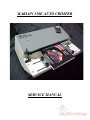
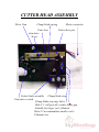
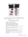
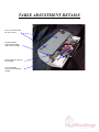
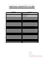
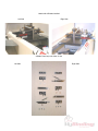
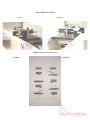
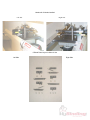
Marlon 350E
Auto Crimper
Service Manual
Provided By
http://www.MyBinding.com
http://www.MyBindingBlog.com
MARLON 350E AUTO CRIMPER
SERVICE MANUAL
INTRODUCTION
Your new Marlon 350 Auto Crimper is designed to increase
your plastic spiral binding production. The Marlon 350 is an
inexpensive yet extremely versatile tabletop machine. The Marlon
350 cuts and crimps 6mm through 50mm coil, with an adjustable
binding length from 3.5-inches to 14-inches. The Marlon 350 is
capable of 50 cycles per minute, and features a coil waste chute
that uses standard plastic grocery bags for clipping waste
containment. The Marlon 350 is an operator friendly machine that
is easy to set up, allowing for quick changeover from one coil
diameter to another. We are confident that your new Marlon 350
Auto Crimper will be a valuable asset to your plastic coil binding
operation.
The following pages of this manual will cover machine setup,
operating procedures, and trouble shooting your Marlon 350 Auto
Crimper.
WARNING: Changing of cutting blades should be
done only by trained service personnel. Disconnect
power from unit before servicing.
MARLON 350E CONNECTIONS
Power switch
AC - in
Foot pedal-out
AC-fuse
DC-fuse
COIL WASTE CHUTE
PLACE BAG
HANDLES IN
THESE SLOTS
TO HOLD BAG
THE COIL WASTE CHUTE USES STANDARD PLASTIC GROCERY BAGS
FOR CLIPPING CONTAINMENT. PLACE THE HANDLES OF THE BAG
IN THE SLOTS ON BOTH SIDES TO HOLD THE BAG IN PLACE.
BLADE SELECTION
The Marlon 350 Auto Crimper features interchangeable
cutter blades. Your Marlon 350 was shipped with the B-size cutter
blades installed. Use the following chart to determine what blade
size is required for the coil diameter your crimping.
A-size blades: 6mm and 7mm coil
Note: Over sized punch patterns (.248) or punch patterns with a large backstop (distance
from paper edge to hole) will not work well with the A – size cutter head.
B-size blades: 8mm through 25mm coil
C-size blades: 12mm through 50mm coil
The cutter blades and cutter head assemblies have been color
coded to reduce the chance of improper assembly.
Universal parts of the cutter head assembly that are used for all
three sets of knives are marked white. These parts are used all of
the time.
1.)
2.)
A-size parts of the cutter assembly are marked red.
3.)
B-size parts of the cutter assembly are marked green.
4.)
C-size parts of the cutter assembly are marked yellow.
Note: Some parts of the cutter assembly are marked with two
colors. These parts are used on two of the three cutter
assembly configurations.
CUTTER HEAD ASSEMBLY
Drive Cam
Clamp blade spring
Cam Arm
Arm drive
Screw
Motor connector
Cutter drive pin
Cutter blade assembly
Clamp blade stop
Cam micro switch
Clamp blade stop mtg. holes 1, 2
Hole # 1, will provide a wider blade gap
Suitable for larger coil / filament
Hole # 2 accommodates smaller coils /
Filament size
B-SIZE CUTTER BLADE ASSEMBLY
LEFT CUTTER HEAD
RIGHT CUTTER HEAD
LEFT BASE PLATE
A, B & C – SIZE ANVIL BLADE
RIGHT BASE PLATE
B – SIZE .126” SPACERS
CLAMP SPRING
B – SIZE CUTTER BLADE
B & C – SIZE CLAMP BLADE
B & C – SIZE-FORMING BLADE
B & C – SIZE-FORMING BLADE
CLAMP SPRING
B – SIZE CUTTER BLADE
B & C – SIZE CLAMP BLADE
B – SIZE .126” SPACERS
CLAMP STOP 1/4 X 1-1/2
SHOULDER BOLT
A, B & C – SIZE ANVIL BLADE
FOR B – SIZE ASSEMBLY
ONLY .062 SPACER
CLAMP STOP 1/4 x 1-1/2
SHOULDER BOLT
10-24 NYLOCK NUTS
10-24 NYLOCK NUTS
NOTE: THE RIGHT CUTTER BLADE ASSEMBLY IS UP SIDE
DOWN. THE SAME FOUR BLADES ARE USED ON BOTH SIDES,
BUT THEY ARE INSTALLED IN EXACTLY THE OPPOSITE ORDER.
Pictured above is the B-size cutter blade assembly. The following information describes the
changes needed to switch from the B to A-size and B to C-size cutter assemblies. Refer to the color codes
on page four to select the proper parts when changing from one blade configuration to another. Refer to
pages five and six for part descriptions.
Changing from B to A-size blades:
1.)Disconnect the power cord from Marlon 350.
2.)Remove the top cover from the machine.
3.)Remove the clamp stop shoulder bolts from each side
4.)Remove the three 10-24 nylock nuts from each side.
5.)The left clamp blade is now free and can be removed.
6.)Remove the right anvil blade by lifting it straight up.
7.)Remove the left forming blade by lifting it straight up.
8.)Detach the right cutter blade from the drive pin. (the right cutter blade is now
free.)
9.)Remove the two .126” B-size spacers from each side.
10.)Remove the right forming blade by lifting it straight up. The right clamp
blade is now free.
11.)Detach the left cutter blade from the drive pin, the arm drive screw must be
loosened to free cutter blade. (See step 8 for details.)
12.)Leave the left anvil blade on, because it’s used in all three setups.
13.)Reassemble the cutter blade assemblies in reverse order using the correct
color-coded parts.
14.)Use the fifth .094” A-size spacer instead of .062spacer on the left hand
shoulder bolt.
A-KIT COIL GUIDE INSTALLATION
PICTURED ABOVE ARE THE COIL GUIDES INSTALLED ON
THE CUTTER ASSEMBLY. THESE GUIDES ARE ONLY USED
WITH THE A-SIZE BLADE CONFIGURATION. THE COIL
GUIDES ARE STAMPED “L” FOR LEFT AND “R” FOR RIGHT
AND ARE ALWAYS INSTALLED WITH THE LETTERS UP. YOU
HAVE TWO “L” GUIDES ONE MARKED
“L” AND ONE MARKED “L 6”. THE “L 6” IS USED FOR
6mm DIA. COILS ONLY.
Changing from B to C-size blades:
1.)Disconnect the power cord from Marlon 350.
2.)Remove top cover from machine.
3.)Remove the clamp stop shoulder bolts on both sides.
4.)Remove the three 10-24 nylock nuts from each side.
5.)The left clamp blade is now free and can be removed.
6.)Remove the right anvil blade by lifting it straight up.
7.)Remove the left forming blade by lifting it straight up.
8.)Detach the right cutter blade from the drive pin. (The right
cutter blade is now free.)
9.)Remove the two .126” B-size spacers from each side.
10.)Remove the right forming blade by lifting it straight up. The
right clamp blade is now free.
11.)Detach the left cutter blade from the drive pin, the arm
drive screw must be loosened to free cutter blade (See step 8
for details.)
12.)Leave the left anvil blade on, because it is used in all three
setups.
13.)Change the clamp stop to its correct hole position.
14.)Reassemble the cutter blade assemblies in reverse order
using the correct color-coded parts.
15.)Note: No washers or spacer is used on the left-hand
shoulder bolt when using the C-size blade configuration.
C-CUTTER BLADE INSTALLATION
REAR HOLE OF THE
C-CUT BLADE IS
NOT USED IN THIS
MODEL.
IN YOUR “C” KIT
THIS HOLE IS
PLUGGED.
INSTALL THE DRIVE
PIN IN THE OPEN
HOLE.
PICTURED ABOVE ARE THE C-SIZE CUTTER BLADES AS
FURNISHED IN THE “C” KIT SHIPPED WITH YOUR
MACHINE.
CLAMP STOP POSITIONS
Mount the clamp stop in the first hole for C-size blade configuration.
Mount the clamp stop in the second hole for A and B-size blade
configurations.
These stop positions allow adjustment of blade opening for coil
Insertion and the above are suggested settings. Some B size coils
Might work well in the first hole position. Filament size and coil
Pitch will be the factors involved.
TABLE ADJUSTMENTS
Now that you have the correct blade configuration ready for the coil
diameter you are crimping you need to adjust the table height and cutter
head spacing (width) for your book. Refer to page 13 for table adjustment
details.
1.)Loosen the two clamp knobs on the left-hand book guide; position the
guide so your book will be approximately centered on the machine. Re
tighten the two clamp knobs.
2.)Using the same procedure position the right-hand book guide so it just
touches the right edge of the book. The book should lay flat on the table
between the book guides and be able to slide in and out, but not side to side.
3.)Use a #3 Phillips screwdriver to loosen the two bolts located under the
two access holes in the top cover. The two cutter heads will now be able to
slide from side to side. Slide the two cutter heads so the cutter blades are
close to the correct loop of the coil at each end of the book.
4.)Make a rough adjustment on the table height by turning the two table
height knobs. Turn the knobs clock-wise to lower the table and counter
clock-wise to raise the table. Adjust the table height so the coil in the book is
in the center of the cutter blade assembly on both sides. The right side of the
table will always be adjusted higher than the left side.
5.)Adjust the two cutter heads from side to side until the coil in the book
slides into the cutter blades at the correct loop of the coil on each side of the
book
6.)Make a finer adjustment to the table height so the coil in the book is
properly positioned in the center of the cutter blades.
7.)Make your final cutter head adjustments side to side if needed and then re
tighten the two bolts under the access holes of the top cover using the #3
Phillips screwdriver.
8.)Test crimp a book by depressing the foot pedal.
9.)Make your final table height adjustments if needed. Then repeat steps #8
and #9 until the desired crimp is achieved.
TABLE ADJUSTMENT DETAILS
TWO ACCESS HOLES
IN TOP COVER
TABLE HEIGHT
ADJUSTER KNOBS:
ONE ON EACH SIDE
BOOK GUIDES: ONE ON
EACH SIDE
CLAMP KNOBS:
TWO ON EACH BOOK
GUIDE
TROUBLE SHOOTING GUIDE
PROBLEM
CRIMPER DOESN’T CYCLE
COIL IS BEING CRIMPED BUT NOT
CUT
POWER ON DOESN’T CYCLE
SOLUTION
VERIFY THAT POWER IS PLUGGED IN
AND TURNED ON
ADJUST TABLE HEIGHT FOR PROPER
ALIGNMENT
RESET FUSES
Heads with A-Blades installed
Left Side
Right Side
A-Blade Parts Layout in Order of Use
Left Side
Right Side
Heads with B-blades installed
Left Side
Right Side
B-Blade Parts Layout in Order of Use
Left Side
Right Side
Heads with C-blades installed
Left Side
Right Side
C-Blade Parts Layout in Order of Use
Left Side
Right Side
MARLON 350E AUTO CRIMPER
MARLON INC.
123 EAST 45TH STREET
BOISE, IDAHO 83714
Ph 1-(800) 461-9301
Fax 1 (208) 321-2796