1
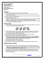
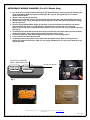
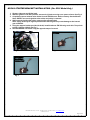
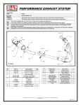
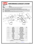
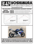
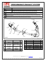
PERFORMANCE EXHAUST SYSTEM
APPLICATION
YEAR
MODEL
2011-2012
PRODUCT
1160003221
1160003521
1160003551
Suzuki GSX-R600 / 750
R77D Stainless Steel Full System Exhaust System with Carbon Fiber Sleeve; Carbon Fiber Endcap
R77D Stainless Steel Full System Exhaust System with Stainless Steel Sleeve; Carbon Fiber Endcap
R77D Stainless Steel Full System Exhaust System with Stainless Steel Sleeve; Stainless Steel Endcap
This product is designed for use in closed course racing and is not intended for highway use.
In the state of California, it is illegal to modify the emission control system, which includes the fuel injection of any vehicle.
You must know how to remove and replace your stock exhaust in order to install this product otherwise have it installed by a professional
mechanic. Keep all stock parts from your existing system as some components may be necessary to install your new Yoshimura exhaust
depending on the application.
Read through all instructions before beginning installation. Exhaust system can be extremely hot. Let motorcycle cool down before beginning
installation. Always wear hand and eye protection and take precautionary measures to avoid injury.
6 x4
12
7 x4
4
S
9
S
11
9 x2
10
5
3
8 x4
9
2
S
9 x4
S = Stock
No.
Part #
Description
Qty
1
11600-404
Yoshimura Header
1
2
11600-419
Yoshimura Tailpipe
1
Yoshimura Muffler
CF Sleeve; CF Endcap
SS Sleeve; CF Endcap
SS Sleeve; SS Endcap
Muffler Clamp
CF Sleeve
SS Sleeve
Muffler Clamp
Heatshield
Yoshimura Manifold
1
3
CRR77D126W
SRR77D126W
SRR77D126W-SS
4
5
1121-MPCA
1121-MPCAX
HT SHLDR77
6
1228SMT
5420 Daniels Street Chino, CA 91710
1
1
7
8
9
10
11
1170SDY
RACE-SPX-1
RACE-SPS-1
8MMNUT
M8X45
12
**
**
**
**
**
M8ALCSW-00
11600-RAD-BRKT
11600-CKRPLT
ST-200
OXYBA12X125SS
17029
1
Yoshimura Flange
Short Spring
Medium Spring
8mm Flange Nut
8mm x 45mm
Soc Head Cap Screw
M8 Counter Sink Wshr.
Radiator Bracket
EXCVA Stopper Plate
Spring Puller Tool
O2 Bung Adapter
Yoshimura Sticker Sht
4
4
8
1
1
1
1
1
1
1
1
4
Tel (800) 634-9166 Fax (909) 591-2198 www.yoshimura-rd.com
1160003(221,521,551)
Page 1 of 4
-TOOLS REQUIRED-
Metric Socket Set
Combination Wrench Set
Torque Wrench
Metric Allen Wrench Set
Screwdriver
-REMOVAL-
1. Remove left and right side fairing as per Factory Service Manual.
2. Remove stock muffler by loosening exhaust clamp and while securely supporting the muffler,
3.
4.
5.
6.
remove muffler mount bolt.
Remove lower radiator support bracket and swing radiator forward to ease removal of stock header.
Remove O2 sensor from stock header.
Remove exhaust valve cables.
NOTE: Stock exhaust valve cables will not be used with Yoshimura Full System Exhaust. For 2011
model, see wiring change. For 2012 model, see EXCVA stopper installation.
Carefully remove stock header and exhaust port gaskets. (Note: Yoshimura Full System is designed
to be installed without exhaust port gaskets.)
-INSTALLATION-
1. Install Yoshimura manifolds and flanges into exhaust ports using stock header bolts. Torque to 7.3
ft-lb. (10 Nm, 1.0 kgf-m) See flange orientation below.
2. Install Yoshimura header from one end of the engine to the other by slipping one header leg at a
time onto manifolds. (Note: Lightly tap header legs with a plastic mallet to ensure a tight fit.)
Connect header to flanges using the supplied springs.
Install chassis mount bolt to secure header. Torque to 16.5 ft-lb. (23 Nm, 2.3 kgf-m)
Slide Yoshimura muffler and tailpipe assembly onto header.
Install rubber heat insulator onto Yoshimura muffler clamp. Slide muffler clamp over muffler and
install muffler clamp to the inside of the stock muffler mount bracket using supplied hardware.
See diagram for orientation. (Note: Twisting of tailpipe may be necessary for proper alignment. If
needed, remove muffler springs to twist tailpipe for proper alignment.)
7. Install springs on tailpipe to header connection.
8. Re-install stock O2 sensor onto Yoshimura header.
9. Re-install radiator bracket. (Note: For GSX-R750, use provided Yoshimura radiator bracket.)
3.
4.
5.
6.
-FITMENT CHECK & NOTES1. Before starting motorcycle, check for proper clearance between new exhaust system and rear
suspension (i.e. tire, swing-arm, brake, rear shock, engine, and etc.) If any problem is found, please
carefully follow through the installation steps again. If problem still persists, please call Yoshimura
Tech Department at (800) 634-9166 / in CA (909) 628-4722.
2. It is recommended that the muffler and tailpipe be wiped down with rubbing alcohol to remove oil
and fingerprints. This will help prevent tarnishing of the finish after the exhaust is heated up.
3. NOTE: After starting motorcycle, it is normal for new exhaust system and muffler to emit smoke
until oil residue burns off.
5420 Daniels Street Chino, CA 91710
Tel (800) 634-9166 Fax (909) 591-2198 www.yoshimura-rd.com
1160003(221,521,551)
Page 2 of 4
-NECESSARY WIRING CHANGES- (For 2011 Model Only)
1. It is necessary to properly disable the Suzuki SET (Suzuki Exhaust Tuning) system by following the
steps listed below. Without properly disabling the SET system, the engine will run in a power
limited fail-safe mode.
2. Remove rider seat and lift fuel tank.
3. With ignition in the OFF position, disconnect the black wire harness plug from the ECU. See Fig. 2
4. Remove the orange cap by pressing the small orange tabs on the side apart and pulling the orange
cap off. See Fig. 3
5. Remove #5 wire (Brown/Black Stripe) by inserting a very small flat head screwdriver into the pin
hole and gently pry down to unlock the wire and pull the wire out from the rear of the plug.
(Note: If you do not have a small flat head screwdriver, you can make one using a regular paper clip.
See Fig. 4)
6. Completely seal off the disconnected wire using electrical tape and shrink tube to prevent possible
electrical problems. Secure disconnected wire to harness using a zip tie.
7. Re-install orange cap onto black wiring harness plug and re-connect plug to ECU.
8. Lower fuel tank and re-install rider seat.
9. Completely remove the exhaust valve cables from the EXCVA servo. Refer to Factory Service
Manual for removal instructions. (Note: Do not unplug EXCVA servo as it may cause the bike to run
in fail-safe mode.
5th pin from the right side.
(Brown / Black Stripe Wire)
1st row from the top.
Disconnect black
plug
Fig. 1
Fig. 2
Use a hammer
to make
a flat head
Fig. 3
Fig. 4
5420 Daniels Street Chino, CA 91710
Tel (800) 634-9166 Fax (909) 591-2198 www.yoshimura-rd.com
1160003(221,521,551)
Page 3 of 4
-EXCVA STOPPER BRACKET INSTALLATION- (For 2012 Model Only)
1. Remove rider seat and lift fuel tank.
2. With the ignition in the OFF position, remove the (2) bolts securing servo motor to frame. See Fig. 5
3. Completely remove exhaust valve cables from the EXCVA servo. Refer to Factory Service Manual.
Note: DO NOT turn on the ignition when cables and pulley is removed.
4. While securely holding the pulley, remove pulley mounting bolt.
Note: Pulley must stay in original position when removing bolt to prevent damage to the internal
gear of EXCVA.
5. Using the stopper bracket provided in the kit, install bracket to EXCVA using stock bolt. Torque bolt
to 5Nm. (0.5kg-m,3.5lb-ft) See Fig. 7
6. Reinstall EXCVA onto frame using the opposite steps of removal.
Stock
Fig. 5
Fig. 6
Stopper
Bracket
Installed
Fig. 7
5420 Daniels Street Chino, CA 91710
Tel (800) 634-9166 Fax (909) 591-2198 www.yoshimura-rd.com
1160003(221,521,551)
Page 4 of 4