1
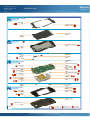
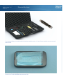
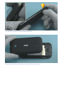
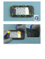
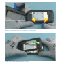
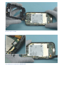
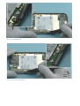
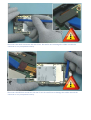
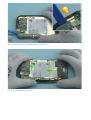
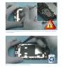
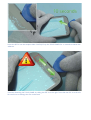
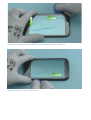
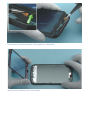
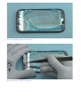
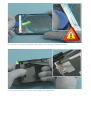
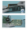
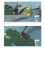
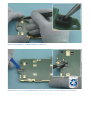
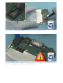
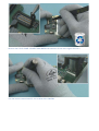
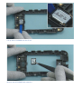
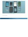
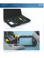
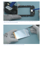
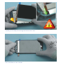
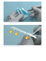
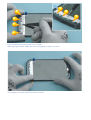
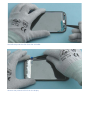
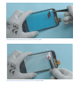
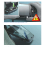
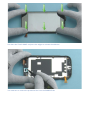
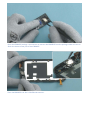
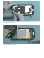
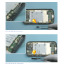
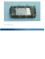
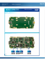
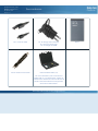
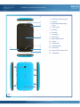
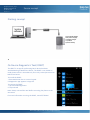
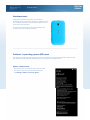
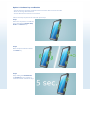
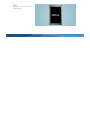
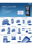
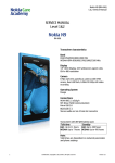
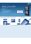
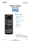
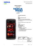
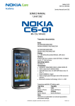
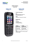
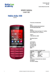
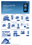
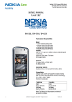
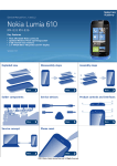
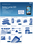
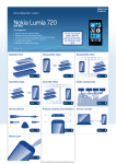
Service Manual for L1 and L2
Nokia Lumia 510
RM-889 RM-898
Key features
z
z
z
z
z
Windows Phone 7.5 / 7.8 OS
Large 4" display
5 Megapixel camera
800 MHz Snapdragon processor
256 MB RAM, 4GB internal storage + SkyDrive
Check the repair
policy before
performing any
mechanical repair
on Service Level
1&2!
Version 1.0
Exploded view
Disassembly steps
More
Assembly hints
Disassembly video
More
Assembly video
More
Service devices
Solder components
More
Product controls and interfaces
More
More
More
Phone reset
More
©2012 Nokia | Nokia Internal Use only | All Rights Reserved.
More
Service concept
More
Service Manual Level 1 and 2
Exploded view
Nokia Lumia 510
RM-889 RM-898
Version 1.0
TOUCH PANEL ASSEMBLY
(I0001, I0002)
TOUCH PANEL
I0002
TP/LCM SPONGE
I0001
LIGHT GUIDE
I0004
DISPLAY
I0003
2
A-COVER ASSEMBLY
(I0005, I0006)
TOUCH PANEL ADHESIVE
I0005
A-COVER
I0006
3
CAMERA KEY
I0009
POWER KEY
I0010
EARPIECE
I0007
VOLUME KEY
I0008
MIC RUBBER
I0015
LIGHT SWAP PACKAGE
(I0011-I0023)
SEARCH KEY LED SPONGE
I0020
BACK & HOME
KEY LED SPONGE
I0019
SPEAKER SEALING SPONGE
I0021
LCD CONNECTOR RUBBER
I0017
MYLAR USB
I0023
PROXIMITY SENSOR RUBBER
I0016
MYLAR RECEIVER
I0022
LIGHT SWAP PWB
I0011
RF SHIELD
I0012
TP CONNECTOR RUBBER
I0018
TYPE LABEL
I0014
4
BASEBAND SHIELD
I0013
CAMERA
I0024
IHF SPEAKER
I0025
D-COVER ASSEMBLY
SPEAKER MESH
I0026
(I0026-I0029)
GPS ANTENNA
I0028
MAIN ANTENNA
I0027
D-COVER
I0029
BATTERY COVER
I0031
SCREW TORX+ SIZE 5
I0030
v1.0
Only available
as assembly
©2012 Nokia | Nokia Internal Use only | All Rights Reserved.
Not reuseable
after removal
Repair/swap
only in level 3
Service Manual Level 1 and 2
Nokia Lumia 510
RM-889 RM-898
Version 1.0
Disassembly steps
For disassembling you need the Nokia Standard toolkit version 2. You will also need the camera removal
tool SS-287.
Protect the TOUCH SCREEN with protective film.
Use the finger groove to release the BATTERY COVER.
Remove the BATTERY COVER. If there is a battery inside, remove it also.
Unscrew the eight TORX+ size 5 screws in the order shown. Do not use the screws again. Discard them.
Use the srt-6 to release these two snaps.
Release also these two snaps on the the other side of the device.
Lift up the D-COVER ASSEMBLY bottom end first.
Remove the D-COVER.
Use tweezers to remove the CAMERA KEY.
Remove the POWER KEY.
Remove also the VOLUME KEY.
Disconnect the touch connector with the SS-93. Be careful not to damage the rubber around the
connector or any components nearby.
Disconnect the DISPLAY connector with the SS-93. Be careful not to damage the rubber around the
connector or any components nearby.
Release the clip holding the ENGINE BOARD with the SS-93.
Lift up The ENGINE BOARD as shown.
Carefully release the EARPIECE with the dental tool. Be careful not to injure yourself with the sharp end
of the dental tool.
Remove the EARPIECE. Do not use it agin. Discard it.
Insert the SRT-6 into the earpiece hole. Carefully lift up the TOUCH PANEL for 10 seconds to loosen the
adhesive.
Continue detaching the TOUCH PANEL by sliding the SRT-6 to the right. Then slide the SRT-6 to the left.
Be careful not to damage the flex underneath.
Continue by releasing the TOUCH PANEL side and the bottom end with the SRT-6.
Release also the other side with the SRT-6.
Use tweezers to pull the connector flex through the A-COVER hole.
Separate the A-COVER and the TOUCH PANEL.
Protect the DISPLAY with protective film.
Remove the LIGHT GUIDE with tweezers.
Use the SRT-6 to release the DISPLAY. Be careful not to damage the flex underneath.
Use tweezers to put the connector flex through the A-COVER hole.
Separate the A-COVER and the DISPLAY. Note that the A-COVER can not be used again.
Remove the MIC RUBBER with tweezers.
Remove the SEARCH KEY and the BACK & HOME KEY LED SPONGEs with tweezers. Do not use them again.
Discard them.
Peel off the MYLAR USB with tweezers. It is not reusable. Discard it.
Remove the PROXIMITY SENSOR RUBBER with tweezers.
Release one corner of the MYLAR RECEIVER with the SS-93. Peel it off with tweezers and discard it.
Remove the LCD CONNECTOR RUBBER with tweezers. Do not use it again. Discard it.
Release the SPEAKER SEALING SPONGE with the SS-93. Remove it with tweezers. Do not use it again. Be
careful not to damage the components on the ENGINE BOARD.
Remove the TOUCH PANEL CONNECTOR RUBBER with tweezers. Do not use it again. Discard it.
Use the camera removal tool SS-287 to detach the CAMERA.
Lift up the IHF SPEAKER with the SS-93.
Remove the IHF SPEAKER with tweezers.
The Nokia Lumia 510 disassembly procedure is complete.
-END OF DISASSEMBLY-
©2012 Nokia | Nokia Internal Use only | All Rights Reserved.
Service Manual Level 1 and 2
Nokia Lumia 510
RM-889 RM-898
Version 1.0
Assembly steps
For assembling you need the Nokia Standard toolkit version 2.
Place the IHF SPEAKER into the D-COVER. Make sure the IHF SPEAKER is aligned correctly. The pins should
point towards the cavity with arrow on it.
Press the IHF SPEAKER gently from the black plastic parts to activate the adhesive. Make sure not to
touch the center part of the IHF SPEAKER.
Remove the protective film from the back side of the display.
Carefully put the display flex through the hole on the A-cover.
Place the DISPLAY to the A-COVER.
Use tweezers to pick up a new LIGHT GUIDE.
Bend the transparent appendices with fingers.
Insert the bent parts into the holes on A-COVER.
While aligning the LIGHT GUIDE use the round guidings to align it correctly.
Press slightly the LIGHT GUIDE to attach it correctly.
Peel off the protective film from the A-COVER.
Remove the protective film from the display.
Peel off the first protective film from the TOUCH PANEL.
Peel off the second protective film from the TOUCH PANEL.
Carefully put the touch panel flex through the hole on the A-cover.
Place the top side of the TOUCH PANEL to the A-COVER.
Put down the TOUCH PANEL and press the edges to activate the adhesive.
Use tweezers to remove the protective film from the EARPIECE slot.
Open the EARPIECE package. Use tweezers to remove the EARPIECE from the package. Make sure not to
touch the shown center part of the EARPIECE.
Place the EARPIECE into the A-COVER with tweezers.
Press the EARPIECE gently from the black plastic parts to activate the adhesive. Make sure not to touch
the center part of the EARPIECE.
Place the CAMERA KEY with tweezers.
Place the POWER KEY with tweezers.
Place the VOLUME KEY with tweezers.
Fasten the eight TORX+ size 5 screws to the torque of 10 Ncm.
-END OF ASSEMBLY HINTS-
©2012 Nokia | Nokia Internal Use only | All Rights Reserved.
Service Manual Level 1 and 2
Nokia Lumia 510
RM-889, RM-898
Version 1.0
Solder components
NOKIA LUMIA 510
Solder components
RM-889, RM-898
BOTTOM
SK3703
SK3704
Volume +
switch
Volume switch
SK3702
switch
Camera
switch
v1.0
©2012 Nokia | Confidential | All Rights Reserved.
Service Manual Level 1 and 2
Nokia Lumia 510
RM-889 RM-898
Version 1.0
Service devices
CA-101 Service cable
AC- 8C Charger (for China only)
AC-10UC (for Taiwan only)
AC-20 Charger (for RoW)
SS-287 Camera removal tool
Nokia Standard Toolkit (v2)
For more information, refer to the Service
Bulletin (SB-011) on Nokia Online. Supplier or
manufacturer contacts for tool re-order can be
found in “Recommended service equipment”
document on Nokia Online.
©2012 Nokia | Nokia Internal Use only | All Rights Reserved.
BP-3L
Service Manual Level 1 and 2
Nokia Lumia 510
RM-889 RM-898
Version 1.0
Product controls and interfaces
1
1 — Nokia AV 3.5 mm connector
2
2 — Earpiece
3
3 — Proximity & Ambient light
sensor
4 — Touch screen
5 — Back key
6 — Start key
7 — Search key
4
8 — Microphone
9 — Micro USB connector
10 — Camera
6
5
11 — Volume keys
12 — Lock/Power key
7
13 — Camera key
8
14 — Battery cover release notch
9
15 — Loudspeaker
10
11
12
13
14
15
v1.0
©2012 Nokia | Nokia Internal Use only | All Rights Reserved.
Service Manual Level 1 and 2
Nokia Lumia 510
RM-889 RM-898
Version 1.0
Service concept
Flashing concept
Service
software
CA-101
Care Dummy Battery
with power supply
via Nokia charger
or product
specific battery
Transceiver
On Device Diagnostics Tool (ODDT)
The ODDT is an app for performing basic device hardware
troubleshooting at Nokia Care Points. The ODDT is not visible on
retail phones and it is intended only for use by trained personnel at
Nokia Care Points.
To install the ODDT:
1. Enter ##634# on the on-screen keypad
2. Diagnostics app appears in Apps list
To remove the ODDT:
1. Tap and hold Diagnostics
2. Tap uninstall
Note: always uninstall the tool before returning the phone to the
consumer!
For more information on using the ODDT, see KICS TR2816.
©2012 Nokia | Nokia Internal Use only | All Rights Reserved.
Service Manual Level 1 and 2
Nokia Lumia 510
RM-889 RM-898
Version 1.0
Phone reset
Hardware reset
If the phone hardware is jammed, you should first
recommend that the consumer performs a hardware reset.
The hardware reset does not reset the Windows Live ID or
remove any consumer data.
To perform a hardware reset remove the battery and
reinsert it. Boot up the phone normally.
Software / operating system (OS) reset
The software / operating system (OS) reset returns the phone to its out-of-the-box state. Note that this
procedure erases all consumer data! Always first try to perform a hardware reset.
Option 1: About menu
- Use this option if the consumer knows the lock code
- This option warns the consumer about data loss!
- Tap Settings > About > reset your phone
Option 2: Hardware key combination
- Use this option if the phone is locked and the consumer does not know the code
- Note: no warning about data loss!
- Do not advertise this feature to consumers!
Follow next steps to perform OS reset with phone keys.
Step 1
Make sure the phone is turned Off.
Press and hold the Volume down,
Power and Camera keys
Step 2
When the phone vibrates release
the Power key
Step 3
Keep holding the Volume down
and Camera keys for another 5
seconds and then release the keys
Step 4
The phone will reset and boot up
automatically
©2012 Nokia | Nokia Internal Use only | All Rights Reserved.
Service Manual Level 1 and 2
Version history
Nokia Lumia 510
RM-889 RM-898
Version 1.0
Version
Date
Description
1.0
23.10.2012
First published version
©2012 Nokia | Nokia Internal Use only | All Rights Reserved.