1
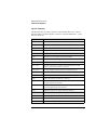
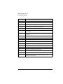
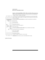
SONET/SDH
TESTSETS
Communications
Performance Analyzers, SDH/PDHTest Set
HP377178,37717C,37724A
. Single-unitsolution tor SDH/PDH/ATM Test. endiitter generation
.
and test
In-service end out-ot-service measurements
. Monitors PDHand SDHoverheadframing, parity,
and alarm information
.
.
Easy results interpretation with new color interface
. ATM ce!! generation and analysis,and ATM services Ilyertest
. Pointer sequence generationto ITU-T G.783
Works with HPE4540Adistributednetwork analysissoftware
With compliments
Helmut Singer Elektronik
www.helmut-singer.de [email protected]
fon +49 241 155 315
fax +49 241 152 066
Feldchen 16-24 D-52070 Aachen Germany
HP37717C
HP37717B/CCommunicationsPerformance
Analyzers
These offer modular, upgradeable one-box solutions tor installation, fjeld
maintenance, commissioning and manufacturing. RIIgged and portable, they
aIlowfullfunctional tesQngofSDH. PDH andATM equipment. includingjitter. The HP 37717C has color dispIay and grapbics IXinter. The HP3'Tl178
monochrome version provides a budget solution. wid1 a 2~lumn
printer.
80th have a 3.>inch disk drive tor resu1ts retrievaI and storaae, finnware
upgrades, and results export 10 ~ appIications.
SDH -The SDH modules operate at STM-O. ~-1
and STM-4, with opa-
ca!interfacesat 1310and 1550Dm.Combined with the structured PDH
module.mux/demux BER tests from 622 Mb/s to n*64 kb/s Ire POIsible. In or out of service tests on PDH. SDH transmissionlines. or PDH
payloadscarried in SOH systems,are supported.The operation of SOH
networkaIanns,error monitors, protection switches.pointer processon
and de-synchroniser circuits can be verified with this module.
Drop/insertion of POH payloadsta/tram the SDH signal and an errat
output are also available. SOH Alarm and ChannelScanfeatures make
this product the industl'y standardtor easeof use.
PDH. PDH rates of104kb/sand 2. 8. 34and 140Mb/saDdanerrorout.
put are provided in the basic PDH module.The structured PDH module
gives2, 8. 34 and 140Mb/s rates.The structured module provides funstructured PDH capability. including full mux/demux BER from 140
Mb/s to n*64 kb/s (n. 1 to 31). An alann scancapability graphically
pointsto problem areaswithin the signal strocture; a telephonehandset
connectionJives full talk/listen capability.
Jitter end Wender - A range ot jitter modulesIives fuUPOH. SOH and
ATM jitter generation/measurement 2, 8. 34, 140 Mb/s. 155 Mb/s
(S'fM-l electrical and optical) and 622 Mb/s (STM-4optical) rates are
sUPported.
]itter toleranceverification otSOH (mJ. T G.958/G.825)and
PDH (rru-T G.823) network elements is pouible. Tests are made
accordingto mJ. T 0.171 and can measurethe larre jitter transientsthat
accompanypointer movements in SOH networks. Generate pointer
sequences(to mJ- T G.783), wirb the appropriateSOHmodule.and meaSurethe effecton the tributary outputs using the tributary jitter measure-
ment module.Wandergenerationavailableat 2Mb/s, STM-1,and
STM-4. Wander measurement is available at 2 Mb/ s.
ATM Cell and ServicelayerTest
The ATM cell module gives transmit-and-receive capability at the physica! and ceU layers. and through mode monitor for convenient acces5. The
ATM selvices module, avaiIable in the HP 37717C. fully tests B.ISDN pro.
tocol stack layers. See page 454.
DistributedNetwork Analysis
Use with the HP E4540A distributed network analysis software. to
create a results managementand remote instrument control system.
(Seepage439.)
Specifications
Interfaces
UPDH: 0.7.2.8.34.and 140Mb/sto 6.703
SPOH: 2, 8, 34, and 140 Mb/s tu 6.703
SOH: STM-oe, STM-le, STM-Go,STM-10, STM-40 (1310 and 1550nml
ATM: OSI. 0S3 end 2, 34 and 140Mb/s, STM-le, STM-10 end STM-40
See page 454, tor ATM Cell and Services Specifications.
OrderingInfonnation
HP37717B/CCommunicationAnalyzers
Accessoriel
HP15744AOptical Power Coupler
HP 1577OARack-mountKit
HP 15772AHard RobustTransit Case
HP E4540AOistributed NetworkAnalysis Software
HP 15910ASoft Vinyl CarryingCase
HP37724ASDH/PDHTestSet
The HP 37724Ais a comprehensivefjeld portableSDH/PDH test set for
applicationsfrom 2 Mb/ s (El) up to 622Mb/ s (SI"M-4).
Ordering Information
HP 37724A SOH/POH Test Set
About the HP 37717C
Instrument Options
Instrument Options
The HP 37717C is a multi-rate bit error measuring test set. It can generate and
receive a range of data patterns, and provide analysis to ITU-T Rec. G.821, G.826,
M2100, M2110, M2120 depending on the options fitted.
75 Ω unbalanced data interfaces are provided at all PDH / DSn data rates (except
DS1, option UKZ) and STM-1 only. In addition 120 Ω balanced data interfaces are
provided at 2.048 Mbit/s (and 704 kb/s in Option UKK [USB]). 100 Ω balanced
data interface is provided for DS1 (UKZ only). AMI, HDB3, B8ZS or CMI coding
is used depending on the selected rate.
Accurate error measurements can still be made in the presence of half-rate cable loss
of up to 12 dB, and at protected monitor points.
Option UKK[USB] provides unstructured PDH measurements at standard bit rates
of 704 kbit/s, 2.048 Mbit/s, 8.448 Mbit/s, 34.368 Mbit/s and 139.264 Mbit/s.
Frequency offset capability of ±100 ppm about the standard rates, is provided. At
704 kbit/s and 2.048 Mbit/s the generator timing can be recovered from the received
data. In-Service FAS measurements are available at 2 Mb/s 8 Mb/s, 34 Mb/s and 140
Mb/s.
Option UKJ [USA] provides structured PDH generation and measurement at
standard bit rates of 2.048 Mbit/s, 8.448 Mbit/s, 34.368 Mbit/s and 139.264 Mbit/s.
Full Mux/Demux testing from 64 kb/s to 140 Mb/s including N X 64 kb/s, 2 Mb/s, 8
Mb/s and 34 Mb/s. Frequency offset capability of ±100 ppm about the standard
rates, is provided. At 2.048 Mbit/s the generator timing can be recovered from the
received data.
Option UKN (USE) provides ATM generation and measurement at the Physical and
Cell layers at bit rates of 2.048 Mb/s, 34.368 Mb/s, 139.264 Mb/s and if an SDH
option is fitted 155.52 Mb/s.
Option UKZ provides ATM generation and measurement at the Physical and Cell
layers at bit rates of 1.544 Mb/s (DS1), 44.736 Mb/s (DS3), 2.048 Mb/s (E1) and
34.368 Mb/s (E3). SDH/SONET rates are available via an SDH optional module.
Option USK Provides ATM Services layer generation and measurement with
selectable header, payload and distribution for 1 foreground and up to 9 background
channels. Graphic displays of the trafic at a point in the network, rate history and
2
About the HP 37717C
Instrument Options
cell delay variation are provided. AAL-1, AAL-3/4 and AAL5 sublayer
measurements are also included.
Option 0YK Provides broadband auxiliary ATM generation and measurement with
selectable header, payload and distribution for 1 foreground and up to 9 background
channels. Graphic displays of the trafic at a point in the network, rate history and
cell delay variation are provided. AAL-1, AAL-3/4 and AAL5 sublayer
measurements are also included.
Option UHC (US6) Provides 3 additional data outputs, which are a replica of PDH
Signal Out, each delayed by a defined amount.
Option US1[US5] provides generation and analysis of mapped, 140 Mb/s, 34 Mb/s
and 2 Mb/s, SDH signals at STM-1 (155.52 Mb/s). Errors can be added to the
mapped payload. A frequency offset capability is provided, allowing the SDH line
rate frequency to be offset from its synchronized rate. In addition the capability of
generating SDH Alarms and Errors is available.
Option A1T[A1U] provides the capability of US1[US5] and allows generation of
ITU-T G.783 Pointer sequences and access to Overhead at STM-1 including
Overhead Sequence generation and Capture.
Option URU provides a STM-1/STM-4 optical interface at 1550 nm, for long reach
applications.
Option UKT provides a STM-1/STM-4 optical interface at 1330 nm with access to
STM-4 overhead and Optical power measurement.
Option USN provides a STM-1/STM-4 optical interface at 1330 nm and 1550 nm
with access to STM-4 overhead and Optical power measurement.
Option OYH provides binary interfaces for Options UKT and USN only.
Option UHK Adds Jitter generation at all PDH rates except 704 kb/s if a PDH
option is fitted, and if Option US1[US5] or A1T [A1U] is fitted adds Jitter
generation at STM-1/STM-4.
Option UHN [US9] Adds PDH Jitter measurement at all PDH rates except 704 kb/s,
and adds Wander and Estimated Slips measurement at 2.048 Mb/s.
Option A1M [A1Q] adds Jitter measurement at STM-1 Electrical rate and all PDH
rates except 704 kb/s.
Option A1N [A1R)]adds SDH Jitter measurement at STM-1 Electrical and Optical
rate and all PDH rates except 704 kb/s.
Option A1P [A1S] adds SDH Jitter measurement at STM-1 and STM-4 Optical
rates, STM-1 Electrical rate and all PDH rates except 704 kb/s.
3
About the HP 37717C
Instrument Options
Option A3B provides an external printer port and remote control via RS-232-C, HPIB and LAN.
Option A3D provides an external printer port and remote control via RS-232-C and
HP-IB.
Option USS provides Distributed Network Analyser capability.
Option UKX provides an in lid printing facility.
4
About the HP 37717C
Instrument Options
Option Summary
The following table provides a summary of the available HP 37717C options.
Standard options are fitted with BNC connectors. Options identified in [ ] have
Siemens connectors.
Option No.
Description
UKK [USB]
Unstructured PDH generation and measurement.
UKJ [USA]
Structured PDH generation and measurement.
UKL [USC]
Structured PDH measurement only. (No Longer available).
UKN [USE]
ATM generation and measurement.
UKZ
ATM generation and measurement at DS1, DS3, E1 and E3 rates.
USK
ATM Services layer generation and measurement
0YK
Broadband auxiliary ATM generation and measurement
UHC [US6]
Multiple PDH outputs.
US1 [US5]
Generation and analysis of STM-1 electrical SDH signals, SDH
frequency offset and Alarm/Error generation.
A1T [A1U]
As US1[US5] plus Pointer generation and Overhead access.
UH1
STM-1 Optical interface at 1310 nm.(No Longer available).
UH2
STM-1/STM-4 Optical interfaces at 1310 nm.(No Longer available).
URU
STM-1/STM-4 Optical interfaces at 1550 nm.
UKT
STM-1/STM-4 Optical Interface at 1310 nm, STM-4 overhead access
and Optical power measurement.
USN
STM-1/STM-4 Optical Interface at 1310/1550 nm STM-4 overhead
access and Optical power measurement.
0YH
SDH binary interface for Option UKT and USN only.
UH4
FC/PC optical adaptor for options UH1, UH2 and URU.
UH5
DIN47256 optical adaptor for options UH1, UH2 and URU.
UH6
ST optical adaptor for options UH1, UH2 and URU.
UH7
Biconic optical adaptor for options UH1, UH2 and URU.
5
About the HP 37717C
Instrument Options
Option No.
6
Description
UH8
NEC D4 optical adaptor for options UH1, UH2 and URU.
UHK
Jitter generation.
UHN [US9]
PDH Jitter measurement, Wander and estimated Slips.
A1M [A1Q]
STM-1 Electrical and PDH Jitter measurement.
A1N [A1R]
STM-1 Optical an electrical and PDH Jitter measurement.
A1P [A1S]
STM-1 Optical and Electrical, STM-4 Optical and PDH Jitter
measurement.
A3B
Remote Control via RS-232-C, HP-IB and LAN, plus a Parallel
Printer Port.
A3D
Remote Control via RS-232-C and HP-IB, plus a Parallel Printer Port
USS
Distributed Network Analyser capability.
UKX
In-lid Printer
1A8
Remote Control via HP-IB. (No Longer available).
1CW
Remote Control via RS-23-C. (No Longer available).
1F7
Remote Control via LAN. (No Longer available).
USE
Virtual Remoter capability.
OB2
Provides one additional operating manual.
OBF
Provides one additional remote control manual.
OB3
Provides a service manual.
W30
Provides two additional years of hardware support beyond the
standard one year warranty.
Jitter Modules
Introduction to Jitter
Introduction to Jitter
Errors will occur in a digital signal if jitter at the input of Network Equipment
exceeds a threshold value. It is important to check that the maximum input jitter, that
can be tolerated by that equipment, meets the ITU-T standards for maximum
tolerable input jitter.
Excessive jitter not only causes errors, alarms and loss of synchronization but
directly affects quality of service within the network.
During the transition from a PDH network to mixed PDH/SDH networks, tight
control of jitter levels is essential, especially as new sources of jitter emerge, caused
by the mapping process and network synchronization problems resulting in pointer
movements. The pointer movements cause tributary jitter at the PDH output ports of
the network element.
Cascading SDH regenerators on long distance links makes a build up of jitter
unavoidable. It is vital to keep the jitter accumulation at the line side of the network
element to a minimum as the SDH line rate is increasingly being used for
synchronization purposes within SDH networks. Excessive line jitter may cause
timing problems between network elements resulting in errors and pointer
movements.
ATM network elements such as switches, routers, multiplexers and cross connects
are also susceptible to jitter and it is therefore important to minimize jitter in ATM
networks.
Wander is an extremely slow variation in the timing of the pulse stream. Excessive
amounts of wander in a network will cause timing problems resulting in pointer
movements. Wander measurements are made at 2 Mb/s, using an external 2 Mb/s
MTS (ITU-T G.811) as a reference. Estimated frame and bit slips are also indicative
of wander effects.
The HP 37717C provides comprehensive Jitter testing at all PDH and SDH rates
from 2 Mb/s to 622.08 Mb/s (STM-4).
2
Jitter Modules
HP 37717C Jitter Measurement
HP 37717C Jitter Measurement
Four Jitter measurement options are available according to your testing needs.
Option UHN [US9] PDH Jitter Measurement
Option UHN provides Jitter measurement at PDH rates of 2 Mb/s, 8 Mb/s, 34 Mb/s and
140 Mb/s.
To measure jitter connect the PDH signal to the PDH IN port of the PDH module
(Options UKK, UKJ and UKN).
The following Jitter measurements are available at all PDH rates:
Jitter Hit Count
Jitter Hit Seconds
Jitter Hit free Seconds
Peak Jitter (Positive and Negative)
Peak to Peak Jitter
The following Wander measurements are only available at 2.048 Mb/s:
Peak Wander (Positive and Negative)
Peak to Peak Wander
Estimated Bit Slips
Estimated Frame Slips
A graphical display of Wander is also provided.
DEMOD OUT connector provides a Demodulated Jitter output.
Option UHN [US9]
3
Jitter Modules
HP 37717C Jitter Measurement
Option A1M [A1Q] PDH & STM-1 Electrical Jitter Measurements
Option A1M provides Jitter measurement at STM-1 Electrical rate and PDH rates
of 2 Mb/s, 8 Mb/s, 34 Mb/s and 140 Mb/s.
To measure jitter connect the PDH signal to the PDH IN port of the PDH module
(Options UKK, UKJ and UKN) or the STM-1 Electrical signal to the STM-1E IN
of the A1M module.
The following Jitter measurements are available at all PDH rates and STM-1
Electrical rate:
Jitter Hit Count
Jitter Hit Seconds
Jitter Hit free Seconds
Peak Jitter (Positive and Negative)
Peak to Peak Jitter
The following Wander measurements are only available at 2.048 Mb/s:
Peak Wander (Positive and Negative)
Peak to Peak Wander
Estimated Bit Slips
Estimated Frame Slips
A graphical display of Wander is also provided.
DEMOD OUT connector provides a Demodulated Jitter output
Option A1M [A1Q]
4
Jitter Modules
HP 37717C Jitter Measurement
Option A1N [A1R] PDH & STM-1 Optical & Electrical Jitter
Measurements
Option A1N provides Jitter measurement at STM-1 Optical and electrical rate and
PDH rates of 2 Mb/s, 8 Mb/s, 34 Mb/s and 140 Mb/s.
To measure jitter connect the PDH signal to the PDH IN port of the PDH module
(Options UKK, UKJ and UKN) or the STM-1 Electrical signal to the STM-1E IN
of the A1N module or the STM-1 Optical signal to STM-1 IN of the A1N module.
The following Jitter measurements are available at all PDH rates and STM-1:
Jitter Hit Count
Jitter Hit Seconds
Jitter Hit free Seconds
Peak Jitter (Positive and Negative)
Peak to Peak Jitter
The following Wander measurements are only available at 2.048 Mb/s:
Peak Wander (Positive and Negative)
Peak to Peak Wander
Estimated Bit Slips
Estimated Frame Slips
A graphical display of Wander is also provided.
DEMOD OUT connector provides a Demodulated Jitter output.
Option A1N [A1R]
5
Jitter Modules
HP 37717C Jitter Measurement
Option A1P [A1S] (PDH, STM-1 Electrical &Optical &STM-4
Optical Jitter Measurements
Option A1P provides Jitter measurement at STM-1 Optical rate, STM-4 Optical
rate and PDH rates of 2 Mb/s, 8 Mb/s, 34 Mb/s and 140 Mb/s.
To measure jitter connect the PDH signal to the PDH IN port of the PDH module
(Options UKK, UKJ and UKN) or the STM-1 Electrical signal to the STM-1E IN
of the A1P module or the STM-1/STM-4 Optical signal to STM-1/STM-4 IN of the
A1P module.
The following Jitter measurements are available at all PDH rates, STM-1 Optical
rate and STM-4 Optical rate:
Jitter Hit Count
Jitter Hit Seconds
Jitter Hit free Seconds
Peak Jitter (Positive and Negative)
Peak to Peak Jitter
The following Wander measurements are only available at 2.048 Mb/s:
Peak Wander (Positive and Negative)
Peak to Peak Wander
Estimated Bit Slips
Estimated Frame Slips
A graphical display of Wander is also provided.
DEMOD OUT connector provides a Demodulated Jitter output.
Option A1P [A1S]
6
Jitter Modules
HP 37717C Jitter Measurement
Option A3L [A3M] PDH & STM-1 Electrical Jitter Measurements
Option A3L provides Jitter measurement at STM-1 Electrical rate and PDH
rates of 2 Mb/s, 8 Mb/s, 34 Mb/s and 140 Mb/s. Compliance to ITU-T O.171
and testing to ITU-T G.825/G.958 is provided.
To measure jitter connect the PDH signal to the PDH IN port of the PDH
module (Options UKK, UKJ and UKN) or the STM-1 Electrical signal to the
STM-1E IN of the A3L module.
Jitter measurements are available at all PDH rates and STM-1 Electrical
rate:
Jitter Hit Count
Jitter Hit Seconds
Jitter Hit Free Seconds
Peak Jitter (Positive and Negative)
Peak to Peak Jitter
Peak rms Jitter
Automatic Jitter Transfer with narrowband selective filtering, in
conjunction with Option UHK or A3K, Jitter Generation.
The user can control the number of frequency points at which Jitter is
generated, up to 55.
Fixed input masks, ITU-T G.823 for PDH and ITU-T G.958 for SDH, are
provided. A user defined mask is also available.
Jitter Transfer results are displayed in tabular form and in Graphical form.
The ITU-T pass mask is also displayed on the graph.
Wander measurements are only available at 2.048 Mb/s:
Peak Wander (Positive and Negative)
Peak to Peak Wander
Estimated Bit Slips
Estimated Frame Slips
Implied Frequency Offset
A graphical display of Wander is also provided.
DEMOD OUT connector provides a Demodulated Jitter output.
Option A3L [A3M]
7
Jitter Modules
HP 37717C Jitter Measurement
Option A3V [A3W] PDH & STM-1 Optical & Electrical Jitter
Measurements
Option A3V provides Jitter measurement at STM-1 Optical and electrical rate
and PDH rates of 2 Mb/s, 8 Mb/s, 34 Mb/s and 140 Mb/s. Compliance to ITUT O.171 and testing to ITU-T G.825/G.958 is provided.
To measure jitter connect the PDH signal to the PDH IN port of the PDH
module (Options UKK, UKJ and UKN) or the STM-1 Electrical signal to the
STM-1E IN of the A3V module or the STM-1 Optical signal to STM-1/STM4 IN of the A3V module.
Jitter measurements are available at all PDH rates and STM-1:
Jitter Hit Count
Jitter Hit Seconds
Jitter Hit Free Seconds
Peak Jitter (Positive and Negative)
Peak to Peak Jitter
Peak rms Jitter
Automatic Jitter Transfer with narrowband selective filtering, in
conjunction with Option A3K or UHK, Jitter Generation.
The user can control the number of frequency points at which Jitter is
generated, up to 55.
Fixed input masks, ITU-T G.823 for PDH and ITU-T G.958 for SDH, are
provided. A user defined mask is also available.
Jitter Transfer results are displayed in tabular form and in Graphical form.
The ITU-T pass mask is also displayed on the graph.
Wander measurements are only available at 2.048 Mb/s:
Peak Wander (Positive and Negative)
Peak to Peak Wander
Estimated Bit Slips
Estimated Frame Slips
Implied Frequency Offset
A graphical display of Wander is also provided.
DEMOD OUT connector provides a Demodulated Jitter output.
Option A3V [A3W]
8
Jitter Modules
HP 37717C Jitter Measurement
Option A3N [A3P] PDH, STM-1 Electrical & Optical & STM-4
Optical Jitter Measurements
Option A3N provides Jitter measurement at STM-1 Optical and electrical
rate, STM-4 Optical rate and PDH rates of 2 Mb/s, 8 Mb/s, 34 Mb/s and
140 Mb/s. Compliance to ITU-T O.171 and testing to ITU-T G.825/G.958
is provided.
To measure jitter connect the PDH signal to the PDH IN port of the PDH
module (Options UKK, UKJ and UKN) or the STM-1 Electrical signal to
the STM-1E IN of the A3N module or the STM-1/STM-4 Optical signal to
STM-1/STM-4 IN of the A3N module.
Jitter measurements are available at all PDH rates, STM-1 Optical and
electrical rate and STM-4 Optical rate:
Jitter Hit Count
Jitter Hit Seconds
Jitter Hit Free Seconds
Peak Jitter (Positive and Negative)
Peak to Peak Jitter
Peak rms Jitter
Automatic Jitter Transfer with narrowband selective filtering, in
conjunction with Option A3K or UHK, Jitter Generation.
The user can control the number of frequency points at which Jitter is
generated, up to 55.
Fixed input masks, ITU-T G.823 for PDH and ITU-T G.958 for SDH, are
provided. A user defined mask is also available.
Jitter Transfer results are displayed in tabular form and in Graphical form.
The ITU-T pass mask is also displayed on the graph.
Wander measurements are only available at 2.048 Mb/s:
Peak Wander (Positive and Negative)
Peak to Peak Wander
Estimated Bit Slips
Estimated Frame Slips
Implied Frequency Offset
A graphical display of Wander is also provided.
DEMOD OUT connector provides a Demodulated Jitter output.
Option A3N [A3P]
9
Jitter Modules
HP 37717C Jitter Measurement
Option UHK Jitter Generator
Option UHK provides Jitter Generation at all ETSI rates, 2 Mb/s, 8 Mb/s, 34 Mb/s,
140 Mb/s, STM-1 and STM-4 depending on which PDH and SDH options are fitted.
Allows the generation of User Definable Jitter as follows:
Spot frequency Jitter within the ITU-T mask.
Swept frequency Jitter within the ITU-T mask.
Automatic Jitter Tolerance testing of PDH and SDH networks covering high and low
Q systems using fixed jitter tolerance masks. Peak to Peak Jitter and Modulating
frequencies as per ITU-T G.823 (PDH) and ITU-T G.958 (SDH).
The Automatic Jitter Tolerance results are plotted in graphical form relative to the
ITU-T mask.
The User can control:
the number of frequency points at which Jitter is generated, up to 55
the Dwell time - time taken at each frequency point
the Delay time - time delay at each frequency point before jitter is generated
the Bit error threshold - determines the threshold for the Jitter Tolerance PASS/FAIL
decision.
High or Low Q Factor selection (2 Mb/s and 8 Mb/s only)
the type of mask A or B (SDH only)
the Test Pattern
Option UHK
10
Jitter Modules
HP 37717C Jitter Measurement
Option A3K [A3Q] Jitter & Wander Generator
Option A3K provides Jitter Generation at all ETSI rates, 2 Mb/s, 8 Mb/s, 34 Mb/s,
140 Mb/s, STM-1 and STM-4 depending on which PDH and SDH options are fitted.
Allows the generation of User Definable Jitter including Automatic Jitter
Tolerance as detailed for Option UHK.
The jitter modulation can be sourced internally or from an External source. The
external modulation is connected to the MOD IN port.
Allows testing to ITU-T G.825.
Full ITU-T O.171 generation capability from 10 μΗz to 5 MHz
Provides stimulus for Jitter Transfer measurements.
Peak to Peak Jitter and Modulating frequencies as per ITU-T G.823 (PDH) and ITU-T
G.958 (SDH).
Provides Wander Generation at 2 Mb/s, STM-1 and STM-4 depending on which
PDH and SDH options are fitted. An external clock must be connected to the 2M REF
input.
The 2M REF input can be used as an external clock for 2.048 Mb/s PDH
transmission.
The wander modulation can be sourced internally or from an external source. The
external modulation is connected to the MOD IN port.
Allows the generation of User Definable Wander as follows:
Spot frequency Wander within the ITU-T mask.
Option A3K [A3Q]
11
Jitter Modules
HP 37717C Jitter Measurement
Option 140 [141] Extended Jitter Generator
Option 140 provides Jitter Generation at all ETSI rates, 2 Mb/s, 8 Mb/s, 34 Mb/s,
140 Mb/s, STM-1 and STM-4 depending on which PDH and SDH options are
fitted.
Allows the generation of User Definable Jitter including Automatic Jitter
Tolerance as detailed for Option UHK.
The jitter modulation can be sourced internally or from an External source. The
external modulation is connected to the MOD IN port.
Allows testing to ITU-T G.825.
Full ITU-T O.171 generation capability from 10 μΗz to 5 MHz
Provides stimulus for Jitter Transfer measurements.
Peak to Peak Jitter and Modulating frequencies as per ITU-T G.823 (PDH) and
ITU-T G.958 (SDH).
The 2M REF input can be used as an external clock for 2.048 Mb/s PDH
transmission.
Option 140 [141]
12
HP 37717C PDH / DSn Features
Introduction to PDH / DSn
Introduction to PDH / DSn
The Plesiochronous Digital Hierarchy (PDH / DSn) is still the dominant technology
in most existing telecommunications networks throughout the world, although it is
being replaced in many networks by Synchronous Digital Hierarchy (SDH) or
SONET networks. PDH / DSn networks were developed at a time when point-topoint transmission was the predominant network requirement. To support this
requirement, the standard approach to network management and maintenance was to
use manual distribution frames for access to individual signals. This is now
considered out of date and consequently SDH / SONET is now the preferred
network topology for new installations.
However PDH / DSn networks will exist for a long time to come even in networks
where SDH /SONET is the preferred technology. PDH is the ETSI international
standard, based on 2 Mb/s, defined by the ITU-T, and covers the hierarchal
transmission rates of 2 Mb/s, 8 Mb/s, 34 Mb/s and 140 Mb/s. DSn is the ANSI
standard covering transmission rates of 1.544 Mb/s (DS1) and 44.736 Mb/s (DS3).
PDH is asynchronous at 8 Mb/s, 34 Mb/s and 140 Mb/s. In order to access a signal,
for rerouting or test purposes, the whole line signal structure must be demultiplexed
step by step down to the 2 Mb/s level, because of the asynchronous nature of the
multiplexing.
At each multiplexing step, the bit rate of the individual tributary signals is controlled
within specified limits and is not synchronized with the multiplex equipment.
Because the bit rates of the individual tributaries are controlled within specific limits
this type of multiplexing is referred to as Plesiochronous i.e. nearly synchronous.
The individual tributaries are synchronized with the equipment at each multiplex
step by the process of positive bit stuffing justification.
In new SDH / SONET networks, PDH / DSn signals are mapped into virtual
containers / tributaries before being transported as part of the SDH / SONET
payload. The SDH / SONET payload must then be demapped into a PDH / DSn
tributary signal.
Therefore all PDH / DSn, SDH / SONET and mixed PDH/SDH DSn / SONET
networks require test sets which have PDH / DSn interfaces and PDH / DSn test
capability.
2
HP 37717C PDH / DSn Features
Options With PDH / DSn Capability
Options With PDH / DSn Capability
Unstructured PDH Generation and Measurement. Option UKK (USB)
Option UKK (USB), Unstructured PDH, provides generation and
measurement of unstructured PDH at interface rates of 704 kb/s, 2.048 Mb/
s, 8.448 Mb/s, 34.368 Mb/s and 139.264 Mb/s.
Allows the addition of Frequency Offset to the PDH signal
Provides 75 Ω unbalanced or 120 Ω balanced input and output interfaces.
Allows selection of PRBS, WORD or USER patterns
Allows selection of Line Code AMI, HDB3 or CMI
Provides an ECL pulse each time an error occurs (Error Out)
3
HP 37717C PDH / DSn Features
Structured PDH Generation and Measurement. Options UKJ (USA) and
UKN (USE)
Structured PDH Generation and Measurement. Options UKJ (USA) and
UKN (USE)
Options UKJ (USA) and UKN (USE), provide generation and
measurement of Structured or Unstructured PDH at interface
rates of 2.048 Mb/s (E1), 8.448 Mb/s (E2), 34.368 Mb/s (E3)
and 139.264 Mb/s (E4).
Structured test signal rates of 64 kb/s, 2.048 Mb/s, 8.448 Mb/s
and 34.368 Mb/s are provided.
Frequency Offset can be added at the interface rates.
Line rate frequency can be measured.
Provides 75 Ω unbalanced or 120 Ω balanced input and output
interfaces.
Allows selection of PRBS, WORD or USER patterns
Allows selection of Line Code AMI, HDB3 or CMI
Interface and test signal rates can be Framed or Unframed
MUX connector allows a 2 Mb/s signal from external equipment
to be inserted into the HP 37717C test signal.
DEMUX connector allows a 2 Mb/s signal from the HP 37717C
to be Dropped to external equipment.
Option UKN (USE) also provides generation and measurement
of PDH signals with ATM payloads. Option UKN (USE)
therefore provides all of the PDH facilities described here with
the additional facilities described on page 6.
Information on the ATM capabilities of the UKN (USE) module
is given in “The ATM Operating Manual”
Option UKJ (USA)
4
HP 37717C PDH / DSn Features
DS1, DS3, E1 and E3 Transmit and Receive Interfaces for ATM
Payloads. Option UKZ
DS1, DS3, E1 and E3 Transmit and Receive Interfaces for ATM
Payloads. Option UKZ
Option UKZ, provides generation and measurement of
PDH /DSn signals with ATM payloads at interface rates of:
1.544 Mb/s (DS1), 44.736 Mb/s (DS3),
2.048 Mb/s (E1), and 34.368 Mb/s (E3).
Frequency Offset can be added at the interface rates.
Line rate frequency can be measured.
Provides the following RZ input and output interfaces:
DS3 and E3: 75 Ω unbalanced
E1: 75 Ω unbalanced, 120 Ω balanced.
DS1: 100 Ω balanced.
Allows selection of Line Code as AMI, HDB3, B3ZS or
B8ZS
Provides Input sensitivity level selection.
Provides output level control for DS1 and DS3.
Allows error and alarm injection at the physical and ATM
layers.
Allows selection of PCLP or Direct mapping at DS3.
Information on the ATM capabilities of this module is given
in “The ATM Operating Manual”
5
HP 37717C PDH / DSn Features
E1, E3 and E4 Transmit and Receive Interfaces for ATM Payloads.
Option UKN (USE)
E1, E3 and E4 Transmit and Receive Interfaces for ATM Payloads.
Option UKN (USE)
Option UKN (USE) provides generation and measurement of PDH
signals with ATM payloads at rates of 2.048 (E1), 34.368 (E3) and
139.264 (E4) Mb/s.
Frequency Offset can be added at the interface rates.
Line rate frequency can be measured.
Provides the following input and output interfaces:
E1: RZ, 75 Ω unbalanced and 120 Ω balanced.
E3: RZ, 75 Ω unbalanced.
E4: CMI 75 Ω unbalanced.
Allows selection of E1 Line Code AMI, HDB3.
Allows selection of CRC-4 Multiframe at E1.
Information on the ATM capabilities of this module is given in “The
ATM Operating Manual”
6
HP 37717C PDH / DSn Features
Binary Interfaces. Option UH3 (US7)
Binary Interfaces. Option UH3 (US7)
Option UH3 (US7) provides binary NRZ interfaces for the structured PDH module
option UKJ (USA), and the unstructured PDH module option UKK (USB).
The interfaces can operate at any of the standard rates ± 100 ppm.
When used with option UKK (USB), with an external binary clock input, the
interfaces can operate at any rate any rate in the range 700 kb/s to 170 Mb/s.
TTL signal levels, at data and clock ports, and external clock port, are valid from
700 kb/s to 50 Mb/s, 75Ω to ground.
ECL signals, at data and clock ports, and external clock port, are valid from 700 kb/
s to 170 Mb/s, 75Ω to -2V.
The external clock input may be used to clock coded data from the PDH / DSn
transmitter at standard rates. In addition if Option UKK (USB), Unstructured PDH,
is fitted can clock coded data in the range 700 kb/s to 170 Mb/s.
Simultaneous jitter of binary clock and binary data outputs is possible (2, 8, 34 &
140 Mb/s) if Option UHK (USB) or A3K, Jitter Generator, is fitted.
Jitter measurement on the binary clock input is possible (2, 8, 34 & 140 Mb/s ±;100
ppm) if Option UHN, A1M, A1N or A1P, Jitter Measurement, is fitted.
Frequency measurement of the external clock input and binary clock input is
provided.
7
HP 37717C PDH / DSn Features
Multiple PDH Outputs. Option UHC (US6)
Multiple PDH Outputs. Option UHC (US6)
Option UHC (US6), Multiple PDH Outputs, provides three additional 75Ω PDH
outputs.
OUT 1 is delayed by 4 bits relative to the main PDH OUT.
OUT 2 is delayed by 8 bits relative to the main PDH OUT.
OUT 3 is delayed by 12 bits relative to the main PDH OUT.
NOTE: When used with Option UKZ, multiple outputs are available at the 2 and 34
Mb/s E1 and E3 rates.
8