1
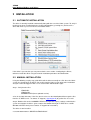
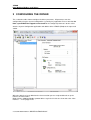
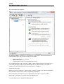
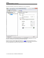
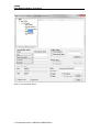
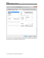
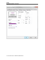
7TMOD
IGSS Modicon Modbus Serial Driver
User’s Manual
Seven Technologies
7-Technologies A/S * Bistruphave 3 * DK-3460 Birkerød * Denmark
Phone: +45 45 900 700 * Fax: +45 45 900 701 * CVR no. DK 73 63 41 13
E-mail: [email protected] World Wide Web: http://www.7t.dk
7TMOD
IGSS Modicon Modbus serial driver
DISCLAIMER
:
This is an unpublished work, the copyright of which vests in
SEVEN TECHNOLOGIES A/S.
All rights reserved.
The information contained herein is the property of SEVEN
TECHNOLOGIES and is supplied without liability for errors
or omissions.
No part may be reproduced or used except as authorised
by contract or other written permission.
The copyright and the foregoing restriction on reproduction
and use extend to all media in which the information may be
embodied.
X:\UKJ\WEB MIGRATION\PLC
DRIVERS\7TMOD.DOCX
7TMOD
IGSS Modicon Modbus serial driver
CONTENTS:
1
2
3
4
5
6
INTRODUCTION................................................................................................................. 3
1.1
Software Requirements .......................................................................................... 3
1.2
Hardware Requirements ........................................................................................ 3
INSTALLATION ................................................................................................................... 4
2.1
Automatic Installation ............................................................................................. 4
2.2
Manual Installation ................................................................................................. 4
CONFIGURING THE DRIVER ............................................................................................ 5
3.1
Adding a node ........................................................................................................ 9
3.2
Configuring the Objects ........................................................................................ 11
USE WITH MODEMS ....................................................................................................... 12
PERFORMANCE AND THROUGHPUT ........................................................................... 22
ERROR CODES ............................................................................................................... 23
X:\UKJ\WEB MIGRATION\PLC
DRIVERS\7TMOD.DOCX
7TMOD
IGSS Modicon Modbus serial driver
1 INTRODUCTION
This document describes how to set up and troubleshoot the IGSS 7TMOD Interface Driver.
The driver implements the Modicon Modbus protocol stack over modem/serial connection.
1.1 SOFTWARE REQUIREMENTS
None (see Hardware Requirements below).
The driver is designed to be used with IGSS version 7.0 and higher.
1.2 HARDWARE REQUIREMENTS
The driver requires a standard modem or serial connection for the IGSS pc and PLC, GSM
modems and serial devices like MOXA may be used.
Please refer to the manufacturers manual for PLC setup.
X:\UKJ\WEB MIGRATION\PLC
DRIVERS\7TMOD.DOCX
7TMOD
IGSS Modicon Modbus serial driver
2 INSTALLATION
2.1 AUTOMATIC INSTALLATION
The driver is normally installed automatically along with the rest of the IGSS system. To verify if
the driver has been installed open the System Configuration (sysconfig.exe) and check if a
driver with ID:81 is present in the list of available drivers:
If the driver is present then you can proceed to the next section: “Configuring the Driver”,
otherwise install the driver using the manual installation procedure described below.
2.2 MANUAL INSTALLATION
Using the following step-by-step guide will install the driver manually on a PC where the IGSS
system has already been installed. You need to stop the IGSS system prior to the installation
and you need to be logged in with a user account with “Administrator” rights.
Step 1: Verify that the files:
7TMOD.DLL
7TMODc.DLL
COMMDRV.REG (latest updated version)
exists in the GSS\ directory. If the files doesn’t exists run the IGSSUpdateClient to get the files
from the 7T WEB server – or contact 7T Support ([email protected]) to get the files via e-mail.
Step 2: Double-click on the COMMDRV.REG file to import the registry settings needed for the
system to recognize the driver. (please notice that double-clicking on a .REG file in a 64 Bit
Windows will NOT work, please contact 7T Support for instructions)
The driver is now installed.
X:\UKJ\WEB MIGRATION\PLC
DRIVERS\7TMOD.DOCX
7TMOD
IGSS Modicon Modbus serial driver
3 CONFIGURING THE DRIVER
This section describes how to configure the driver parameters. All parameters must be
configured by using the System Configuration (sysconfig.exe) application. Please note that the
IGSS system MUST be stopped and restarted for the configured parameters to take effect.
Start the System Configuration application and add the driver 7TMOD (ID:20) to the requested
station.
When the driver has been added to the relevant station you are ready to add and set up the
interface and PLC nodes.
Right-click the “Modicon Modbus protocol driver” tag in the left side tree view and select “New
Interface…” in the popup menu:
X:\UKJ\WEB MIGRATION\PLC
DRIVERS\7TMOD.DOCX
7TMOD
IGSS Modicon Modbus serial driver
The “Connection Type” appears.
The Modicon Modbus Serial driver is designed to use either direct serial communications or
modem/radio and thus you should select one of the options:
•
•
•
Connect directly via the serial port.
Modem connection.
Scheduled direct connect, radio modem for instance.
The “Connect directly via the serial port.” option is designed for permanent connection over a
serial cable, although using something like MOXA over an ethernet/internet connection is
supported as well. Both point-to-point and multi drop are supported .
Scheduled Connection:
Modem, one or more nodes are "connected" to a modem, the nodes are called at configurable
times to retrieve current values, alarms and possibly historic data.
Direct connection, basically the same as regular direct connection, except like modem
connections, connections are established at configurable time.
X:\UKJ\WEB MIGRATION\PLC
DRIVERS\7TMOD.DOCX
7TMOD
IGSS Modicon Modbus serial driver
For direct connections, permanent or scheduled, press the serial port tab.
The driver supports up to 8 serial ports in point-to-point or multi drop configurations. For each
port you must specify the communication parameters individually:
Each port must be configured with Serial port ID (e.g. \\.\COM1:) and serial port parameters.
Default serial parameters are 9600 Baud, 8 data bits, 1 stop bit and no parity. These parameters
must correspond with the parameters which you have set up in the sub stations.
X:\UKJ\WEB MIGRATION\PLC
DRIVERS\7TMOD.DOCX
7TMOD
IGSS Modicon Modbus serial driver
For modem connections
The driver supports using a dialed-up connection (PSTN or GSM). In this case the PC and each
substation must be equipped with a suitable PSTN or GSM modem. To configure one or more
modem connections you must select the option: “The PC and the PLC are connected via a
modem”:
Select the modem you want to use for the connection (in this case GVC 33.6K External.....
Modem) and continue to set up modem specific parameters by pressing the “Configure…”
button. The options available in the “Configure” popup dialog differs among modem vendors but
typically baud rate, flow control, additional AT modem commands, compression and other
hardware parameters can be set up using the “Configure…” dialog.
Technical note: The drivers modem interface uses Windows Telephone API (TAPI) which is a
standard component of the Windows OS system. Please make sure that you system has all
latest updates for TAPI installed.
Advice: Before deploying the driver it is advised that you test your modem connections manually
using a terminal program to make sure you have compatible modems and to verify that the
X:\UKJ\WEB MIGRATION\PLC
DRIVERS\7TMOD.DOCX
7TMOD
IGSS Modicon Modbus serial driver
modem commands that TAPI is using by default works with your modem.
Setting up a radio connection is exactly the same as setting up a serial port. Please refer to the
“DIRECT CONNECTION” section above.
3.1 ADDING A NODE
Right click the interface (modem or comport) in the left pane and choose New node in the
context menu.
You have now added your first node , Node 0.
Each PLC node requires a few fundamental parameters:
IGSS node number: This is the node number which IGSS uses to reference a unique PLC.
This node number is required when binding and IGSS atom (tag) to a register in the PLC. Any
number from the drop down list can be used.
Modbus Unit ID : This number corresponds to the Modbus ID of the PLC, please note that
X:\UKJ\WEB MIGRATION\PLC
DRIVERS\7TMOD.DOCX
7TMOD
IGSS Modicon Modbus serial driver
many Modbus PLCs won't respond if requests are sent using a wrong Modbus ID.
Processor type: Click this drop down box to select the PLC type (see screenshot above). STD
Modbus/GPRS are a generic Processor type and used in most cases, the rest is for specific
hardware.
X:\UKJ\WEB MIGRATION\PLC
DRIVERS\7TMOD.DOCX
7TMOD
IGSS Modicon Modbus serial driver
3.2 CONFIGURING THE OBJECTS
Once the driver and the PLC nodes have been defined, IGSS Objects and Atoms can be linked
to process variable in the PLC. Various different types of PLC memory can be accessed for
read/write operations using the driver.
By using the “Edit Mapping” tab in the object properties dialog you can specify the binding
between the object’s atoms and the PLC process variables. Start by selecting an atom and
select the 7TMOD driver in the “Driver” drop down list:
Now select the desired PLC node number and continue by setting be desired Device. Then
specify the number (register number within the device type). Note that the corresponding
Mnemonic is displayed and updated as you select the appropriate parameters. This is a help to
make sure you always bind to the correct process variable.
Continue this process for each atom on the object and save the parameters by clicking the OK
button when finished.
X:\UKJ\WEB MIGRATION\PLC
DRIVERS\7TMOD.DOCX
7TMOD
IGSS Modicon Modbus serial driver
4 USE WITH MODEMS
Using IGSS Modicon Modbus driver with a modem can be costly if not using with a flatrate line,
and it is suggested that you use Connection Scheduling and call your device at intervals to fetch
new data, this is especially true if your device support historic data.
In the “Connection Scheduling” section you can design a connection schedule either by entering
specific points in time during the day where the driver will establish connection or you can enter
a fixed time interval where the driver will establish connection – or a combination of both specific
points in time and fixed intervals.
Based on this schedule the driver will connect to the PLC and read all configured data points
(i.e. all the tags you have defined in that node). Once the driver have read all the data it will
disconnect until the next scheduled connection. Using this schedule dramatically reduces the
amount of data on the wire – but of course this comes at the price of not actually being
connected continuously.
In the “Connection hold time” section you might want to specify how long the driver should keep
X:\UKJ\WEB MIGRATION\PLC
DRIVERS\7TMOD.DOCX
7TMOD
IGSS Modicon Modbus serial driver
the connection “open” it either the user sends a command or if the user forces the driver to
establish a connection through a dialup/connection object.
The “Normal connect hold time” option allows you to define how many seconds the driver will
stay connected (online) if the user forces the driver to make a connection to the PLC. The “Send
cmd connect hold time” option allows you to specify how many seconds the driver will stay
online one the PLC node after the user has send a command. This latter is useful if the user
should be able to see the response of the command which he/she has just sent.
Once you are done defining the connection schedule continue to the “Connection Misc.” pane:
Since the driver is not continuously connected to the PLC you might want the PLC to store one
or historical data in designated areas in the PLC and let the driver fetch and timestamp these
data when it is online. If you e.g. want the driver to only be online each 4 hours but require
some important tags to be stored in the IGSS system each 5 minutes (e.g. for reporting or
trending) then you can use the “Collecting Historical Data” option to define where the data are
stored.
Click the “Settings” button to bring up the dialog used to define the layout of the historical data:
The dialog contains one row for each historical tag you want to define. The first 3 columns (Data
X:\UKJ\WEB MIGRATION\PLC
DRIVERS\7TMOD.DOCX
7TMOD
IGSS Modicon Modbus serial driver
Group, Word Offset, Word Length) contain the fields to define where and how the data will be
stored in IGSS. These parameters are used to bind the data to specific objects.
Data Group: This field should always be set to 0. This is a fixed value which is used by the
IGSS Modicon Modbus GPRS Driver to recognize that this is historical data. The value 512
maps to the Memory Type “Local Code0”.
Word Offset: This field id used to distinguish between the different historical data tags. It is
recommended to consequtive starting at 1 (one). The value of this field corresponds to the
“Word Offset” parameter in the “Edit Mapping” dialog when we bind the historical data to specific
objects. See details below.
Word Length: This parameter is used to tell the driver the size of each of the historical data
points. This should be set to 1 if the historical data is a 16 bit data type and it should be set to 2
if the historical data is a 32 bit data type.
Chan. Node: This parameter tells the driver which history channel it should access, it is only
available for some Processor Types, like the Grundfos CU361.
Technical note: IGSS requires time stamped data to ALWAYS come in a time synchronious
sequence with the oldest values first. This is automatically taken care of by the driver.
When binding the historical data series to IGSS objects you should set the “Memory Type” to
X:\UKJ\WEB MIGRATION\PLC
DRIVERS\7TMOD.DOCX
7TMOD
IGSS Modicon Modbus serial driver
“Local Code0” and then select a “Word Offset” which matched the “Word Offset” of one of the
historical data series you have just defined:
Make sure the I/O mode is set to “In”.
It is VERY IMPORTANT that you set the scan interval to “None” in the “Data Management
Definitions” pane. This is because that the scan interval doesn’t make sense for historical data
series and thus should be disabled by setting the “Scan interval” parameter to “None”:
X:\UKJ\WEB MIGRATION\PLC
DRIVERS\7TMOD.DOCX
7TMOD
IGSS Modicon Modbus serial driver
Since defining a connection schedule when using GPRS means that you are not online with the
PLC nodes continuously you might want to consider giving the user a possibility to manually
establish a connection to the PLC through the IGSS UI.
This is done by defining a “Connection Object” which allows the user to simply click a button on
the UI to control the connection. In the “Connection Misc.” pane you should first enable the
“Monitor and control connection” option in the “Connection Status and Control” group. When this
option is enabled you should enter 0 as Data Group and 0 as offset:
X:\UKJ\WEB MIGRATION\PLC
DRIVERS\7TMOD.DOCX
7TMOD
IGSS Modicon Modbus serial driver
In the IGSS definition module you should then create a new digital object based on the build-in
template called “DIALUP”:
X:\UKJ\WEB MIGRATION\PLC
DRIVERS\7TMOD.DOCX
7TMOD
IGSS Modicon Modbus serial driver
Set the scan interval to “None”:
X:\UKJ\WEB MIGRATION\PLC
DRIVERS\7TMOD.DOCX
7TMOD
IGSS Modicon Modbus serial driver
And bind both the Command- and the State atom to “Historical Data (Word)” and Word Offset 0
(this corresponds to parameters 0 and 0 we just set up in the “Connection Misc.” pane for the
driver).
X:\UKJ\WEB MIGRATION\PLC
DRIVERS\7TMOD.DOCX
7TMOD
IGSS Modicon Modbus serial driver
If you want to use e.g. a Command Field mimic to allow the user to control the connection state
to the PLC node then you could define something like this:
X:\UKJ\WEB MIGRATION\PLC
DRIVERS\7TMOD.DOCX
7TMOD
IGSS Modicon Modbus serial driver
X:\UKJ\WEB MIGRATION\PLC
DRIVERS\7TMOD.DOCX
7TMOD
IGSS Modicon Modbus serial driver
5 PERFORMANCE AND THROUGHPUT
The driver is designed for maximum throughput on a PSTN network. On a standard PC you
should expect a throughput of 5+ request/response cycles pr. minute depending on your
modem. To handle multiple PLCs concurrently you will need more than one modem.
IMPORTANT NOTICE: The IGSS communication engine optimizes communication throughput
by seeking to group data whenever possible. This means that if the communication engine is
required to read e.g. word offset 1 and word offset 31 then it will read data registers 1, 2,
through to word offset 31 as a block. This is much more efficient than reading the two data
registers using two separate read requests.
X:\UKJ\WEB MIGRATION\PLC
DRIVERS\7TMOD.DOCX
7TMOD
IGSS Modicon Modbus serial driver
6 ERROR CODES
This section describes the error codes specific to the IGSS 7TMOD interface driver.
While troubleshooting communication- or addressing problems the Driver Test Application might
be useful to display error codes reported by the driver.
0x1401 7TMOD_INVALID_POINTS
Cause: Read_Holding_Register response has an invalid number of points
Action: Check communication and PLC program
0x1402 7TMOD_INVALID_FUNCTION_CODE_RETURNED
Cause: The response from the PLC contained an invalid Function Code
Action: Check communication and PLC program
0x1403 7TMOD_INVALID_NODE_RETURNED
Cause: The returned Slave Address did not match the Node number
Action: Check subcode
Subcode: The wrong Slave Address returned from the PLC
0x1404 7TMOD_EXCEPTION_RESPONSE
Cause: The returned Function showed an Exception Response
Action: Check subcode
Subcode: Modbus Function Cose in high word, Modbus Exception Code in low word.
0x1405 7TMOD_CANT_SEND
Cause: Failed to write to COM port
Action: Verify Modem/Comport settings are correct
0x1406 7TMOD_CANT_RECV
Cause: Failed to receive from COM port
Action: Verify Modem/Comport settings are correct
0x1407 7TMOD_CLEARCOMERROR
Cause: Failed to clear COM port
Action: Verify Modem/Comport settings are correct
0x1408 7TMOD_RECV_LENGTH_ERROR1
Cause: More data received than defined in DriverSetup Segment size
Action: None, if the problem persists contact IGSS Support
0x1409 7TMOD_RECV_LENGTH_ERROR2
Cause: More data received than defined in DriverSetup Segment size
Action: None, if the problem persists contact IGSS Support
X:\UKJ\WEB MIGRATION\PLC
DRIVERS\7TMOD.DOCX