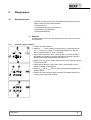
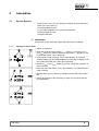
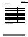
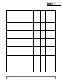
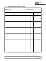
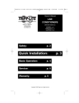
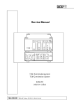
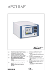
1
Service Manual Arthro Pump 2202 Zuständige Vertretung SM--2202 / Index: 09--98--1.0 / ÄM: TD 00--000 Wichtige allgemeine Anwendungshinweise Das Produkt nur bestimmungsgemäß und unter Beachtung der Gebrauchsanweisung, durch entsprechend ausgebildetes und qualifiziertes Fachpersonal einsetzen. Wartung und Reparatur nur durch autorisierte Fachkräfte. Das Produkt nur in den Kombinationen und mit dem Zubehör und den Ersatzteilen betreiben, die in der Gebrauchsanweisung angegeben sind. Andere Kombinationen, Zubehör und Verschleißteile nur dann verwenden, wenn diese ausdrücklich für die vorgesehene Anwendung bestimmt sind und Leistungsmerkmale sowie Sicherheitsanforderungen nicht beeinträchtigen. Die Produkte vor jeder Anwendung und Rücksendung zum Schutz von Patient, Anwender und Dritten, entsprechend der Gebrauchsanweisung aufbereiten. Technische Änderungen vorbehalten! Durch Weiterentwicklungen können Abbildungen und Technische Daten geringfügig abweichen. Struktur der Sicherheitshinweise Bildzeichen Klassifizierung der Gefährdung WARNUNG! Das Nichtbeachten kann zum Tod oder zu schwersten Verletzungen führen. VORSICHT! Das Nichtbeachten kann zu leichten Verletzungen oder zu Schäden am Produkt führen. . WICHTIG! . HINWEIS! Das Nichtbeachten kann zu Schäden am Produkt oder in der Umgebung führen. Anwendertips für eine optimale Gerätenutzung und sonstige nützliche Informationen. Important general instructions for use Ensure that this product is only used as intended and described in the instruction manual, by adequately trained and qualified personnel, and that maintenance and repair is only carried out by authorized specialized technicians. Operate this product only in the combinations and with the accessories and spare parts listed in the instruction manual. Use other combinations, accessories and wearing parts only if they are expressly intended for this use and if the performance and safety requirements are met. Reprocess the products before every application and before returning them for repair as required by the instruction manual in order to protect the patient, user or third parties. Subject to technical changes! Due to continuous development of our products, illustrations and technical data may deviate slightly from the data in this manual. CAUTION -- USA only: Federal law restricts this unit to be used or sold, except under the supervision of a medical doctor. Safety instructions and levels of danger Symbol Level of danger WARNING! Failure to observe can result in death or severe injury. CAUTION! Failure to observe can result in slight injury or damage to the product. . . 1 IMPORTANT! Failure to observe can result in damage to the product or surrounding. NOTE! Tips for optimum use and other useful information. SM--2202 DEUTSCH SM--2202 0 Inhalt 1 1.1 1.2 1.3 1.4 1.5 1.5.1 1.5.2 1.5.3 1.5.4 1.5.5 1.5.6 1.5.7 1.5.8 1.5.9 1.5.10 1.5.11 Wartung . . . . . . . . . . . . . . . . . . . . . . . . . . . . . . . . . . . . . . . . . . . . . . . . . . . . . . . . . . . . . . . . . Wichtige Hinweise . . . . . . . . . . . . . . . . . . . . . . . . . . . . . . . . . . . . . . . . . . . . . . . . . . . . . . . . . Wartung von Gerät und Zubehör . . . . . . . . . . . . . . . . . . . . . . . . . . . . . . . . . . . . . . . . . . . . . Sichtprüfung . . . . . . . . . . . . . . . . . . . . . . . . . . . . . . . . . . . . . . . . . . . . . . . . . . . . . . . . . . . . . . Elektrische Sicherheitsprüfung . . . . . . . . . . . . . . . . . . . . . . . . . . . . . . . . . . . . . . . . . . . . . . Funktionskontrolle . . . . . . . . . . . . . . . . . . . . . . . . . . . . . . . . . . . . . . . . . . . . . . . . . . . . . . . . . Einleitung . . . . . . . . . . . . . . . . . . . . . . . . . . . . . . . . . . . . . . . . . . . . . . . . . . . . . . . . . . . . . . . . Grundfunktionstest . . . . . . . . . . . . . . . . . . . . . . . . . . . . . . . . . . . . . . . . . . . . . . . . . . . . . . . . Drucksensoren . . . . . . . . . . . . . . . . . . . . . . . . . . . . . . . . . . . . . . . . . . . . . . . . . . . . . . . . . . . . Druckkammersitz . . . . . . . . . . . . . . . . . . . . . . . . . . . . . . . . . . . . . . . . . . . . . . . . . . . . . . . . . . Sicherheitfunktion bei Überdruck . . . . . . . . . . . . . . . . . . . . . . . . . . . . . . . . . . . . . . . . . . . . Geräteabschaltung bei Drehimpulsausfall . . . . . . . . . . . . . . . . . . . . . . . . . . . . . . . . . . . . . Druckdifferenz--Überwachung . . . . . . . . . . . . . . . . . . . . . . . . . . . . . . . . . . . . . . . . . . . . . . . Nullpunktkontrolle der Drucksensoren . . . . . . . . . . . . . . . . . . . . . . . . . . . . . . . . . . . . . . . . Überprüfung des Fußpedales . . . . . . . . . . . . . . . . . . . . . . . . . . . . . . . . . . . . . . . . . . . . . . . Überprüfung der automatischen Instrumentenerkennung . . . . . . . . . . . . . . . . . . . . . . . . Überprüfung der Kabelfernbedienung . . . . . . . . . . . . . . . . . . . . . . . . . . . . . . . . . . . . . . . . 1 1 1 2 2 3 3 3 3 4 4 4 4 5 5 5 5 2 2.1 2.1.1 2.1.2 2.1.3 2.1.4 2.1.5 2.2 2.3 2.3.1 2.3.2 2.3.3 2.3.4 2.3.5 2.3.6 2.3.7 2.3.8 2.3.9 Baugruppen . . . . . . . . . . . . . . . . . . . . . . . . . . . . . . . . . . . . . . . . . . . . . . . . . . . . . . . . . . . . . Serviceoptionen . . . . . . . . . . . . . . . . . . . . . . . . . . . . . . . . . . . . . . . . . . . . . . . . . . . . . . . . . . . Aufruf des Service--Menüs . . . . . . . . . . . . . . . . . . . . . . . . . . . . . . . . . . . . . . . . . . . . . . . . . . Druckmessung . . . . . . . . . . . . . . . . . . . . . . . . . . . . . . . . . . . . . . . . . . . . . . . . . . . . . . . . . . . . Endwertkalibrierung--Druckmessung . . . . . . . . . . . . . . . . . . . . . . . . . . . . . . . . . . . . . . . . . Offsetspannung des Motors . . . . . . . . . . . . . . . . . . . . . . . . . . . . . . . . . . . . . . . . . . . . . . . . . Drehzahlkalibrierung . . . . . . . . . . . . . . . . . . . . . . . . . . . . . . . . . . . . . . . . . . . . . . . . . . . . . . . Fehlermeldungen . . . . . . . . . . . . . . . . . . . . . . . . . . . . . . . . . . . . . . . . . . . . . . . . . . . . . . . . . . Baugruppentausch . . . . . . . . . . . . . . . . . . . . . . . . . . . . . . . . . . . . . . . . . . . . . . . . . . . . . . . . . Austausch der Netzversorgungskomponenten (Kaltgerätestecker) . . . . . . . . . . . . . . . Wechseln des Rollenrades . . . . . . . . . . . . . . . . . . . . . . . . . . . . . . . . . . . . . . . . . . . . . . . . . . Austausch des Motors . . . . . . . . . . . . . . . . . . . . . . . . . . . . . . . . . . . . . . . . . . . . . . . . . . . . . Austausch Bedienmodul . . . . . . . . . . . . . . . . . . . . . . . . . . . . . . . . . . . . . . . . . . . . . . . . . . . . Austausch Schaltnetzteil . . . . . . . . . . . . . . . . . . . . . . . . . . . . . . . . . . . . . . . . . . . . . . . . . . . Austausch Netzfilter . . . . . . . . . . . . . . . . . . . . . . . . . . . . . . . . . . . . . . . . . . . . . . . . . . . . . . . Austausch E--Karte UNI . . . . . . . . . . . . . . . . . . . . . . . . . . . . . . . . . . . . . . . . . . . . . . . . . . . . Austausch E--Karte KEY . . . . . . . . . . . . . . . . . . . . . . . . . . . . . . . . . . . . . . . . . . . . . . . . . . . . Austausch Mikroschalter . . . . . . . . . . . . . . . . . . . . . . . . . . . . . . . . . . . . . . . . . . . . . . . . . . . 6 6 6 7 7 7 7 8 9 9 9 9 10 10 10 10 11 11 3 3.1 3.2 3.2.1 3.3 3.3.1 3.4 3.5 Anhang / Annex . . . . . . . . . . . . . . . . . . . . . . . . . . . . . . . . . . . . . . . . . . . . . . . . . . . . . . . . . . Reparaturteile / Repair parts . . . . . . . . . . . . . . . . . . . . . . . . . . . . . . . . . . . . . . . . . . . . . . . . Explosionszeichnungen / Exploded view . . . . . . . . . . . . . . . . . . . . . . . . . . . . . . . . . . . . . . Legende / Legend . . . . . . . . . . . . . . . . . . . . . . . . . . . . . . . . . . . . . . . . . . . . . . . . . . . . . . . . . Funktionsschema / Operational Diagram . . . . . . . . . . . . . . . . . . . . . . . . . . . . . . . . . . . . . . Legende / Legend . . . . . . . . . . . . . . . . . . . . . . . . . . . . . . . . . . . . . . . . . . . . . . . . . . . . . . . . . Lageplän E--Karten / Component drawing PCB . . . . . . . . . . . . . . . . . . . . . . . . . . . . . . . . Blockschaltbild / Block Diagram . . . . . . . . . . . . . . . . . . . . . . . . . . . . . . . . . . . . . . . . . . . . . 12 12 13 13 14 14 15 16 4 4.1 4.2 Protokolle / Reports . . . . . . . . . . . . . . . . . . . . . . . . . . . . . . . . . . . . . . . . . . . . . . . . . . . . . . 17 Prüfprotokoll / Test Report . . . . . . . . . . . . . . . . . . . . . . . . . . . . . . . . . . . . . . . . . . . . . . . . . . 17 Wartungsprotokoll / Maintenance report . . . . . . . . . . . . . . . . . . . . . . . . . . . . . . . . . . . . . . 19 SM--2202 I 1 Wartung 1.1 Wichtige Hinweise Dieses Servicehandbuch beschreibt die für das Produkt festgelegten externen Servicemaßnahmen. . 1.2 WICHTIG! Zur Durchführung der Servicemaßnahmen, ist die Gebrauchsanweisung des Produktes unbedingt zu beachten. Wartung von Gerät und Zubehör Die Wartung und die Prüfung am Gerät soll zum Schutz des Prüfenden in der angegebenen Reihenfolge durchgeführt werden. Z Sichtprüfung Z Elektrische Sicherheitsprüfung Z Funktionskontrolle Die erforderlichen elektrischen Prüf--und Meßverfahren sind sind in den Normen EN 60601 / IEC 601 und DIN 57751 / VDE 751 beschrieben. Die im Abschnitt ”Sicherheitsprüfung” angegebenen Werte beziehen sich auf die Prüfung nach EN 60601 / IEC 601. Nach einer Reparatur müssen alle Meßwerte (Ausgangswerte) des Geräts anhand der Angaben in der Service Manual geprüft und bei Abweichungen neu eingestellt werden. . 1 HINWEIS! Alle Wartungs-- und Prüfarbeiten an Gerät oder Zubehör müssen dokumentiert werden. SM--2202 1.3 Sichtprüfung Die im OP--Raum angewandten Desinfektionsmittel sowie das beim Einsatz von UV--Strahlern freiwerdende Ozon, können die Oberflächen der Geräteteile verändern. Benennung Durchzuführende Kontrollen Gerät und Zubehör ' Sicherheitsgefährdende Verschmutzung und allgemeine Sauberkeit ' Mechanische Beschädigung ' Lose oder fehlende Teile Bedienelemente ' Mechanische Funktion und Freigängigkeit Frontplatte und Gehäuse ' Funktions-- und sicherheitsbeeinträchtigenden Beschädigungen ' Funktion der Bedienfelder und LED’s Rollenrad ' Einwandfreien Zustand, Sitz und Leichtgängigkeit Membranen und Abdeckungen ' Unbeschädigte Membranen der Drucksensoren ' Unbeschädigte Abdeckung der Druckkammerschalters Beschriftung / Symbolik ' Vollständig und gut lesbar Sicherheitsrelevante Aufschriften (z.B. Warnhinweise) ' Vollständig und gut lesbar Sicherungseinsätze ' Auf die vom Hersteller auf dem Typenschild angegebenen Werte (Nennstrom und Abschmelzcharakteristik) Verkabelung ' Auf einwandfreien Zustand (Sitz, Isolation und Brüchigkeit) E--Karten ' Korrosion oder andere Beschädigungen Lampenschild (Nur Lichtquellen) ' Vorhanden und gut lesbar ' Beschädigte Teile sofort austauschen! 1.4 Elektrische Sicherheitsprüfung Benennung Durchzuführende Kontrollen Schutzleiteranschluß Meßwerte: ' Ohne angeschlossener Versorgungsleitung ± 0,1 Ohm ' Mit angeschlossener Versorgungsleitung ± 0,2 Ohm Prüfbedingung: 10 A ± Imess ± 25 A , V0mess ± 6 V , tprüf ² 5 s Geprüft werden: Der Widerstand zwischen Schutzleiter, Schutzleiteranschluß und den damit verbundenen leitfähigen Teilen. Isolationswiderstand Meßwerte: ' Isolationswiderstand ² 2 MOhm Prüfbedingung: Prüfspannung 500V DC (Gleichspannung) Geprüft werden: Alle Netzleitungen gegen Erde. Ableitstrom Meßwerte: ' Geräteableitstrom ± 100 µA Prüfbedingung: Meßanordnung (MD) nach IEC 601 Geprüft werden: Der Ableitstrom, der von jedem Pol des Netzteils über die Isolierung durch den Schutzleiter oder vom Anwendungsteil über den Patienten zur Erde fließen kann. SM--2202 2 1.5 Funktionskontrolle 1.5.1 Einleitung Diese Einleitung soll Ihnen helfen, die Funktionalität des Gerätes besser zu verstehen, um so Bedien-- und Meßfehler zu vermeiden. 1.5.2 Grundfunktionstest Beim Grundfunktionstest werden die Anzeigen, die Tasten und die Förderleistung des Gerätes geprüft. Vorbereitung: Z Legen Sie das Schlauchset ein. Z Die Druckkammer muß hörbar einrasten. Z Verbinden Sie den Spülschlauch mit einem Flüssigkeitsbeutel. Der Flüssigkeitsbeutel muß 1,0 m über dem Gerät hängen. Z Legen Sie den Instrumentenschlauch in ein Meßgefäß hinein. Z Schalten Sie das Gerät am Netzschalter ein. Wählen Sie folgende Werte: Solldruck: 150 mm Hg Sollflow: 1.00 l/min Z Tippen Sie auf die Start/Stop--Taste. Die grüne Start/Stop--LED leuchtet. Das Rollenrad beginnt sich zu drehen. Z Füllen Sie das Schlauchset komplett mit Flüssigkeit und lassen Sie die Pumpe für 1 min laufen, um die automatische Instrumentenerkennung zu beenden. Z Klemmen Sie anschließend den Instrumentenschlauch ab. Tippen Sie nicht auf die Start/Stop--Taste. Durchführen: Z Entleeren Sie den Meßbecher. Z Lösen Sie die Abklemmung am Instrumentenschlauch und stoppen Sie 1 min. Z Nach Ablauf dieser Zeit drücken Sie die Start/Stop--Taste. Im Meßbecher müssen sich 1,0 l ( 10%) Wasser befinden. Beim Erreichen dieser Werte ist der Grundfunktionstest erfolgreich abgeschlossen. 1.5.3 Drucksensoren Z Schalten Sie das Gerät ein. Z Erzeugen Sie mit der Spitze nacheinander einen Druck von 50, 100 und 150 mm Hg. Z Die Werte zwischen Manometer und Istdruck--Anzeige dürfen mit einer Toleranz von 6 % abweichen. Im Fehlerfall muß das Gerät kalibriert werden (Kap. 2.1.2 ). Funktioniert das Gerät anschließend immer noch nicht einwandfrei, muß die E--Karte AM3--UNI ausgewechselt werden. 3 SM--2202 1.5.4 Druckkammersitz Z Überprüfen Sie mit dem Testschlauchset das Einlegen der Druckkammer in den Pumpenkopf. Z Die Druckkammer muß sich leicht einlegen lassen. Der Pumpenkopf und die Druckkammer müssen miteinander bündig abschließen. Im Fehlerfall muß die Baugruppe Bedienmodul ausgewechselt werden. 1.5.5 Sicherheitfunktion bei Überdruck Z Wählen Sie einen Solldruck von 150 mm Hg und einen Sollflow von 1,5 l/min. Z Betätigen Sie die Start/Stop Taste. Z Erzeugen Sie mit der Spitze einen Druck von mehr als 150 mm Hg (<250 mm Hg). Z Das Rollenrad muß sich rückwärts drehen. Z Nach ca. 5 s ertönt ein Warnton, der alle 5 s wiederholt wird. Z Tippen Sie erneut auf die Start/Stop Taste und entlasten Sie den Druck, um diesen Test zu beenden. Im Fehlerfall muß das Gerät kalibriert werden (Kap. 2.1.3 ). Funktioniert das Gerät anschließend immer noch nicht einwandfrei, muß die E--Karte AM3--UNI ausgewechselt werden. 1.5.6 Geräteabschaltung bei Drehimpulsausfall Z Wählen Sie einen Solldruck von 150 mm HG und einen Sollflow von 0,20 l/min. Z Betätigen Sie die Start/Stop Taste. Z Halten Sie das langsam drehende Rollenrad mit der Hand vorsichtig fest. Z Ein Warnton ertönt und in der Istdruck--Anzeige erscheint die Fehlermeldung ’E02’. Z Schalten Sie das Gerät aus. Im Fehlerfall muß das Gerät kalibriert werden (Kap. 2.1.5 ). Funktioniert das Gerät anschließend immer noch nicht einwandfrei, muß die E--Karte AM3--UNI ausgewechselt werden. 1.5.7 Druckdifferenz--Überwachung Z Entfernen Sie das Testschlauchset und schalten Sie das Gerät ein. Z Tippen Sie auf die Start/Stop Taste, um die Pumpe zu starten. Z Tippen Sie vorsichtig mit dem Finger auf einen Drucksensor. Z Die Fehlermeldung ’E01’ erscheint in der Istdruck--Anzeige und ein Warnton ertönt. Z Entlasten Sie den Drucksensor. Die Fehlermeldung erlischt. Z Wiederholen Sie den Test mit dem anderen Drucksensor. Z Schalten Sie das Gerät aus. Im Fehlerfall muß das Gerät kalibriert werden (Kap. 2.1.2 ). Funktioniert das Gerät anschließend immer noch nicht, muß die Baugruppe Bedienmodul und / oder die E--Karte AM3--UNI ausgewechselt werden. SM--2202 4 1.5.8 Nullpunktkontrolle der Drucksensoren Z Rufen Sie im Anwendermenü (Kap. 6) den Menüpunkt P2 auf. In P2 werden die gemessenen Werte der Drucksensoren in der Solldruck-und Istdruck--Anzeige dargestellt. DIese Werte müssen annähernd übereinstimmen ( 2 mm Hg). Z Schalten Sie das Gerät aus. Die Funktionsprüfung ist beendet. Im Fehlerfall muß das Gerät kalibriert werden (Kap. 2.1.3 ). Funktioniert das Gerät anschließend immer noch nicht, muß die Baugruppe Bedienmodul und / oder die E--Karte AM3--UNI ausgewechselt werden. 1.5.9 Überprüfung des Fußpedales Z Schalten Sie das Gerät ein. Z Schließen Sie den Flüssigkeitsbehälter und einen Schlauch mit LL an. Z Schließen Sie das Fußpedal an den Anschluß an der Geräterückwand an. Z Drücken Sie auf das Fußpedal. Die Sollflow--Anzeige springt auf ’1,50’ l/min und die Solldruck--Anzeige springt auf den im Anwendermenü vorgewählten Wert. Die Anzeige ’Fußpedal/Wash’ leuchtet. Z Drücken Sie erneut auf das Fußpedal und die Sollflow-- und Solldruck-Anzeige springen auf den zuletzt eingestellten Wert zurück. 1.5.10 Überprüfung der automatischen Instrumentenerkennung 2202.001 ab Serien--Nr. 98231 , 2202.011 ab Serien--Nr. 98100 Z Wählen Sie einen Solldruck von 100 mm Hg und einen Sollflow von 1,50 l/min. Tippen Sie auf die Start/Stop--Taste. Z Das Gerät erkennt automatisch das angeschlossene Instrument. Dabei kann das Rollenrad kurzfristig in verschiedenen Geschwindigkeiten laufen und mehrmals stoppen. Z Danach läuft das Rollenrad mit hoher Geschwindigkeit. Das Gerät erkennt, das kein Druck bzw. kein Instrument am Ende des Schlauches vorhanden ist. 1.5.11 Überprüfung der Kabelfernbedienung 2202.001 ab Serien--Nr. 98231 , 2202.011 ab Serien--Nr. 98100 Z Schließen Sie die Kabelfernbedienung an der Anschlußbuchse an der Vorderseite des Gerätes an. Z Mit der Fernbedienung sind alle Funktionen des Gerätes bedienbar. ' Druck: Erhöhen und Verringern des Solldruckes. ' Flow: Erhöhen und Verringern des Sollflows. ' Wash: Schnelles Verändern von Druck und Flow (Funktion ’Wash’). ' Start/Stop: Start/Stop der Insufflation. 5 SM--2202 2 Baugruppen 2.1 Serviceoptionen Über das Servicemenü können Sie Geräteparameter ändern und anzeigen lassen. Es gibt 4 Menüpunkte (L). L0 Druckmessung L1 Endwertkalibrierung--Druckmessung L2 Offsetspannung des Motors L3 Drehzahlkalibrierung . 2.1.1 WICHTIG! Die Menüpunkte nach einem Baugruppentausch auf jeden Fall noch einmal ausführen. Aufruf des Service--Menüs Z Schalten Sie das Gerät ein. Z Während ’-- -- --’ in der Istdruck--Anzeige blinkt (1), tippen Sie auf die pminus -- und auf pplus --Taste (2. Reihenfolge beachten!). In der Sollflow--Anzeige erscheint L1. Das ’L’ blinkt (3). Z Tippen Sie auf die Start / Stop --Taste (4). Das ’L’ hört auf zu blinken. Die Solldruck--Anzeige (5) (und ggf. die Istdruck--Anzeige) zeigt den aktuellen Parameter der aktivierten Menüebene an. Z Mit den pplus oder pminus Tasten (6) können Sie den Parameter der Menüebene verändern. Z Tippen Sie auf die Start / Stop--Taste. Das ’L’ blinkt wieder. Der gewählte Parameter ist gespeichert. Z Mit der Qplus oder Qminus Taste (7) kann eine andere Menüebene ausgewählt werden. Z Schalten Sie das Gerät aus. Nach erneutem Einschalten können Sie mit den neuen Parametern arbeiten. SM--2202 6 2.1.2 Druckmessung Z Für diesen Menüpunkt darf keine Druckkammer in den Pumpenkopf eingelegt sein. Z Wählen Sie die Menüebene L0. Z In der Solldruck-- und Istdruck--Anzeige werden die aktuellen Druckwerte der Drucksensoren angezeigt. Beide Anzeigen müssen den Wert ’115’ (2) anzeigen. Ist dies nicht der Fall, stellen Sie beide Anzeigen mit Hilfe der Potentiometer P1 und P2 auf der E--Karte AM3--UNI auf ’115’ (2) ein. Z Nach einer Neueinstellung der Nullpunkte müssen die Menüpunkte L1--L3 kalibriert werden. Z Tippen Sie auf die Start / Stop--Taste, um die Menüebene L0 zu verlassen. 2.1.3 Endwertkalibrierung--Druckmessung Z Legen Sie das Testschlauchset in den Pumpenkopf ein. Z Wählen Sie die Menüebene L1. Z Wählen Sie einen Solldruck von 200 mm Hg. Z Erzeugen Sie extern einen Druck von 200 mm Hg (267 mbar). Z Bringen Sie Solldruck-- und Istdruckanzeige zur Übereinstimmung. 0,5 Z Die Instrumentenanzeige zeigt einen Digitwert an. Z Bei Übereinstimmung der Werte, tippen Sie auf die Start / Stop--Taste, um die Menüebene L1 zu verlassen. 2.1.4 Offsetspannung des Motors Z Entfernen Sie das Testschlauchset. Z Wählen Sie die Menüebene L2. Z Das Gerät sucht selbstständig nach der Offsetspannung des Motors. Z Wenn das ’L’ in der Sollflow--Anzeige blinkt, ist die Überprüfung abgeschlossen. Sie können eine neue Menüebene wählen. 2.1.5 Drehzahlkalibrierung Z Legen Sie ein Orginalschlauchset in den Pumpenkopf ein. Dieser Test wird ohne Flüssigkeitsförderung durchgeführt. Z Wählen Sie die Menüebene L3. Z Das Rollenrad dreht sich. In der Solldruck--Anzeige wird die Umdreh-ungszahl pro Minute (U/min) angezeigt. Z Mit dem Potentiometer P3 auf der E--Karte AM3--UNI müssen 355 U/min (5) eingestellt werden. Z Dieser Menüpunkt kann nicht mit der Start / Stop--Taste verlassen werden. Schalten Sie das Gerät am Netzschalter aus. 7 SM--2202 2.2 Fehlermeldungen Fehler-- und Warnmeldungen Ursache Fehlerbehebung Warnanzeige ’Service’ leuchtet, ’E01’ erscheint in der Istdruck--Anzeige Warnton ertönt Die Druckdifferenz zwischen den Drucksensor ist größer als 50 mm Hg Kalibrieren Sie das Gerät (Kap. Servicemenü). Anschließend überprüfen Sie den Anwendermenüpunkt P2. Warnanzeige ’Service’ leuchtet, ’E02’ erscheint in der Istdruck--Anzeige, Warnton ertönt Die Motorsteuerung ist defekt. Kontrollieren Sie alle Zuleitungen zum Motor (Kabel locker u. a.). Warnanzeige ’Service’ leuchtet, ’E03’ erscheint in der Istdruck--Anzeige Das Gerät ist nicht kalibriert. Kalibrieren Sie das Gerät (Kap. Servicemenü). Warnanzeige ’Service’ leuchtet, ’E05’ erscheint in der Istdruck--Anzeige Fehler auf E--Karte AM3--UNI E--Karte AM3--UNI wechseln. Warnanzeige ’Service’ leuchtet, ’E07’ erscheint in der Istdruck--Anzeige Hardwarefehler auf der E--Karte AM3--KEY E--Karte AM3--KEY wechseln. Zwei kurze Warntöne hörbar Timeout--Fehler E--Karte AM3--UNI und AM3--KEY wechseln. Ein langer und ein kurzer Warnton hintereinander hörbar E--Karte AM3--KEY fehlerhaft E--Karte AM3--KEY wechseln. Anzeige dunkel E--Karte AM3--KEY fehlerhaft E--Karte AM3--KEY wechseln. Rollenrad dreht sich nicht Microschalter verklemmt oder Rollen am Rollenrad nicht leicht gängig Microschalter oder Rollenrad wechseln. Zwei kurze Warntöne hintereinander hörbar Interner Datenfehler E--Karte AM3--UNI wechseln. VORSICHT! Für das Modell 2202.001 ab Serien- Nr. 98231 und 2202.011 ab Serien- Nr. 98100 wird eine neue Key- Karte verwendet. SM--2202 8 2.3 Baugruppentausch 2.3.1 Austausch der Netzversorgungskomponenten (Kaltgerätestecker) Z Die Netzversorgungskomponenten bestehen aus Kaltgerätestecker, Plastikabdeckung und Kabel. Z Stellen Sie sicher, daß das Gerät vom Netz getrennt ist. Entfernen Sie das Netzkabel aus der Gerätesteckdose. Z Lösen Sie die Befestigungen und Kabel der Netzversorgung. Z Nach Einbau der neuen Netzversorgung müssen folgende Tests durchgeführt werden: ' Elektrische Sicherheitstests 2.3.2 Wechseln des Rollenrades Z Stellen Sie sicher, daß das Gerät vom Netz getrennt ist. Entfernen Sie das Netzkabel aus der Gerätesteckdose. Z Drehen Sie das Rollenrad mit der Hand so lange, bis der Gewindestift nach oben zeigt. Lösen Sie den Gewindestift. Z Ziehen Sie das Rollenrad von der Achse herunter und ersetzen Sie es durch ein neues. Z Befestigen Sie das Rollenrad nachdem SIe sicher gestellt haben, daß die Flachstelle der Achse in die Richtung des Gewindestiftes zeigt. Überrprüfen Sie nach dem Festziehen, ob das Rollenrad mit dem Einschnitt im Pumpenkopf fluchtet. Ist das nicht der Fall, müssen Sie das Rollenrad neu justieren. Z Nach Einbau des neuen Rollenrades müssen folgende Tests durchgeführt werden: ' Elektrische Sicherheitstests 2.3.3 Austausch des Motors Z Stellen Sie sicher, daß das Gerät vom Netz getrennt ist. Entfernen Sie das Netzkabel aus der Gerätesteckdose. Z Entfernen Sie das Rollenrad wie im Punkt 2.3.2 beschrieben. Z Lösen Sie die Befestigungen und Kabel des Motors. Z Nach Einbau des neuen Motors müssen folgende Tests durchgeführt werden: ' Elektrische Sicherheitstests ' Servicemenü ' Funktionsprüfung 9 SM--2202 2.3.4 Austausch Bedienmodul Z Das Bedienmodul besteht aus Designfolie, Frontplatte, Pumpenkopf-oberteil und Pumpenkopfunterteil und ist nur komplett montiert erhältlich Z Stellen Sie sicher, daß das Gerät vom Netz getrennt ist. Entfernen Sie das Netzkabel aus der Gerätesteckdose. Z Entfernen Sie Netzschalter, Rollenrad mit Motor und Mircroschalter. Z Lösen Sie die Befestigungen und Kabel des Bedienmoduls. Z Nach Einbau des neuen Bedienmoduls müssen folgende Tests durchgeführt werden: ' Elektrische Sicherheitstests ' Servicemenü ' Funktionsprüfung 2.3.5 Austausch Schaltnetzteil Z Stellen Sie sicher, daß das Gerät vom Netz getrennt ist. Entfernen Sie das Netzkabel aus der Gerätesteckdose. Z Entfernen Sie die Abdeckung des Schaltnetzteils. Z Lösen Sie die Befestigungen und Kabel der Netzversorgung. Z Nach Einbau des neuen Schaltnetzteils müssen folgende Tests durchgeführt werden: ' Elektrische Sicherheitstests 2.3.6 Austausch Netzfilter Z Stellen Sie sicher, daß das Gerät vom Netz getrennt ist. Entfernen Sie das Netzkabel aus der Gerätesteckdose. Z Lösen Sie die Befestigungen und Kabel der Netzfilters. Z Nach Einbau des neuen Netzfilters müssen folgende Tests durchgeführt werden: ' Elektrische Sicherheitstests 2.3.7 Austausch E--Karte UNI Z Stellen Sie sicher, daß das Gerät vom Netz getrennt ist. Entfernen Sie das Netzkabel aus der Gerätesteckdose. Z Lösen Sie die Befestigungen und Kabel der E--Karte. Z Nach Einbau der neuen E--Karte müssen folgende Tests durchgeführt werden: ' Elektrische Sicherheitstests ' Servicemenü ' Funktionsprüfung SM--2202 10 2.3.8 Austausch E--Karte KEY Z Stellen Sie sicher, daß das Gerät vom Netz getrennt ist. Entfernen Sie das Netzkabel aus der Gerätesteckdose. Z Lösen Sie die Befestigungen und Kabel der E--Karte. Z Nach Einbau der neuen E--Karte müssen folgende Tests durchgeführt werden: ' Elektrische Sicherheitstests ' Servicemenü ' Funktionsprüfung 2.3.9 Austausch Mikroschalter Z Stellen Sie sicher, daß das Gerät vom Netz getrennt ist. Entfernen Sie das Netzkabel aus der Gerätesteckdose. Z Lösen Sie die Befestigungen und Kabel des Microschalters. Z Nach Einbau des neuen Microschalters müssen folgende Tests durchgeführt werden: ' Elektrische Sicherheitstests ' Funktionsprüfung 11 SM--2202 ENGLISH SM--2202 0 Contents 1 1.1 1.2 1.3 1.4 1.5 1.5.1 1.5.2 1.5.3 1.5.4 1.5.5 1.5.6 1.5.7 1.5.8 1.5.9 1.5.10 1.5.11 Maintenance . . . . . . . . . . . . . . . . . . . . . . . . . . . . . . . . . . . . . . . . . . . . . . . . . . . . . . . . . . . . . . Important notes . . . . . . . . . . . . . . . . . . . . . . . . . . . . . . . . . . . . . . . . . . . . . . . . . . . . . . . . . . . . Maintenance of device and accessories . . . . . . . . . . . . . . . . . . . . . . . . . . . . . . . . . . . . . . . Visual check . . . . . . . . . . . . . . . . . . . . . . . . . . . . . . . . . . . . . . . . . . . . . . . . . . . . . . . . . . . . . . . Electrical safety check . . . . . . . . . . . . . . . . . . . . . . . . . . . . . . . . . . . . . . . . . . . . . . . . . . . . . . Functional Check . . . . . . . . . . . . . . . . . . . . . . . . . . . . . . . . . . . . . . . . . . . . . . . . . . . . . . . . . . . Introduction . . . . . . . . . . . . . . . . . . . . . . . . . . . . . . . . . . . . . . . . . . . . . . . . . . . . . . . . . . . . . . . . Basic Functional Test . . . . . . . . . . . . . . . . . . . . . . . . . . . . . . . . . . . . . . . . . . . . . . . . . . . . . . . Pressure sensors . . . . . . . . . . . . . . . . . . . . . . . . . . . . . . . . . . . . . . . . . . . . . . . . . . . . . . . . . . . Seating of Pressure Chamber . . . . . . . . . . . . . . . . . . . . . . . . . . . . . . . . . . . . . . . . . . . . . . . . Safety function in case of overpressure . . . . . . . . . . . . . . . . . . . . . . . . . . . . . . . . . . . . . . . . Device shut--down in case of failure to detect rotary pulse . . . . . . . . . . . . . . . . . . . . . . . . Pressure Differential Monitoring . . . . . . . . . . . . . . . . . . . . . . . . . . . . . . . . . . . . . . . . . . . . . . Checking the Pressure Sensor Zero Point . . . . . . . . . . . . . . . . . . . . . . . . . . . . . . . . . . . . . Checking the Pedal Switch . . . . . . . . . . . . . . . . . . . . . . . . . . . . . . . . . . . . . . . . . . . . . . . . . . . Checking Automatic Instrument Recognition . . . . . . . . . . . . . . . . . . . . . . . . . . . . . . . . . . . Checking the cable remote control . . . . . . . . . . . . . . . . . . . . . . . . . . . . . . . . . . . . . . . . . . . . 1 1 1 2 2 3 3 3 3 4 4 4 4 5 5 5 5 2 2.1 2.1.1 2.1.2 2.1.3 2.1.4 2.1.5 2.2 2.3 2.3.1 2.3.2 2.3.3 2.3.4 2.3.5 2.3.6 2.3.7 2.3.8 2.3.9 Assemblies . . . . . . . . . . . . . . . . . . . . . . . . . . . . . . . . . . . . . . . . . . . . . . . . . . . . . . . . . . . . . . . Service Options . . . . . . . . . . . . . . . . . . . . . . . . . . . . . . . . . . . . . . . . . . . . . . . . . . . . . . . . . . . . Calling the service menu . . . . . . . . . . . . . . . . . . . . . . . . . . . . . . . . . . . . . . . . . . . . . . . . . . . . Pressure Measurement . . . . . . . . . . . . . . . . . . . . . . . . . . . . . . . . . . . . . . . . . . . . . . . . . . . . . Limit Value Calibration -- Pressure Measurement . . . . . . . . . . . . . . . . . . . . . . . . . . . . . . . . Offset Voltage of Motor . . . . . . . . . . . . . . . . . . . . . . . . . . . . . . . . . . . . . . . . . . . . . . . . . . . . . . Speed Calibration . . . . . . . . . . . . . . . . . . . . . . . . . . . . . . . . . . . . . . . . . . . . . . . . . . . . . . . . . . Error Messages . . . . . . . . . . . . . . . . . . . . . . . . . . . . . . . . . . . . . . . . . . . . . . . . . . . . . . . . . . . . Replacing Assemblies . . . . . . . . . . . . . . . . . . . . . . . . . . . . . . . . . . . . . . . . . . . . . . . . . . . . . . . Replacing the Power Supply Components (panel--mounted 3--pole power plug) . . . . . Replacing the Pump Wheel . . . . . . . . . . . . . . . . . . . . . . . . . . . . . . . . . . . . . . . . . . . . . . . . . . Replacing the Motor . . . . . . . . . . . . . . . . . . . . . . . . . . . . . . . . . . . . . . . . . . . . . . . . . . . . . . . . Replacing the Control Module . . . . . . . . . . . . . . . . . . . . . . . . . . . . . . . . . . . . . . . . . . . . . . . . Replacing the Switching Power Supply . . . . . . . . . . . . . . . . . . . . . . . . . . . . . . . . . . . . . . . . Replacing the Line Filter . . . . . . . . . . . . . . . . . . . . . . . . . . . . . . . . . . . . . . . . . . . . . . . . . . . . . Replacing the UNI PCB . . . . . . . . . . . . . . . . . . . . . . . . . . . . . . . . . . . . . . . . . . . . . . . . . . . . . Replacing the KEY PCB . . . . . . . . . . . . . . . . . . . . . . . . . . . . . . . . . . . . . . . . . . . . . . . . . . . . . Replacing the microswitch . . . . . . . . . . . . . . . . . . . . . . . . . . . . . . . . . . . . . . . . . . . . . . . . . . . 6 6 6 7 7 7 7 8 9 9 9 9 10 10 10 10 11 11 3 3.1 3.2 3.2.1 3.3 3.3.1 3.4 3.5 Anhang / Annex . . . . . . . . . . . . . . . . . . . . . . . . . . . . . . . . . . . . . . . . . . . . . . . . . . . . . . . . . . . Reparaturteile / Repair parts . . . . . . . . . . . . . . . . . . . . . . . . . . . . . . . . . . . . . . . . . . . . . . . . . Explosionszeichnungen / Exploded view . . . . . . . . . . . . . . . . . . . . . . . . . . . . . . . . . . . . . . . Legende / Legend . . . . . . . . . . . . . . . . . . . . . . . . . . . . . . . . . . . . . . . . . . . . . . . . . . . . . . . . . . Funktionsschema / Operational Diagram . . . . . . . . . . . . . . . . . . . . . . . . . . . . . . . . . . . . . . . Legende / Legend . . . . . . . . . . . . . . . . . . . . . . . . . . . . . . . . . . . . . . . . . . . . . . . . . . . . . . . . . . Lageplän E--Karten / Component drawing PCB . . . . . . . . . . . . . . . . . . . . . . . . . . . . . . . . . Blockschaltbild / Block Diagram . . . . . . . . . . . . . . . . . . . . . . . . . . . . . . . . . . . . . . . . . . . . . . 12 12 13 13 14 14 15 16 4 4.1 4.2 Protokolle / Reports . . . . . . . . . . . . . . . . . . . . . . . . . . . . . . . . . . . . . . . . . . . . . . . . . . . . . . . 17 Prüfprotokoll / Test Report . . . . . . . . . . . . . . . . . . . . . . . . . . . . . . . . . . . . . . . . . . . . . . . . . . . 17 Wartungsprotokoll / Maintenance report . . . . . . . . . . . . . . . . . . . . . . . . . . . . . . . . . . . . . . . 19 SM--2202 I 1 Maintenance 1.1 Important notes This service manual describes the external service measures defined for the product. . 1.2 IMPORTANT! Follow the instruction manual of the product when carrying out the service measures. Maintenance of device and accessories In order to protect the person performing the test, carry out maintenance and checking or testing must be carried out in the order specified below. Z Visual check Z Electrical safety check Z Functional check The required electrical checking and measuring procedures are described in standards EN 60601 / IEC 601 and DIN 57751 / VDE 751. The values indicated under the section entitled safety check relate to the test to EN 60601 / IEC 601. After a repair job all measuring values (specified values) of the device must be checked in accordance with the instructions given in the Service Manual and readjusted if deviations are observed. . 1 NOTE! Any maintenance, checking or testing work on the device or the accessories must be documented. SM--2202 1.3 Visual check The disinfectants used in the operating theatre as well as the ozone freed when UV radiation sources are used, may change the surfaces of device parts. Item to be checked Check for Device and accessories ' Any soiling/contamination jeopadizing safety and general cleanliness ' Mechanical damage ' Loose or missing parts Controls ' Mechanical function and easy operation Front plate and housing ' Any damage having an effect on function and safety ' Function of control panels and LEDs Roller wheel ' Perfect condition, correct seating and easy operation Membranes and covers ' Undamaged membranes of pressure sensors ' Undamaged cover of pressure chamber switch Labeling / Symbols ' Completeness and good legibility Safety--relevant inscriptions (such as warnings) ' Completeness and good legibility Fuse inserts ' Values indicated by the manufacturer on the identification plate (nominal current and melting characteristics) Cabling ' Perfect condition (position, insulation and possible brittleness) Printed circuit boards ' Corrosion or other damage Lamp plate (only light sources) ' Existence and good legibility ' Replace damaged parts immediately! 1.4 Electrical safety check Item to be checked Check for Protective earth (PE) connection Measurement values: ' With supply cable not connected ± 0.1 Ohm ' With supply cable connected ± 0.2 Ohm Test conditions: 10 A ± Imeas ± 25 A , V0meas ± 6 V , ttest ² 5 s Check: The resistance between protective earth (PE) wire, protective earth (PE) connection and the conductive parts connected. Insulation resistance Measurement values: ' Insulation resistance² 2 MOhm Test conditions: Test voltage 500V DC (continuous voltage) Check: All mains (power) cables relative to earth. Leakage current Measurement values: ' Device leakage current ± 100 µA Test conditions: Measuring setup (MD) in accordance with IEC 601 Check: The leakage current which flows from each pole of the power supply unit via the insulation through the protective earth (PE) wire or from the application part via the patient to earth. SM--2202 2 1.5 Functional Check 1.5.1 Introduction This introduction should help you to better understand the functionality of this device in order to avoid operator’s errors and measuring errors. 1.5.2 Basic Functional Test In the basic functional test the indicators, pushbuttons and the delivery rate of the device are checked. Preparation: Z Install the flexible tube set. Z The pressure chamber must click into place. Z Connect the irrigation tube to the fluid bag. The fluid bag must be suspended 1.0 m above the device. Z Place the instrument tube into a measuring vessel. Z Switch on the device with the mains/power switch. Select the following values: Nominal Pressure: 150 mm Hg Nominal Flow: 1.00 l/min Z Press the start/stop button. The green start/stop LED lights up. The pump wheel starts rotating. Z Fill the entire tube set with liquid and let the pump run for 1 min. to complete automatic instrument recognition. Z Then cross--clamp the instrument tube. Do not press the start/stop button. Carry out the following: Z Empty the measuring vessel. Z Remove the cross clamp from the instrument tube and time 1 min. Z After 1 min press the start/stop button. The measuring vessel must the contain 1.0 l ( 10%) water. If you obtain these values the basic functional test has been successfully completed. 1.5.3 Pressure sensors Z Switch on the device. Z Use a syringe to generate pressures of 50, 100 and 150 mm Hg(mercury column). Z The values of the pressure gauge and the actual pressure reading may deviate with a tolerance of 6 % . In the case of a wrong reading the device needs calibration (Chapter 2.1.2 ). If the device won’t work properly after calibration, replace the AM3--UNI PCB. 3 SM--2202 1.5.4 Seating of Pressure Chamber Z Use the flexible test tube set to check the installation of the pressure chamber in the pump head. Z The pressure chamber must be easy to install. The pump head and the pressure chamber must be flush relative to each other. In the case of malfunction replace the control module assembly. 1.5.5 Safety function in case of overpressure Z Select a nominal pressure of 150 mm Hg and a nominal flow of 1.5 l/min. Z Actuate the start/stop button. Z Use a syringe to generate a pressure of more than 150 mm Hg (<250 mm Hg). Z The pump wheel must turn backwards. Z After approx. 5 s a warning is sounded that is repeated every 5 s. Z Press the start/stop button again and release the pressure in order to complete this test. In the case of malfunction the device needs calibration (Chapter 2.1.3 ). If the device still won’t work after this, replace the AM3--UNI PCB. 1.5.6 Device shut--down in case of failure to detect rotary pulse Z Select a nominal pressure of 150 mm HG and a nominal flow of 0.20 l/min. Z Actuate the start/stop button. Z Carefully hold the pump wheel with your hand while it is rotating slowly. Z A warning signal is sounded and an error message ’E02’ appears on the nominal pressure display. Z Switch off the device. In the case of malfunction the device needs calibration (Chapter 2.1.5 ). If the device won’t work properly after this, replace the AM3--UNI PCB. a 1.5.7 Pressure Differential Monitoring Z Remove the flexible tube set and switch on the device. Z Press the start/stop button to start the pump. Z Carefully tap a pressure sensor with your finger. Z Error message ’E01’ is displayed on the actual pressure indicator and a warning signal is sounded Z Release the pressure sensor. The error message disappears. Z Repeat the test with a different pressure sensor. Z Switch off the device. In the case of failure the device requires calibration (Chapter 2.1.2 ). If the device won’t work after this, replace the control module assembly and/or the AM3--UNI PCB. SM--2202 4 1.5.8 Checking the Pressure Sensor Zero Point Z Call menu item P2 in the user menu (Chapter 6). In P2 the values measured by the pressure sensors are displayed on the nominal pressure and acutal pressure displays. These values must be approximately the same ( 2 mm Hg). Z Switch off the device. This completes the function test. In the case of malfunction the device requires calibration (Chapter 2.1.3 ). If the device won’t work after that, the control module assembly and/or the AM3 UNI PCB must be replaced. 1.5.9 Checking the Pedal Switch Z Switch on the device. Z Connect the fluid container and a flexible tube with LL. Z Connect the pedal switch to the corresponding connector on the rear pannel of the device. Z Press the pedal swith. The nominal flow indicator will read ’1.50’ l/min and the nominal pressure indicator will display the value preselected in the User Manual. The ’Pedal switch/Wash’ indicator lights up. Z Press the pedal switch again and the nominal flow and nominal pressure readings will return to the previous value. 1.5.10 Checking Automatic Instrument Recognition 2202.001 as of serial number 98231, 2202.011 as of serial number 98100 Z Select a nominal pressure of 100 mm Hg (MC) and a nominal flow of 1.50 l/min. Touch the start/stop button. Z The device will automatically recognize the connected instrument. During this procedure the pump wheel may run briefly at various speeds and may stop several times. Z After this the pump wheel will run at high speed. The device detects the lack of pressure, i.e. that no instrument is connected to the end of the tube. 1.5.11 Checking the cable remote control 2202.001 as of serial number 98231, 2202.011 as of serial number 98100 Z Connect the cable remote control to the connecting socket on the front pannel of the device. Z The remote control can be used to control all functions of the device. ' Pressure: Increasing and decreasing of the nominal pressure. ' Flow: Increasing and decreasing of the nominal flow. ' Wash: Quick change of pressure and flow (’Wash’ function). ' Start/stop: Starting /Stopping insufflation. 5 SM--2202 2 Assemblies 2.1 Service Options Via the service menu you can change and display device parameters. There are 4 menu items (L). L0 Pressure Measurement L1 Limit value calibration for pressure measurement L2 Offset voltage of motor L3 Speed calibration . 2.1.1 IMPORTANT! Always perform the menu items again after replacing an assembly. Calling the service menu Z Switch on the device. Z While the actual pressure reading ’-- -- --’ blinks (1), touch the pminus -and pplus buttons (2. Observe actuation sequence!). L1 appears on the nominal flow display. The ’L’ blinks (3). Z Push the start / stop button (4). The ’L’ stops blinking. The nominal pressure display (5) (and if applicable the actual pressure display) read the current parameter of the menu level activated. Z With the pplus or the pminus button (6) you can change the parameter of the menu level. Z Press the start / stop button. The ’L’ starts blinking. The selected parameter is stored. Z With the Qplus or Qminus button (7) a different menu level can be selected. Z Switch off the device. After switching on again you may work with the new parameters. SM--2202 6 2.1.2 Pressure Measurement Z For this menu item the pressure chamber must not be in the pump head. Z Select menu level L0. Z The nominal pressure and actual pressure displays read the current pressure values detected by the pressure sensors. The two readings must be ’115’ (2). If this is not the case, adjust the two readings to ’115’ (2) by means of potentiometers P1 and P2 on the AM3--UNI PCB. Z After readjustment of the zero points calibrate menu items L1 -- L3. Z Press the start / stop button to exit menu level L0. 2.1.3 Limit Value Calibration -- Pressure Measurement Z Place the flexible test tube set into the pump head. Z Select menu level L1. Z Select a nominal pressure of 200 mm Hg (MC). Z Generate a pressure of 200 mm Hg (267 mbar) externally. 0.5 Z Adjust the nominal pressure and actual pressure readings to the same value. Z The instrument display reads a digital value. Z If the values are the same, press the start / stop button in order to exit menu level L1. 2.1.4 Offset Voltage of Motor Z Remove the flexible test tube set. Z Select menu level L2. Z The device will automatically look for the motor offset voltage. Z When the ’L’ in the nominal flow display blinks, the check is completed. You may now select a new menu level. 2.1.5 Speed Calibration Z Place a genuine tubing set into the pump head. This test will be performed without fluid delivery. Z Select menu level L3. Z The pump roller wheel turns. The nominal pressure display reads the rotations per minute (rpm). Z Potentiometer P3 on the AM3--UNI PCB must be adjusted in such a way that a speed of 355 rpm (5) is acchieved. Z This menu item cannot be exited by means of the start / stop button. Switch off the device with the mains/power switch. 7 SM--2202 2.2 Error Messages Error Messages and Warnings Cause Corrective Action Service warning lights, ’E01’ appears on the actual pressure display A warning signal is sounded The pressure differential between the pressure sensors is greater than 50 mm Hg (Mc) Calibrate the device (Chapter on Service menu). Then check the user menu item P2. Service warning lights, ’E02’ appears in the actual pressure display, A warning signal is sounded The motor control circuit is defective. Check all supply cables to the motor (loose cable etc.). Service warning lights, ’E03’ appears on the actual pressure display The device is not calibrated. Calibrate the device (Chapter on Service menu). Service warning lights, ’E05’ appears on the actual pressure display Error on AM3--UNI PCB Replace AM3--UNI PCB. Service warning lights , ’E07’ appears on the actual pressure display Hardware error on the AM3--KEY PCB Replace AM3--KEY PCB. Two short warning signals are sounded Timeout error Replace AM3--UNI and AM3--KEY PCBs. A long and a short warning signal are sounded consecutively The AM3--KEY is defective. Replace AM3--KEY PCB. Display is dark AM3--KEY PCB defective Replace AM3--KEY PCB. Pump wheel is stopped Microswitch jammed or rollers on pump wheel do not turn easily Replace microswitch or pump wheel. Two short warning signals are sounded consecutevely Internal data error Replace AM3--UNI PCB. CAUTION! For Model 2202.001 as of Serial Nr. 98231 and 2202.011 as of Serial Nr. 98100 a new key card is used. SM--2202 8 2.3 Replacing Assemblies 2.3.1 Replacing the Power Supply Components (panel--mounted 3--pole power plug) Z The power supply components consist of the panel--mounted 3--pole power plug, plastic cover and cable. Z Make sure that the device is disconnected from the power supply (mains). Disconnect the power cable from the device. Z Disconnect the screws and cables from the power supply unit. Z After having installed a new power supply unit perform the following tests: ' Electrical safety tests 2.3.2 Replacing the Pump Wheel Z Make sure that the device is disconnected from the power supply (mains). Disconnect the power cable from the device. Z Turn the pump wheel by hand until the grub screw faces upward. Loosen the grub screw. Z Pull the pump wheel off the shaft and install a new one. Z Tighten the grub screw insuring that it rests against the flat surface provided on the shaft. After tightening the grub screw check the pump wheel for proper alignment with the pump head. If it is not properly aligned, realign the pump wheel. Z After installing the new pump wheel perform the following tests: ' Electrical safety tests 2.3.3 Replacing the Motor Z Make sure that the device is disconnected from the power supply (mains) Disconnect the power cable from the device. Z Remove the pump wheel as described under item 6.3.2. Z Unscrew the mounting screws and disconnect the cables from the motor. Z After having installed the new motor perform the following tests: ' Electrical safety tests ' Service menu ' Functional check 9 SM--2202 2.3.4 Replacing the Control Module Z The control module consists of the design foil, front panel, upper part of pump head and lower part of pump head and is only available as a pre--assembled unit. Z Make sure that the device is disconnected from the power supply (mains). Disconnect the power cable from the device. Z Remove the power swith, pump (roller) wheel with motor and micro switch. Z Unscrew the mounting screws and disconnect the cables of the control module. Z After installation of the new control module perform the following tests: ' Electrical safety tests ' Service menu ' Functional check 2.3.5 Replacing the Switching Power Supply Z Make sure that the device is disconnected from the power supply (mains). Disconnect the power cable from the device. Z Remove the cover of the switching power supply. Z Unscrew the mounting screws and disconnect the power supply cables. Z After installation of a new switching power supply perform the following tests: ' Electrical safety tests 2.3.6 Replacing the Line Filter Z Make sure that the device is disconnected from the power supply (mains). Disconnect the power cable from the device. Z Unscrew the mounting screws and disconntect cables from the line filter. Z After having installed the new line filter, perform the following tests: ' Electrical safety tests 2.3.7 Replacing the UNI PCB Z Make sure that the device is disconnected from the power supply (mains). Disconnect the power cable from the device. Z Unscrew the mounting screws and disconnect the cables from the PCB. Z After installation of the new PCB perform the following tests: ' Electrical safety tests ' Service menu ' Functional check SM--2202 10 2.3.8 Replacing the KEY PCB Z Make sure that the device is disconnected from the power supply (mains). Disconnect the cable from the device. Z Unscrew the mounting screws and disconnect the cables from the PCB. Z After having installed the new PCB perform the following tests: ' Electrical safety tests ' Service menu ' Functional check 2.3.9 Replacing the microswitch Z Make sure that the device is disconnected from the power supply (mains). Disconnect the power cable from the device. Z Unscrew the mounting screws and cables from the microswitch. Z After having installed the new microswitch perform the following tests: ' Electrical safety tests ' Functional check 11 SM--2202 3 Anhang / Annex 3.1 Reparaturteile / Repair parts Pos. Type / Model Bezeichnung Designation 0010 64 210.020 Frontrahmen Front frame HM 2 0020 72 316.201 Wippenschalter 2WIXII/6138 GR Main switch 0030 64 330.032 Kunststoffuß Foot of the device 0040 64 330.033 Etikett ”NEXT CHECK” Label ”NEXT CHECK” 0050 64 330.034 Etikett ”Prüfplakette lfd. Jahr” Label ”date for next service” 0060 64 330.031 Verpackung surgiline recyclable Packing surgiline recyclable 0070 2440.501 Sicherung T 5,0 L 250 V Fuse T 5,0 L 250 V 0080 64 330.000 Gehäuseoberteil Top of the device 0090 64 330.035 Frontplatte /AM3 Front plate 0100 64 330.036 Designfolie /AM3 Design foil 0110 64 330.037 Netzversorgungskomponenten kpl. 0120 64 330.005 Pot. Ausgleich MC--Steck. US+Farbsch. Equipotent. MC--Plug US+COD. DISK 0130 64 330.038 E--Karte AM3 KEY gelb rev. 1.0 PC board AM3 KEY yel. rev. 1.0 0140 64 330.039 Schlauchanschluß 4--3,5 für Fußsch. Tube connection 4--3,5 for foot pedal 0150 64 330.020 Schaltnetzteil kpl. Switching power supply, cpl. 0160 64 330.040 Abdeckung für Netzteil Cover for switching power supply 0170 64 330.041 Motor für kleine Pumpen kpl. Motor for small pumps cpl. 0180 64 330.008 Mikroschalter kpl Microswitch cpl. 0190 64 330.042 Schutzabdeckung für Mikroschalter Protective cov. f. micro switch 0200 64 330.009 Rollenrad kpl. HM3 Roller wheel cpl. HM3 0210 64 330.043 E--Karte AM3 UNI rev. 1.0 PC board AM3 0220 64 330.044 Montagematerial /AM3 Mountig set Power supply components cpl. rev. 1.0 ' Positionsnummern siehe Explosionszeichnung ' For position numbers see exploded view SM--2202 12 3.2 Explosionszeichnungen / Exploded view 1 2 3 4 18 5 17 16 6 7 8 9 15 10 14 11 13 3.2.1 1 2 3 4 5 6 7 8 9 10 11 12 13 14 15 16 17 18 12 Legende / Legend Gehäuseoberteil Schaltnetzteil Abdeckung f. Schaltnetzteil Netzfilter Schlauchanschluß Fußschalter Potentialausgleichsstecker Netzversorgungskomponenten E--Karte AM3 UNI rev. 1.0 Gehäuseunterteil Mikroschalter , Schutzabdeckung Frontplatte Pumpenkopf, Oberteil Pumpenkopf, Unterteil Rollenrad Netzschalter E--Karte AM3 KEY rev. 1.0 grün Frontplattenträger Pumpenmotor 13 1 2 3 4 5 6 7 8 9 10 11 12 13 14 15 16 17 18 Top of housing Switching power supply Cover for switching power supply Line filter Tube connector for footswitch Equipotential connector Power supply components AM3 UNI PCB rev. 1.0 Bottom of housing Microswitch, protective cover Front panel Pump head, top Pump head, bottom Pump wheel Power (mains) switch AM3 KEY PCB rev. 1.0 green Front panel carrier Pump motor SM--2202 3.3 Funktionsschema / Operational Diagram 3.3.1 Legende / Legend 1 Pumpenmotor 1 Pump Motor 2 Drehzahlmesser 2 Speed Counter 3 Pumpenkopf 3 Pump Head 4 Fußschalter/Fernbedienung 4 Foot Switch / Remote control 5 Start / Stop--Taste 5 Start / Stop--Button 6 Lautsprecher 6 Speaker 7 Anzeigen 7 Display 8 Tastatur 8 Keyboard 9 Netzschalter 9 Power Switch SM--2202 14 3.4 Lageplän E--Karten / Component drawing PCB E--Karte AM3--KEY rev. 1.0 / AM3--KEY PCB rev. 1.0 E--Karte AM3--UNI rev. 1.0 / AM3--UNI PCB rev. 1.0 15 SM--2202 3.5 Blockschaltbild / Block Diagram data bus amplifier AD converter address bus pressure pick--up and pre--processing Increments overpressure and differential pressure shut--down /overpressure microcontroller /overpressure /motor enable display and keyboard overpressure safety logic overpressure safety shut--down SM--2202 motor control circuit and motor safety shut--down 16 4 Protokolle / Reports 4.1 Prüfprotokoll / Test Report Betreiber / User: ..................................................................... Typen Nr. / Type No.: .............................. Anschrift / Address: ................................................................................................................................... Durchgeführte Prüfung Test carried out 17 Serien Nr. Serial No. Datum Date Name / Unterschrift Name / Signature SM--2202 Durchgeführte Prüfung Test carried out SM--2202 Serien Nr. Serial No. Datum Date Name / Unterschrift Name / Signature 18 4.2 Wartungsprotokoll / Maintenance report Betreiber / User: .................................................................... Typen Nr. / Type No.: .............................. Anschrift / Address: ................................................................................................................................. Wartungsmaßnahmen Servicing check up 19 Serien Nr. Serial No. Datum Date Name / Unterschrift Name / Signature SM--2202 Wartungsmaßnahmen Servicing check up SM--2202 Serien Nr. Serial No. Datum Date Name / Unterschrift Name / Signature 20 GERMANY RICHARD WOLF GmbH D--75438 Knittlingen Pforzheimerstr. 32 Tel.: (..49)--(0)7043--35--0 Fax: (..49)--(0)7043--35300 MANUFACTURER E--mail: Internet: [email protected] www.richard--wolf.com USA RICHARD WOLF Medical Instruments Corp. 353 Corporate Woods Parkway Vernon Hills, Illinois 60061 Tel.: 847--913 1113 Fax: 847--913 1488 E--mail: sales&[email protected] Internet: www.richardwolfusa.com UK RICHARD WOLF UK Ltd. Waterside Way Wimbledon SW 17 0HB Tel.: 020--8944 7447 Fax: 020--8944 1311 E--mail: [email protected] Internet: www.richardwolf.uk.com BELGIUM N.V. Endoscopie RICHARD WOLF Belgium S.A. Industriezone Drongen Landegemstraat 6 B--9031 Gent --Drongen Tel.: +32 9.280.81.00 Fax: +32 9.282.92.16 E--mail: [email protected] FRANCE RICHARD WOLF France S.A.R.L. Rue Daniel Berger Z.A.C. La Neuvillette F--51100 Reims Tel.: +33 3.26.87.02.89 Fax: +33 3.26.87.60.33 E--mail: [email protected] AUSTRIA RICHARD WOLF Austria Ges.m.b.H. Wilhelminenstraße 93 a A--1160 Wien Tel.: +43 1-- 405 51 51 Fax: +43 1-- 405 51 51--45 E--mail: [email protected] Internet: www.richard--wolf.at 21 SM--2202