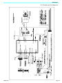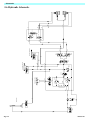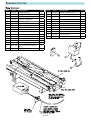
1
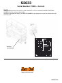
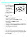
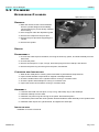
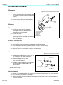
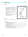
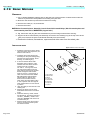
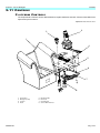
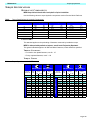
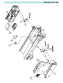
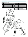
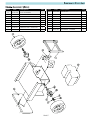
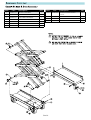
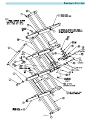
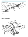
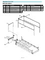
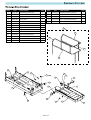
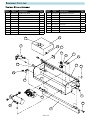
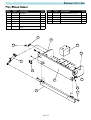
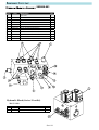
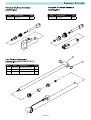
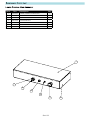
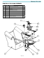
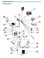
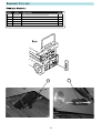
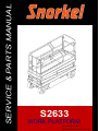
SERVICE & PARTS MANUAL
S2633
WORK PLATFORM
Serial Number 51089
Manual Serial Number 500422-103
S2633
Serial Number 51089 – Current
English
When contacting Snorkel for service or parts information, be sure to include the MODEL and SERIAL
NUMBER from the equipment Nameplate.
Should the nameplate be missing, the SERIAL NUMBER is also stamped on top of the chassis above the
front axle pivot.
Stamped
Serial Number
www.snorkelusa.com
508244-103
Section 3
S ER VICE
AND
R EPAIR
I NTRODUCTION
This section contains instructions for the maintenance of the Work Platform.
Refer to the General Information section for information relevant to all Snorkel work platforms.
Referring to the Operator Manual will aid in understanding the operation and function of the various components and systems of the work platform, and help in diagnosing and repair of the machine.
!
W A R N I N G
!
Be sure to read, understand and follow all information in the Operation Section of this manual before
attempting to operate or perform service on any Work Platform.
!
D A N G E R
!
Never perform service on the work platform in the elevating assembly area while platform is elevated
without first blocking the elevating assembly.
DO NOT stand in elevating assembly area while deploying or storing brace.
508244-103
Page 3-1
Section 3 - Service & Repair
TABLE OF C ONTENTS
3-1 Supporting Elevating Assembly . . . . . . . . . . . . . . . . . . . . . . . . . . . . . . . . . . . . . . . . . . . . . . . . . . . 3-3
Installation . . . . . . . . . . . . . . . . . . . . . . . . . . . . . . . . . . . . . . . . . . . . . . . . . . . . . . . . . . . . . . . . . . . . 3-3
Removal . . . . . . . . . . . . . . . . . . . . . . . . . . . . . . . . . . . . . . . . . . . . . . . . . . . . . . . . . . . . . . . . . . . . . . 3-3
3-2 Preventative Maintenance . . . . . . . . . . . . . . . . . . . . . . . . . . . . . . . . . . . . . . . . . . . . . . . . . . . . . . . . 3-3
3-3 Preventative Maintenance Check List . . . . . . . . . . . . . . . . . . . . . . . . . . . . . . . . . . . . . . . . . . . . . . 3-4
3-4 Parts Location . . . . . . . . . . . . . . . . . . . . . . . . . . . . . . . . . . . . . . . . . . . . . . . . . . . . . . . . . . . . . . . . . 3-5
3-5 General Lubrication . . . . . . . . . . . . . . . . . . . . . . . . . . . . . . . . . . . . . . . . . . . . . . . . . . . . . . . . . . . . . 3-6
3-6 Batteries . . . . . . . . . . . . . . . . . . . . . . . . . . . . . . . . . . . . . . . . . . . . . . . . . . . . . . . . . . . . . . . . . . . . . . 3-6
Battery Maintenance . . . . . . . . . . . . . . . . . . . . . . . . . . . . . . . . . . . . . . . . . . . . . . . . . . . . . . . . . . . . 3-7
Battery Replacement . . . . . . . . . . . . . . . . . . . . . . . . . . . . . . . . . . . . . . . . . . . . . . . . . . . . . . . . . . . . 3-7
3-7 Safety Ancillary Equipment . . . . . . . . . . . . . . . . . . . . . . . . . . . . . . . . . . . . . . . . . . . . . . . . . . . . . . . 3-8
Proximity Switch . . . . . . . . . . . . . . . . . . . . . . . . . . . . . . . . . . . . . . . . . . . . . . . . . . . . . . . . . . . . . . . . 3-8
Tilt Sensor . . . . . . . . . . . . . . . . . . . . . . . . . . . . . . . . . . . . . . . . . . . . . . . . . . . . . . . . . . . . . . . . . . . . 3-8
Emergency Lowering . . . . . . . . . . . . . . . . . . . . . . . . . . . . . . . . . . . . . . . . . . . . . . . . . . . . . . . . . . . . 3-8
3-8 Hydraulics . . . . . . . . . . . . . . . . . . . . . . . . . . . . . . . . . . . . . . . . . . . . . . . . . . . . . . . . . . . . . . . . . . . . . 3-9
Hydraulic Oil Tank And Filter . . . . . . . . . . . . . . . . . . . . . . . . . . . . . . . . . . . . . . . . . . . . . . . . . . . . . . 3-9
Hydraulic Pump . . . . . . . . . . . . . . . . . . . . . . . . . . . . . . . . . . . . . . . . . . . . . . . . . . . . . . . . . . . . . . . 3-10
Main Hydraulic Manifold . . . . . . . . . . . . . . . . . . . . . . . . . . . . . . . . . . . . . . . . . . . . . . . . . . . . . . . . . 3-11
Setting Hydraulic Manifold Pressures . . . . . . . . . . . . . . . . . . . . . . . . . . . . . . . . . . . . . . . . . . . . . . 3-12
3-9 Cylinders . . . . . . . . . . . . . . . . . . . . . . . . . . . . . . . . . . . . . . . . . . . . . . . . . . . . . . . . . . . . . . . . . . . . . 3-13
Depression Cylinder . . . . . . . . . . . . . . . . . . . . . . . . . . . . . . . . . . . . . . . . . . . . . . . . . . . . . . . . . . . . 3-13
Steering Cylinder . . . . . . . . . . . . . . . . . . . . . . . . . . . . . . . . . . . . . . . . . . . . . . . . . . . . . . . . . . . . . . 3-14
Lift Cylinder . . . . . . . . . . . . . . . . . . . . . . . . . . . . . . . . . . . . . . . . . . . . . . . . . . . . . . . . . . . . . . . . . . 3-15
3-10 Drive Motors . . . . . . . . . . . . . . . . . . . . . . . . . . . . . . . . . . . . . . . . . . . . . . . . . . . . . . . . . . . . . . . . . . 3-16
Removal . . . . . . . . . . . . . . . . . . . . . . . . . . . . . . . . . . . . . . . . . . . . . . . . . . . . . . . . . . . . . . . . . . . . . 3-16
Installation . . . . . . . . . . . . . . . . . . . . . . . . . . . . . . . . . . . . . . . . . . . . . . . . . . . . . . . . . . . . . . . . . . . 3-16
3-11 Controls. . . . . . . . . . . . . . . . . . . . . . . . . . . . . . . . . . . . . . . . . . . . . . . . . . . . . . . . . . . . . . . . . . . . . . 3-17
Platform Controls . . . . . . . . . . . . . . . . . . . . . . . . . . . . . . . . . . . . . . . . . . . . . . . . . . . . . . . . . . . . . . 3-17
Chassis Controls . . . . . . . . . . . . . . . . . . . . . . . . . . . . . . . . . . . . . . . . . . . . . . . . . . . . . . . . . . . . . . 3-18
Page 3-2
508244-103
Section 3 - Service & Repair
Supporting Elevating Assembly
3-1 S UPPORTING E LEVATING A SSEMBLY
!
W A R N I N G
!
Never perform service on the work platform in the elevating assembly area while platform is elevated
without first blocking the elevating assembly.
DO NOT stand in elevating assembly area while deploying or storing brace.
Figure 3-1: Elevating Assembly Brace
INSTALLATION
1. Park the machine on a firm, level surface.
2. Pull Chassis Emergency Stop Switch to the ON
position.
3. Pull Platform Emergency Stop Switch to the ON
position.
4. Turn and hold the Chassis Key Switch to CHASSIS.
5. Push the Chassis Lift/Lower Switch to LIFT to elevate
the platform until the maintenance brace can be
rotated to the vertical position.
6. From the rear of the machine, lift the maintenance
brace from its stowed position. Rotate upward and
outward, then down until it is hanging vertically below
its attachment point.
7. Lower the platform by pushing the Chassis Lift/Lower
Switch to LOWER and gradually lower the platform
until the maintenance brace is supporting the platform.
REMOVAL
1. Using the Chassis Controls, gradually elevate the
platform until the maintenance brace is clear.
2. Rotate the maintenance brace outward and upward over its attachment point until it rests in the
stowed position.
3. Lower the platform by pushing the Chassis Lift/Lower Switch to LOWER to completely lower the
platform.
3-2 P REVENTATIVE M AINTENANCE
The complete inspection consists of periodic visual and operational checks, along with periodic minor
adjustments to assure proper performance. Daily inspection will prevent abnormal wear and prolong the
life of all systems. The inspection and maintenance schedule is to be performed at regular intervals.
Inspection and maintenance shall be performed by personnel who are trained and familiar with mechanical
and electrical procedures.
!
W A R N I N G
!
Before performing preventative maintenance, familiarize yourself with the operation of the machine.
Always block the elevating assembly whenever it is necessary to enter the scissor assembly to perform
maintenance while the platform is elevated.
The preventative maintenance table has been designed for machine service and maintenance repair.
Please copy the following page and use the table as a checklist when inspecting the machine for service.
508244-103
Page 3-3
Preventative Maintenance Check List
Section 3 - Service & Repair
3-3 P REVENTATIVE M AINTENANCE C HECK L IST
PREVENTATIVE MAINTENANCE KEY
PREVENTATIVE MAINTENANCE REPORT
Interval
Date: _______________________________________
Daily=each shift or every day
Owner:______________________________________
50h/30d=every 50 hours or 30 days
250h/6m=every 250 hours or 6 months
Model No: ___________________________________
1000h/2y=every 1000 hours or 2 years
Serial No: ___________________________________
Y=Yes/Acceptable
N=No/Not Acceptable
Serviced By: _________________________________
R=Repaired/Acceptable
COMPONENT
INSPECTION OR SERVICES
Check electrolyte level
Check battery cable condition
Charge batteries
Battery
Check charger condition &
System operation
Check specific gravity
Clean exterior
Clean terminals
Check oil level
Hydraulic
Change Filter
Oil*
Drain and replace oil
Check for leaks
Hydraulic
Check hose connections
System
Check hoses for exterior wear
Drive Motors Check for operation and leaks
Emergency Check procedure for
Down
Emergency Down
Check for fitting leaks
Wipe clean
Hydraulic Check for leaks at mating
Pump
surfaces
Check mounting bolts for proper
torque
Controller Check condition & operation
Check fasteners for proper
torque
Platform Check welds for cracks
Deck & Rails
Check condition of deck
Check entry way closure
Service Interval: ______________________________
INTERVAL
Daily
Daily
Daily
Daily
6m
6m
6m
Daily
6m
2y
Daily
30d
30d
Daily
Daily
Daily
30d
30d
6m
Daily
Daily
Daily
Daily
Daily
Y
N
R
COMPONENT
INSPECTION OR SERVICES
Inspect for external damage,
dents, loose rivets or cracks
Elevating Check welds for cracks
Assembly Lubricate
Check cables for pinch or
rubbing points
Chassis Check welds for cracks
Check component mounting for
proper torque
Check for leaks
Lift Cylinder
Check for proper torque
Perform pre-operation
inspection
Check for and repair collision
damage
Entire Unit
Lubricate
Check fasteners for proper
torque
Check for corrosion; remove
and repaint
Check for peeling, missing, or
Labels
unreadable labels & replace
Wheels Check for loose components
Oil pivot pins
Oil king pins
Check steering cylinder for
Steering leaks
System Check hardware & fittings for
proper torque
Check Wheel Yoke Securing
Bolt and Nut
INTERVAL
Y
N
R
Daily
Daily
30d
Daily
Daily
6m
Daily
6m
Daily
Daily
30d
6m
6m
Daily
Daily
30d
30d
30d
6m
30d
* NOTE: Use ISO #46 during summer and ISO #32 during winter.
Page 3-4
508244-103
Section 3 - Service & Repair
Parts Location
3-4 P ARTS L OCATION
Figure 3-2: Parts Location
1. Entry Gate
2. Deck Lock Assembly
3. Work Platform
4. Fold Down Guardrails
5. Platform Extension
6. Platform Controls
7. Rear Guardrail Retaining Pin
8. Guardrail Retaining Pin
9. Elevating Assembly
10. Control Module
11. Chassis Controls
12. Circuit Board
13. Motor Controller
14. Hydraulic Fluid Reservoir
15. Hydraulic Fluid Filter
16. Hydraulic Pump and Motor
17. Main Valve Manifold
18. 175 AMP Fuse, Overload
Protection
19. Solenoid, Motor Relay
20. Audible Alarm
21. Depression Mechanism
22. Depression Mechanism
Cylinder
23. Battery Charger Plug
24. Battery Charger
25. Battery Pack
26. Cable Connector
27. Power Module
28. Drive Motors
29. Steering Cylinder
30. Lift Cylinder
31. Maintenance Brace
32. Level Sensor
33. Proximity Switch
34. Height Limit Switch
35. Series Parallel Valve
36. Emergency Lowering Valve
37. Emergency Lowering Valve
Knob
38. Horn
508244-103
Page 3-5
General Lubrication
Section 3 - Service & Repair
3-5 G ENERAL L UBRICATION
NOTE: Apply grease to each grease fitting
Figure 3-3: Steering
Lubrication Points.
There are four lubrication points on the machine steering
system - two on each steering pivot (see Figure).
Lubricate the steering pivots every 125 hours or three
months.
1. Deploy the maintenance brace (see “Blocking the
Elevating Assembly”).
2. Clean the grease fittings and surrounding area.
3. Using multipurpose grease in a grease gun, pump the
grease into the fitting until grease just begins to
appear at the edges of the pivot.
4. Wipe off any excess grease.
Figure 3-4: Lift Ram & Scissor Pin Lubrication Points
3-6 B ATTERIES
The batteries are located in a slide-out tray in the rear of the machine. Electrical Energy for the motor is
supplied by four 6 volt batteries wired in series for 24 volts DC. Correct care and maintenance of the batteries and motor will ensure maximum performance from the work platform.
C A U T I O N
If battery water level is not maintained, batteries will not fully charge, creating a low discharge rate.
!
W A R N I N G
!
Hazard of explosive gas mixture. Keep sparks, flame and smoking materials away from batteries.
Always wear safety glasses when working with batteries.
Battery fluid is highly corrosive. Thoroughly rinse away any spilled fluid with clean water.
Always replace batteries with Snorkel batteries or manufacturer approved replacements.
Before disconnecting the battery negative (-) lead, make sure all switches are OFF. If ON, a spark will
occur at the ground terminal which could cause an explosion if hydrogen gas or fuel vapors are
present.
Page 3-6
508244-103
Section 3 - Service & Repair
Batteries
BATTER Y MAINTENANCE
Refer to the Operation Manual included in this Service Manual for specific maintenance and
charging instructions.
NOTE: If system voltage drops below 17 volts (on a 24 volt system), the charger will not recharge the batteries. If this
extreme voltage drop occurs, disconnect and recharge each battery separately using a 6 volt charger to bring the
voltage in each up to at least 4 1/2 volts.
BATTERY REPLACEMENT
Battery cables must be installed as shown in the Battery Cable Installation Diagram.
Figure 3-5: Battery Cable Installation Diagram
1. Turn the Chassis Key Switch to the OFF position and
push the Chassis and Platform Emergency Stop
Switches down to the OFF position.
NOTE: If switches are ON, a spark will occur at the ground
terminal which could cause an explosion if hydrogen
gas or fuel vapors are present.
2. Open the power module.
3. Disconnect battery pack connector.
4. Disconnect the battery negative (–) lead.
IMPORTANT: Disconnect the battery negative (–) lead first.
5. Disconnect the remaining battery leads.
6. Lift the batteries out of the module.
Batteries Installed
INSTALLATION
IMPORTANT: Connect the battery negative (–) lead last.
1. Verify that the Chassis Key Switch and the Chassis and Platform Emergency Stop Switches are in the
OFF position.
2. Place the batteries into the power module.
3. Connect the battery to battery leads.
4. Connect the battery positive (+) lead.
5. Connect the battery negative (–) lead.
6. Connect the battery pack connector.
508244-103
Page 3-7
Safety Ancillary Equipment
Section 3 - Service & Repair
3-7 S AFETY A NCILLARY E QUIPMENT
PROXIMITY SWITCH
Figure 3-6: Proximity Switch
The Proximity Switch cuts power to the High Speed
Drive when the platform is elevated.
The switch is located on the left side of the chassis at
the rear of the machine.
No adjustment of the switch should be necessary.
LEVEL SENSOR
Figure 3-7: Level Sensor
The Level Sensor is located on the chassis
of the machine
These units are sealed and pre-set and
require no recalibration or adjustment.
EMERGENCY LOWERING
!
W A R N I N G
!
If the platform should fail to lower, NEVER climb down the elevating assembly.
Stand clear of the elevating assembly while operating the Emergency Lowering Valve Knob.
Figure 3-8: Emergency Lowering Knob
The Emergency Lowering Valve is mounted on the base of the lift
cylinder. The cable is routed;
• from the valve,
• along the elevating assembly tube to the front of the machine,
• through the cable access hole to the rear of the machine.
REPAIR
1. Deploy the maintenance brace (see “Blocking the Elevating
Assembly”).
Emergency Lowering Knob
2. Inspect the cable. Replace if damaged.
3. Inspect the valve. Replace if damaged.
4. Check for and clear any blockage in the orifice. Install the orifice with the beveled side toward the
cylinder block.
5. Adjust the valve. At the cable mount, adjust the cable cover to stop the inner cable when the valve is
fully open.
6. Store the maintenance brace and lower the platform.
Page 3-8
508244-103
Section 3 - Service & Repair
Hydraulics
3-8 H YDRAULICS
H Y D R A U L I C O I L TA N K
AND
FILTER
FLUID LEVEL
Figure 3-9: Hydraulic Tank
Check the fluid level daily.
With the platform fully lowered, open the control
module and remove the reservoir breather/cap.
Fluid should be at the full mark.
NOTE: Drain plug underneath tank
OIL
AND
FILTER REPLACEMENT
Replace the filter every 250 hours or six months.
1. Unscrew the filter from the filter assembly.
2. Apply a thin film of clean hydraulic fluid to the
gasket of the replacement filter.
Filler Cap
3. Screw the replacement filter onto the filter head until gasket makes contact then turn filter ¾ of a turn.
!
C A U T I O N
!
The hydraulic oil may be of sufficient temperature to cause burns. Wear safety gloves and safety
glasses when handling hot oil.
FLUID REPLACEMENT
Replace the hydraulic fluid every 1000 hours or two years.
1. Operate the machine for 10-15 minutes to bring the hydraulic fluid up to normal operating
temperature.
2. Provide a suitable container to catch the drained fluid.
• Hydraulic reservoir capacity: 15 L (4 U.S. gal).
3. Open the control module door.
4. Remove the drain plug and allow all the fluid to drain. Dispose of hydraulic fluid properly (contact your
local fluid recycler).
5. Install the drain plug.
6. Fill the hydraulic reservoir with the appropriate hydraulic fluid until the fluid is up to the full mark on the
dipstick.
• Refer to “Specifications” at the end of the Operator Manual included in this Service Manual to identify
the proper fluid for your conditions.
FLUID OUTLET SCREEN
Clean or replace the outlet screen at the same time that the fluid is changed.
1. Drain the fluid (see “Fluid Replacement”).
2. Disconnect and plug the outlet hose to prevent foreign material from entering the hose.
3. Remove the suction screen. Clean or replace as necessary.
4. Install the suction screen.
5. Fill the hydraulic reservoir (see “Fluid Replacement”).
508244-103
Page 3-9
Hydraulics
Section 3 - Service & Repair
HYDRAULIC PUMP
The Hydraulic Pump is located in the Power Module, and is mounted on the rear of the motor.
REMOVAL
NOTE: If the hydraulic tank has not been drained, suitable means for plugging the hoses should be provided to prevent
excessive fluid loss.
1. Mark, disconnect and plug the hose assemblies.
2. Loosen the capscrews and remove the pump assembly from the motor.
INSTALLATION
Figure 3-10: Hydraulic Pump Assembly
1. Lubricate the pump shaft with general
purpose grease and attach the pump
to the motor with the capscrews.
2. Using a crisscross pattern, torque
each capscrew a little at a time until
all capscrews are torqued to 27N-m
(20 ft-lbs).
3. Unplug and reconnect the hydraulic
hoses.
4. Check the oil level in the hydraulic
tank before operating the work
platform.
1. Inlet Hose
2. Outlet Hose
3. Capscrew
Page 3-10
4. Pump Assembly
5. Electric Motor
508244-103
Section 3 - Service & Repair
Hydraulics
MAIN HYDRAULIC MANIFOLD
Though it is not necessary to remove the manifold to perform all maintenance procedures, a determination
should be made prior to beginning as to whether or not the manifold should be removed before maintenance procedures begin.
Figure 3-11: Valve Location
1 TEST PORT1
7 VALVE, SOLENOID (DRIVE/LIFT)
2 FITTING, 1/4” - 1/4” MALE/MALE
8 PRESSURE RELIEF (MAIN LIFT)
3 FITTING, 3/8” - 3/8” MALE/MALE
9 VALVE, SOLENOID (STEERING)
4 FITTING, 1/2” - 1/2” (MALE/MALE)
10 FLOW RESTRICTOR (STEERING)
5 CROSS LINE RELIEF VALVE (DRIVE)
11 RELIEF VALVE (STEERING)
6 VALVE, SOLENOID (DRIVE)
12 RELIEF VALVE (MAIN RELIEF)
Figure 3-12:
SETTING HYDRAULIC MANIFOLD PRESSURES
!
W A R N I N G
!
The hydraulic oil may be of sufficient temperature to cause burns. Wear safety gloves and safety glasses
when handling hot oil.
The oil in the hydraulic system is under very high pressure which can easily cause severe cuts. Obtain
medical assistance immediately if cut by hydraulic oil.
NOTE: Check the hydraulic pressures whenever the pump, manifold or relief valves have been serviced or replaced
508244-103
Page 3-11
Hydraulics
Section 3 - Service & Repair
MAIN RELIEF VALVE
Figure 3-13: Hydraulic Manifold with Valves
1. Operate the hydraulic system 10 to 15
minutes to warm the oil.
2. Remove the cap or loosen the locknut on
the Main Relief Valve.
MAIN RELIEF VALVE
CHECK VALVE (POTHOLE)
3. Install a 0-207 bar (0-3000 psi) pressure
gauge to the gauge port.
4. Turn the Chassis Keyswitch to CHASSIS
and elevate the machine fully.
5. While holding the Chassis Lift Switch to
the UP position, adjust the Main Relief
Valve until the pressure gauge reads 165
bar (2400 psi).
6. Release the Chassis Lift Switch.
7. Replace the cap, or tighten the locknut on
the Lift Relief Valve, and torque to 8N-m
(6 ft-lbs).
CROSS LINE RELIEF
VALVES (DRIVE)
RELIEF VALVE
(STEERING)
PRESSURE RELIEF
(MAIN LIFT)
FLOW RESTRICTOR
(STEERING)
8. Lower the platform.
COUNTERBALANCE VALVES
1. Operate the work platform for 10-15 minutes to bring the hydraulic oil up to normal operating
temperature.
2. Remove the gauge port cap and install the pressure gauge assembly.
3. Lift work platform and block front wheels off ground.
4. Loosen the locknuts on Counterbalance Valves.
5. With the machine fully powered up depress the DRIVE button on the upper control box, depress the
interlock lever and slowly pull the control lever to REVERSE to drive the wheels.
6. Adjust the Forward Counterbalance Valve by turning the adjustment screw until the pressure gauge
indicates 83 bar (1200 psi).
7. Slowly push the Control Lever to FORWARD to drive the wheels.
8. Adjust the Reverse Counterbalance Valve by turning the adjustment screw until the pressure gauge
indicates 83 bar (1200 psi).
9. Check the settings by slowly moving the Control Lever FORWARD, then REVERSE, checking the
gauge to ensure pressures are properly set. Re-adjust as needed.
10. Tighten locknuts on valves to 8N-m (6 ft-lbs). Remove blocks and lower work platform to ground.
11. Reconnect the red Control Cable wire to terminal #9.
12. Remove the gauge from the gauge port and re-install cap.
13. Check for proper operation of the drive system and brake.
STEERING RELIEF VALVES
1. Operate the work platform for 10-15 minutes to bring the hydraulic oil up to normal operating
temperature.
2. Install gauge in the gauge port.
3. Loosen locknut or remove cover on the Steering Relief Valve and turn adjusting screw counterclockwise two full turns.
4. While one person holds the Steering Switch to steer right or left, slowly turn the Steering Relief Valve
adjusting screw clockwise to increase the pressure until the gauge reads 69 bar (1000 psi).
5. Tighten locknut or replace Steering Relief Valve cover and torque to 8N-m (6 ft-lbs).
6. Remove gauge and replace cap.
Page 3-12
508244-103
Section 3 - Service & Repair
Cylinders
3-9 C YLINDERS
DEPRESSION CYLINDER
Figure 3-14: Depression Cylinder
REMOVAL
1. Mark and disconnect the hose assemblies
from the cylinder fittings and immediately
cap the openings to prevent foreign material
from entering.
2. Place a support under the depression guard.
3. Remove the circlips from the pivot pins.
4. Remove the pivot pins while supporting the
cylinder.
5. Remove the cylinder.
REPAIR
DISASSEMBLY
1. Unscrew the head cap from the barrel, removing the head cap, piston, and shaft assembly from the
barrel tube.
2. Unscrew the piston.
3. Remove all rod wipers, U-cups, O-rings, and backup rings from the headcap, and discard.
4. Remove the piston ring and O-ring from the piston, and discard.
CLEANING
AND INSPECTION
1. Wash all the metal parts in cleaning solvent and blow dry with filtered compressed air.
2. Inspect all the threaded components for stripped or damaged threads.
3. Check the inside surface of the cylinder barrel for scoring or excessive wear.
4. Check the piston and headcaps for scoring or excessive wear.
5. Inspect the surface of the shaft for scoring or excessive wear.
ASSEMBLY
1. Lubricate and install new rod wiper, U-cup, O-ring, and backup ring on the headcaps.
2. Install the headcap onto the shaft.
3. Install the new piston rings and O-ring on the piston. Re-install the piston.
4. Lubricate the piston seal with clean hydraulic fluid and install the shaft assembly in the cylinder barrel.
5. Install the head cap into the cylinder barrel, and tighten the head caps.
INSTALLATION
Installation is reverse of removal.
508244-103
Page 3-13
Cylinders
Section 3 - Service & Repair
STEERING CYLINDER
REMOVAL
Figure 3-15: Steering Cylinder Mount Assemblt
1. Mark and disconnect the hose assemblies
from the cylinder fittings and immediately cap
the openings to prevent foreign material from
entering.
3
2
2. Remove the cotter pins from the pivot pins.
3. Remove the pivot pins while supporting the
cylinder. Remove the cylinder.
4
1
REPAIR
5
DISASSEMBLY
1. Unscrew the head cap from the barrel,
removing the head cap, piston, and shaft
assembly from the barrel tube.
2. Unscrew the piston.
3. Remove all rod wipers, U-cups, O-rings, and
backup rings from the headcap, and discard.
1. Steering Cylinder
2. Steering Link
3. Pivot Pin
4. Bushing
5. Wheel Yoke
4. Remove the piston ring and O-ring from the
piston, and discard.
Cleaning and Inspection
1. Wash all the metal parts in cleaning solvent and blow dry with filtered compressed air.
2. Inspect all the threaded components for stripped or damaged threads.
3. Check the inside surface of the cylinder barrel for scoring or excessive wear.
4. Check the piston and headcaps for scoring or excessive wear.
5. Inspect the surface of the shaft for scoring or excessive wear.
ASSEMBLY
Figure 3-16: Steering Cylinder Assembly
1. Lubricate and install new rod wiper, U-cup, Oring, and backup ring on the headcaps.
WIPER
2. Install the headcap onto the shaft.
3. Install the new piston rings and O-ring on the
piston. Re-install the piston.
CYLINDER BODY
PLAIN BUSHING
4. Lubricate the piston seal with clean hydraulic
fluid and install the shaft assembly in the
cylinder barrel.
Install the head cap into the cylinder barrel, and
tighten the head caps.
FLANGED BUSHING
CYLINDER ROD
RETAINING RING
INSTALLATION
1. Position the cylinder assembly in the chassis and insert pivot pins and secure with new cotter pins.
2. Connect the hose assemblies to the fittings.
3. Operate the steering circuit several times throughout its entire range of travel to expel trapped air
and check for leaks.
Page 3-14
508244-103
Section 3 - Service & Repair
Cylinders
LIFT CYLINDER
REMOVAL
Figure 3-17: Lift Cyminder Assembly
3
1. Provide a suitable container to catch the hydraulic
fluid, then disconnect the hydraulic hoses.
Immediately plug hoses to prevent foreign material
from entering.
2
2. Remove emergency lowering valve cable and down
valve wires from the emergency lowering/down
valve.
3. Remove the cable bracket from the lift cylinder.
4. Remove capscrews and locknuts securing lift
cylinder pivot pins.
1
5
4
5. Remove lower pivot pin and lower cylinder to rest on
chassis.
6. Attach a suitable hoisting device and sling to the
cylinder, and remove upper pivot pin.
7. Carefully remove cylinder.
1. Lift Cylinder
2. Pivot Pit
3. Capscrew and Lockplate
4. Solenoid, Emergency Down
5. Hose Connections
REPAIR
Refer to Pothole / Steering Cylinder Repair on previous page.
INSTALLATION
1. Coat both pivot pins with anti-seize compound.
2. Attach a suitable hoisting device and sling to the cylinder. Carefully position cylinder in the elevating
assembly, and install the upper pivot pin.
3. Install the capscrew and locknut.
4. Carefully lift the cylinder and align the lower mount, and install the pivot pin. Install the capscrew and
locknut securing the pivot pin.
5. Install the cable bracket. Connect the emergency lowering valve cable and down valve wires.
6. Unplug hydraulic hoses and attach to the cylinder.
7. Replace hydraulic fluid removed from lift cylinder.
8. Test with weight at rated Platform load to check system operation. Check for leaks
508244-103
Page 3-15
Drive Motors
Section 3 - Service & Repair
3-10 D RIVE M OTORS
REMOVAL
1. Use a 1000Kg (one ton) capacity jack to raise the front of the machine. Position blocks under the
machine to prevent the work platform from falling if the jack fails.
2. Block the rear wheels to prevent the machine from rolling.
3. Remove the cotter pin, nut, and washer.
4. Remove the wheel.
NOTE: Before disconnecting hoses, thoroughly clean off all outside dirt around fittings. (After disconnecting hoses and
before removing from vehicle, IMMEDIATELY plug port holes.)
5. Tag, disconnect and plug the hose assemblies to prevent foreign material from entering.
6. Support the drive motor/wheel yoke assembly and remove the retaining ring at the top of the wheel
yoke pivot. Remove the drive motor/wheel assembly from the machine.
7. Remove the locknuts, flat washers, capscrews and drive motor from the wheel yoke .
INSTALLATION
Figure 3-18: Drive Motor Assembly
2
1. Position the drive motor in the wheel
yoke and secure with capscrews, flat
washers and locknuts.
2. Install the drive motor/wheel yoke
assembly into the pivot bearing along
with the lower thrust washer, thrust
bushing, and retaining ring.
3. To ensure that the Wheel Yoke
Assembly does not fall out of the
Chassis when the vehicle is lifted
off the ground fit a 3/8"UNC
nut and a 1 1/4" long bolt, screw
nut onto bolt until 6mm from bolt
head. Hand screw bolt into Chassis
thread and tighten until bolt hits
inner pin groove. Loosen bolt by a
HALF turn of the bolt head. Whilst
still holding bolt head with either
ratchet socket or spanner turn
down the nut till it hits Chassis
outer casing and then tighten using
a 9/16" spanner until nut is tight to
outer material.This is to lock the bolt
in position.
7
6
5
1
4
4
3
1. Drive Motor
2. Wheel Yoke
3. Wheel
4. Cotter Pin
5. Slotted Nut
6. Shaft Key
7. Capscrew
8. Locknut
4. Align the steer pin with the hole in the
steering link.
5. Remove the plugs from the hose
assemblies and connect to the drive
motor.
6. Install the shaft key, wheel, washer
and slotted nut. Torque the locknut to
102 N-m ( 75 ft-lbs ). Install a new
cotter pin. DO NOT back-off the nut
to install cotter pin.
7. Remove blocks, lower the jack and
remove. Operate the drive system
and check for leaks.
Page 3-16
508244-103
Section 3 - Service & Repair
Controls
3-11 C ONTROLS
PLATFORM CONTROLS
The Proportional Controller can be disassembled to replace defective switches. See the Parts Manual for
replacement part numbers.
Figure 3-19: Platform Control Box
3
2
1
4
5
6
7
8
1.
2.
3.
4.
508244-103
Control Box
Emergency Stop
Joystick
Decal
5.
6.
7.
8.
Mounting Plate
Box Seal
Circuit Board
Socket, Main Harness
Page 3-17
Controls
Section 3 - Service & Repair
CHASSIS CONTROLS
Figure 3-20: Lower Control Box
The chassis control assembly is
mounted on the inside of the chassis
door, to the left of the Hydraulic tank.
5
7
4
3
1
7
1.
2.
3.
4.
5.
6.
7.
Page 3-18
6
5
4
3
2
LCB Box Lid
LCB Box
Emergency Stop
Toggle Switch
Enable Button
Key
Key Switch
508244-103
Section 3 - Service & Repair
508244-103
Page3-19
Maintenance
Torque Specifications
TORQUE SPECIFICATIONS
H YDRAULIC C OMPONENTS
NOTE: Always lubricate threads with clean hydraulic oil prior to installation
Use the following values to torque hydraulic components used on Snorkel Work Platforms.
Table:
Torque Specifications for Hydraulic Components
Type: SAE Part Series
Cartridge Poppet
Fittings
Hoses
Ft/Lbs
Nm
Ft/Lbs
Nm
Ft/Lbs
Nm
N/A
N/A
N/A
N/A
135-145
15-16
#4
#6
N/A
N/A
10-20
14-27
215-245
24-28
#8
25-30
34-41
25-30
34-41
430-470
49-53
#10
35-40
47-54
35-40
47-54
680-750
77-85
#12
85-90
115-122
85-90
115-122
950-1050
107-119
#16
130-140
176-190
130-140
176-190
1300-1368
147-155
FASTENERS
This standard applies to the preloading of fasteners measured by installation torque.
NOTE: For other preloading methods or fasteners, consult Snorkel Engineering Department.
This general standard applies to all SAE and Metric fasteners, unless otherwise specified.
T HREAD C ONDITION
• For lubed or zinc plated fasteners, use K = .15
• For dry unplated fasteners, use K = .20
TORQUE TABLES
Torque Specifications for SAE Fasteners
SAE J429 Grade 5
Nominal
Thread Size
Clamp
Load
lbs.
Tightening
Torque
SAE J429 Grade 8
Clamp
Load
Tightening
Torque
lbs.
in-lbs. in-lbs.
K=.15 K=.20
in-lbs. in-lbs.
K=.15 K=.20
SAE J429 Grade 5
Nominal
Thread Size
Clamp
Load
lbs.
Tightening
Torque
SAE J429 Grade 8
Clamp
Load
Tightening
Torque
K=.15
K=.20
K=.15
K=.20
in-lbs.
in-lbs.
lbs.
in-lbs.
in-lbs.
163
2,000
75
100
2850
107
143
1/4 -28
2,300
85
115
3250
120
5/16 - 18 3,350
157
210
4700
220
305
5/16-24
3,700
173
230
5200
245
325
lbs.
ft-lbs.
ft-lbs.
lbs.
ft-lbs.
ft-lbs.
lbs.
ft-lbs. ft-lbs.
lbs.
ft-lbs. ft-lbs.
3/8-16
4,950
23
31
6950
32.5
44
7/16-14
6,800
37
50
9600
53
70
1/2-13
9,050
57
75
12800
80
107
9/16-12 11,600
82
109
16400
115
154
5/8-11
14,500
113
151
20300
159
211
3/4-10
21,300
200
266
30100
282
376
7/8-9
29,435
321
430
41550
454
606
1-8
38,600
483
640
54540
680
900
Unified Fine Thread Series
1/4 -20
Unified Coarse Thread Series
Table:
3/8-24
5,600
26
35
7900
37
50
7/16-20
7,550
42
55
10700
59
78
1/2-20
120
10,200
64
85
14400
90
9/16-18 13,000
92
122
18300
129
172
5/8-18
16,300
128
170
23000
180
240
3/4-16
23,800
223
298
33600
315
420
7/8-14
32,480
355
473
45855
500
668
1-12
42,270
528
704
59670
745
995
Page3-20
Maintenance
Table:
Table:
Page3-21
Torque Specifications for Metric Fasteners, U.S. Customary Units
12.9
8.8
10.9
Grade 8.8
Grade 10.9
Nominal
Thread
Size
Clamp
Load
Tightening Torque
K = .15
mm
lbs.
in-lbs.
3
-
3.5
Grade 12.9
Tightening Torque
K = .20
Clamp
Load
K = .15
in-lbs.
lbs.
in-lbs.
-
-
-
-
-
-
4
-
-
5
1,389
6
1,966
7
2,826
Tightening Torque
K = .20
Clamp
Load
K = .15
K = .20
in-lbs.
lbs.
in-lbs.
in-lbs.
-
-
823
14.6
19.5
-
-
-
1,109
22.9
30.5
-
-
-
-
1,436
33.9
45.2
41.0
19.5
1,987
58.7
19.5
2,322
68.6
91.2
69.7
28.3
2,813
100.0
28.3
3,287
116.8
155.8
116.8
37.2
4,044
167.3
37.2
4,727
ft-lbs.
ft-lbs.
ft-lbs.
ft-lbs.
195.6
260.2
ft-lbs.
ft-lbs.
8
3,579
14.1
18.8
5,122
20.1
26.9
5,986
23.6
31.4
10
11,742
27.9
37.2
8,117
39.9
53.3
9,486
46.7
62.3
12
8,244
48.7
64.9
11,797
69.7
92.2
13,787
81.1
108.4
14
11,246
77.4
103.3
16,093
110.6
147.5
18,808
129.1
172.6
16
15,883
125.4
166.7
21,971
173.3
230.9
25,677
202.1
269.2
18
19,424
171.9
229.4
26,869
238.2
317.2
31,401
278.1
371.0
20
2,304
243.4
325.3
34,286
337.8
449.9
40,070
394.6
525.9
22
30,653
331.9
442.5
42,403
458.8
612.2
49,556
536.2
715.4
24
35,711
420.4
562.0
49,400
583.4
778.1
57,733
682.2
909.4
27
46,435
617.3
84.8
64,235
853.4
1138.1
75,069
997.2
1329.8
30
56,753
837.9
1117.4
78,509
1159.4
1545.2
91,751
1354.9
1807.0
33
70,208
1140.3
1520.1
97,121
1576.9
2102.8
113,503
1843.9
2457.5
36
82,651
1464.1
1952.3
114,334
2025.3
2700.9
133,620
2367.6
3156.0
Torque Specifications for Metric Fasteners, SI Units
12.9
8.8
10.9
Grade 8.8
Grade 10.9
Tightening Torque
Grade 12.9
Tightening Torque
Nominal
Thread
Size
Clamp
Load
K = .15
K = .20
Clamp
Load
K = .15
K = .20
mm
N
N-m
N-m
N
N-m
N-m
3
-
-
-
-
-
-
3.5
-
-
-
-
-
-
4,932
Clamp
Load
Tightening Torque
K = .15
K = .20
N
N-m
N-m
3,660
1.65
2.2
2.59
3.45
4
-
-
-
-
-
-
6,387
3.83
5.11
5
6,177
4.63
2.2
8,840
6.63
2.2
10,330
7.75
10.3
6
8,743
7.87
3.2
12,512
11.3
3.2
14,623
13.2
17.6
7
12,570
13.2
4.2
17,990
18.9
4.2
21,025
22.1
29.4
8
15,921
19.1
25.5
22,784
27.3
36.5
26,626
32
42.6
10
25,230
37.8
50.5
36,105
54.1
72.2
42,195
63.3
84.4
12
36,670
66
88
52,475
94.5
125
61,328
110
147
14
50,025
105
140
71,587
150
200
83,663
175
234
16
70,650
170
226
97,732
235
313
114,218
274
365
18
86,400
233
311
119,520
323
430
139,680
377
503
20
10,250
330
441
152,513
458
610
178,238
535
713
22
136,350
450
600
188,618
622
830
220,433
727
970
24
158,850
570
762
219,743
791
1055
256,808
925
1233
27
206,550
837
115
285,728
1157
1543
333,923
1352
1803
30
252,450
1136
1515
349,223
1572
2095
408,128
1837
2450
33
312,300
1546
2061
432,015
2138
2851
504,885
2500
3332
36
367,650
1985
2647
508,582
2746
3662
594,368
3210
4279
Section 3 - Service & Repair
Page 3-22
508244-103
Section 4
TROUBLESHOOTING
4.1 INTRODUCTION
The following section on troubleshooting provides guidelines on the types of problems
users may encounter in the field, helps determine the cause of problems, and suggests
proper corrective action.
Careful inspection and accurate analysis of the symptoms listed in the Troubleshooting
Guide will localize the trouble more quickly than any other method. This manual cannot
cover all possible problems that may occur. If a specific problem is not covered in this
manual, call our number for service assistance.
Referring to Section 2.0 and 5.0 will aid in understanding the operation and function of
the various components and systems and help in diagnosing and repair of the machine.
G ENERAL P ROCEDURE
Thoroughly study hydraulic and electronic schematics in Section 5. Check for loose
connections and short circuits. Check/repair/replace each component in the Truth Table
that is listed under each machine function that does not operate properly.
Use the charts on the following pages to help determine the cause of a fault.
NOTE: Spike protection diodes at components have been left out of the charts to eliminate
confusion.
!
W A R N I N G
!
When troubleshooting, ensure that the work platform is resting on a firm,
level surface.
When performing any service that requires the platform to be raised, ensure
that the platform and booms are supported by a crane capable of supporting
the load.
Unplug the machine or disconnect the battery when replacing or testing the
continuity of any electrical component.
Page 4-1
Troubleshooting
4.2 - Troubleshooting
4.2 TROUBLESHOOTING
1. Verify your problem.
• Do a full function test from both the platform and chassis controls, and note all functions that are not operating correctly.
2. Narrow the possible causes of the malfunction.
• Use the troubleshooting guide to determine which components are common to all
circuits that are not functioning correctly.
3. Identify the problem component.
• Test components that are common to all circuits that are not functioning correctly.
Remember to check wires and terminals between suspect components. Be sure to
check connections to battery negative.
4. Repair or replace any component found to be faulty.
5. Verify that repair is complete.
• Do a full function test from both the platform and chassis controls to verify that all
functions are operating correctly and that the machine is performing to specified values.
S PECIAL TOOLS
Following is a list of tools which may be required to perform certain maintenance procedures on the X-Series work platforms.
• Flow Meter with Pressure Gauge
(P/N 067040-000)
• 0-69 bar (0-1000 psi ) Hydraulic Pressure Gauge with Adapter Fittings (P/N 014124010)
• 0-207 bar (0-3000 psi) Hydraulic Pressure Gauge with Adapter Fittings (P/N
014124-030)
• Adapter Fitting (P/N 063965-002)
• Inclinometer (P/N 010119-000)
• Crimping Tool (P/N 028800-009)
• Terminal Removal Tool (P/N 028800-006)
A DJUSTMENT P ROCEDURES
Hydraulic settings must be checked whenever a component is repaired or replaced.
Remove counterbalance valves and "bench test" them if they are suspect.
Connect a pressure gauge of appropriate range to the test port located on the hydraulic
manifold.
Correct pressure settings are listed in the hydraulic schematic.
C HECKING P UMP P RESSURES
Remove hose from pump port and connect pressure gauge.
Page 4-2
4.3 - Troubleshooting Guide
4.3 TROUBLESHOOTING GUIDE
TROUBLE
All functions
inoperable,
electric motor
does not start.
PROBABLE CAUSE
1. Blown electric motor fuse
REMEDY
Check 160 amp electric motor fuse. Replace if blown.
2. Faulty battery
charger.
Check the voltage output of the battery charger. If less than 24 VDC,
3. Faulty battery(ies).
After completely charging batteries, test each battery. Replace as
4. Loose or broken
battery lead.
Check continuity of all battery and motor leads. Replace if necessary.
5. Emergency Stop
switch(es) failed open.
With emergency stop switch in the ON position, check continuity
6. Blown control fuse
Check 7A circuit control fuse. Replace if blown.
All functions
inoperable.
Electric motor
starts when
control is
actuated.
1. Oil level in hydraulic
reservoir is low.
Check hydraulic fluid level, top off as required.
2. Faulty hydraulic
pump.
Check pressure and delivery of the hydraulic pump. Replace if
Platform will not
elevate or
elevates slowly.
1. Emergency
Lowering valve
open.
Close emergency
down valve.
2. Platform
overloaded.
Observe maximum load rating. (see Operation section of this manual)
3. Faulty controller at
upper controls.
Check functionality of controller. Replace if faulty.
4. Blown control fuse
Check 7A circuit contrrol fuse. Replace if blown.
5. Battery level low.
Check for fault code 68
Check Battery Voltage. Charge if necessary.
1. Emergency
Platform drifts
down after being
lowering valve
elevated
open.
2. Leaking piston
seals in lift
cylinders
Ensure that emergency lowering valve is completely closed. Replace
Check for leakage at cylinder return line, replace seals if necessary.
Page 4-3
Fault Codes introduction
FAULT CODES INTRODUCTION
The X-Series is equipped with a fault detection system, if you have a faulty component,
bad electrical connection or start up error a fault code will be displayed on the read out
located on the upper control box.
For fault codes 01 - 39 the following procedure should be followed.
Ensure that no selector buttons are depressed.
Ensure that the deadman switch on the joystick is not held.
Ensure that the joystick is in neutral.
Ensure that the steer rocker is not activated.
Ensure that toggle switch is in neutral.
Then re-cycle power, do this by pushing and releasing the emergency stop button. If the
fault code is still displayed you may have a faulty upper or lower control box, consult the
error code list to identify the problem component and replace if necessary.
For fault codes 54 - 68 the following procedure should be followed.
1. Check the fault code list to identify the problem component.
2. Ensure that the wiring harness is connected, secure, in good condition and fully
intact.
3. Ensure that the problem component is receiving electrical signal, consult the schematics in section 6 of this manual to identify the ECU output and harness test points.
4. If no ECU output is present replace the ECU.
5. If ECU output is present but no signal is reaching the component replace the wiring
harness.
6. If signal is reaching the component but the component is not functioning replace the
component (refer to section 7 of this manual for part number information).
4.5 - Fault Codes
4.5 FAULT CODES
01 – System initialization error
02 – System communication error
22 – Platform Left Turn Switch ON at power-up
23 – Platform Right Turn Switch ON at power-up
25 – Platform Hi-Drive Switch ON at power-up
27 – Platform Lo-Drive Switch ON at power-up
28 – Platform Lift Switch ON at power-up
29 – Platform Joystick Enable Switch ON at power-up
31 – Platform Joystick not in neutral at power-up
32 – Lower Control Up/DownToggle ON at power-up
39 – Lower Control Enable Switch ON at power-up
51 – Hi Speed / Low Speed Coil fault
54 – Pothole Retract Coil fault
55 – Lift Up Coil fault
56 – Lift Down Coil fault
59 – Steer Right Coil fault
61 – Steer Left Coil fault
66 – Forward Coil fault
67 – Reverse Coil fault
68 – Low Battery fault
Page 4-5
4-6 - Electric
4-6 E LECTRIC
Drive Forward
Drive Reverse
High Speed/Creep
Raise Platform
Lower Platform
Steer Left
Steer Right
Depression Mechanism Extend
Depression Mechanism Retract
Brakes
Tilt Alarm
Down Alarm
X
X
X
X
X
X
X
X
X
X
X
X
X
X
Battery Charge
Upper Controls
Function
Component
Lower Controls
Table 4-1: Electrical Troubleshooting Table
Alarm
Batteries
Battery Charger
X
5 AMP Circuit Breaker
X
X
X
X
X
X
X
X
X
X
X
X
175 AMP Fuse
X
X
X
X
X
X
X
X
X
X
X
X
ECU
X
X
X
X
X
X
X
X
X
X
X
X
Motor Control
X
X
X
X
X
X
X
X
X
X
X
X
X
X
X
X
X
X
X
X
X
X
Chassis Emergency Stop Switch
X
X
X
X
X
X
X
X
X
X
X
Chassis Key Switch
X
X
X
X
X
X
X
X
X
X
Platform Emergency Stop Switch
X
X
X
X
X
X
X
X
X
Interlock Switch
X
X
X
X
X
X
X
X
PQ Control Handle
X
X
X
X
X
X
X
X
X
Motor
Height Limit Switch
X
X
X
X
X
X
X
Steering Solenoid (right)
X
Steering Solenoid (left)
X
Platform Lift Solenoid
X
Down Solenoid
X
Reverse Solenoid
Forward Solenoid
Page 4-6
X
X
X
X
X
X
X
X
X
X
X
X
X
X
X
X
X
X
X
X
X
Platform Steering Switch
Tilt Sensor
X
X
X
4-7 - Hydraulic
4-7 H YDRAULIC
Table 4-2: Hydraulic Troubleshooting Table
Brakes
Depression Mechanism Retract
Depression Mechanism Extend
Creep
Drive Reverse
Drive Forward
Steer Left
Steer Right
Lift Platform
Function
Component
Lower Platform
.\
Check Valve
Steering Cylinder
Lift Cylinder
Depression Mechanism Cylinder
Brake Cylinder
Suction Strainer
Return Filter
Drive Motors (2)
Pump
Main Relief Valve
Steering Relief Valve
Lift Relief Valve
Tank
Steering Right/Left Valve
Lift Valve
Down/Emergency Lowering Valve
Forward/Reverse Valve
Counterbalance Valve
Page 4-7
4-7 - Hydraulic
Notes :
Page 4-8
Section 5
SCHEMATICS
5.1 INTRODUCTION
This section contains electrical and hydraulic power schematics and associated information for maintenance
purposes.
The diagrams are to be used in conjunction with the information in Section 4. They allow understanding of the
makeup and functions of the systems for checking, tracing, and faultfinding during troubleshooting analysis.
C ONTENTS
Electrical Schematic . . . . . . . . . . . . . . . . . . . . . . . . . . . . . . 5-2
Cable Assembly (J1 Harness) . . . . . . . . . . . . . . . . . . . . . . . 5-3
Schematic (J1 Harness) . . . . . . . . . . . . . . . . . . . . . . . . . . . . 5-4
Overload Schematic . . . . . . . . . . . . . . . . . . . . . . . . . . . . . . . 5-5
Hydraulic Schematic (S2633) . .. . . . . . . . . . . . . . . . . . . . . . 5-6
Page 5-1
Schematics
5.2 ELECTRIC
Hydraulic Schematic
Page 5-2
508244-103
Schematics
5.3 CABLE ASSEMBLY
508244-103
Page 5-3
Schematics
−
+
−
+
5.4 J1 CABLE SCHEMATIC
Page 5-4
508244-103
Schematics
5.5 OVERLOAD SCHEMATIC
508244-103
Page 5-5
Page 5-6
TANK
Filter
PUMP
Lift Cylinder
T
P
G
B
CT2
S1
CT3
CT5
CT6
S2
Steering Cylinder
A
CT7
L
PP1
CT4
PP2
B
CT11
Pothole Cylinder LH
CT10
CT9
D2
D1
Pothole Cylinder RH
REV
FWD
CT1
CT2
CT3
M4
M2
M3
M1
Schematics
:
5.6 Hydraulic Schematic
508244-103
Schematics
508244-103
Page 5-7
This section lists and illustrates the replaceable assemblies and parts of the
S2633 Work Platform as manufactured by Snorkel.
Each parts list contains the component parts for that assembly indented to
show relationship where applicable.
Sec6:1
Item
Part
Qty.
Item
Part
1
066309-011
Description
POWER MODULE
1
19
504348-000
LOWER CONTROL ASSY
1
2
066310-026
CONTROL MODULE
1
20
065943-102
WIRE HARNESS ASSY J3
1
3
069199-001
CHARGER
1
21
066623-020
LIFT OVERLOAD ALARM
1
4
501425-000
SWITCH - PROXIMITY
1
22
504160-001
LOWERING CABLE
1
5
010076-000
MANUAL CASE
1
23
6
505566-001
LEVEL SENSOR
1
24
101182-008
CABLE ASSY W/ CONNECTOR
1
7
066250-026
CONTROLLER ASSEMBLY
1
25
500996-000
HARNESS ASSY
1
9
501074-000
BATTERY 6 V
4
26
062125-005
CABLE ASSY X 14
1
10
066251-026
EXTENSION DECK
1
27
064195-040
CABLE ASSY X 40
1
11
066250-026
PLATFORM/GUARDRAIL ASSY
1
28
062125-011
CABLE ASSY X 9
1
12
066762-000
SHIM 20GA
A/R
29
064195-005
CABLE ASSY X 5
1
13
066763-000
SHIM 16GA
A/R
30
029601-039
CONN RING 5/16 10-12
2
14
066764-001
SHIM 12GA
A/R
15
066713-001
WELDMENT, DOOR HINGE R/H
1
16
066713-002
WELDMENT, DOOR HINGE L/H
1
17
504033-000
TILT ALARM COVER WELDMENT
1
18
502164-000
CONTROLLER GUIDE-WIDE
1
Sec6:2
Description
Qty.
Sec6:3
1
505042-000
2
504144-000
3
Description
Qty.
Item
Part
BEARING
2
8
504153-001
PIN 5/8
2
BEARING
4
9
066159-001
L/H STEERING LINK
1
504148-001
STEERING CYINDER
1
10
504150-000
BEARING
2
4
114055-002
MOTOR - HYDRAULIC
2
11
114057-000
L/H STEERING ANGLE
1
5
502170-001
WHEEL & TYRE
4
12
114058-000
R/H STEERING ANGLE
1
6
066869-000
CHASSIS
1
13
066313-001
BELL CRANK
1
7
502171-000
HUB - FRONT
2
14
066307-001
R/H STEERING LINK
1
15
011254-010
Bolt 3/8"UNC X 1 1/4"
1
16
011250-006
NUT 3/8"UNC
1
16
Part
15
Item
Sec6:4
Description
Qty.
Part
Qty.
Item
Part
15
504151-000
Description
VALVE ASSEMBLY
1
24
502152-000
COTTER PIN
4
16
062642-001
BEARING GARLOCK 10DU12
1
25
066865-100
COUNTERWEIGHT - R-BULKHD
1
17
058819-000
M6 GREASE NIPPLE
4
26
066866-000
COUNTERWEIGHT CASTING
1
18
504154-000
PIN - BELL CRANK
1
27
502097-000
FLAT WASHER ASTM
2
19
503673-000
BUSH 12DU08
3
28
504157-001
CUP BEARING With Seal
4
20
503673-000
BUSH 12DU06
2
28a
504157-000
CUP BEARING
4
21
504143-001
SPACER
2
29
502171-003
HUB - REAR
2
22
066158-001
STEERING LINK - SLIDE PAD
2
30
066862-000
LADDER MOUNTING BRACKET
2
23
503755-000
CASTLE NUT
4
31
066307-001
WELDMENT - LADDER
1
a
Item
Sec6:5
Description
Qty.
Item
Part
Description
Qty.
Item
Part
Description
Qty.
11
066183-001
BEARING EAGLE PICHER
#323632
2
1
504001-011
CHASSIS ASSEMBLY
1
2
114200-001
SCISSOR ASSEMBLY
1
3
504003-011
PLATFORM WELDMENT
1
12
504186-000
MOUNTING PIN
4
6
066189-000
WEAR PAD 1/4
16
13
504186-003
MOUNTING PIN
2
7
066189-001
WEAR PAD 3/8
2
14
504125-000
SLIDE BLOCK
4
8
066189-004
WEAR PAD 1/8
2
9
504125-003
SLIDE BLOCK (BOTTOM)
2
Sec6:6
Sec6:7
114200-001
Item
Part
Description
Qty.
1
066183-001
BEARING, OILITE #EP3236-24
2
504129-001
LIFT CYLINDER (504129-002 - ANSI)
-
504129-010
SEAL KIT, LIFT CYLINDER
3
504104-000
WELDMENT, MID INNER TUBE 1/8
1
4
114201-002
WELDMENT, TOP/BOTOM OUTER
2
5
114202-001
WELDMENT, BOTTOM INNER 3/16
1
6
504103-000
WELDMENT, MID OUTER 1/4
2
7
504122-003
WELDMENT, PIVOT PIN
2
8
504122-001
PIN, LIFT CYLINDER
3
42
1
REF
9
501187-000
PIN, SHAFT LOCKING
2
10
011764-032
RET RING TRUARC #5100-200
2
11
114203-001
WELDMENT, SAFETY STAND
1
12
011248-005
NUT HEX 5/16-18
20
13
011248-006
NUT HEX 3/8-16
1
14
015936-023
SCREW SHOULDER 3/8-16 X 3 1/2
20
15
011254-044
SCREW HHC GR5 3/8-16 X 5 1/2
1
17
504103-001
WELDMENT, MID OUTER ARM 1/8
2
18
504046-000
PIPE RING
4
19
504029-000
CHANNEL, CABLE 2.025m)
1
20
011248-004
NUT HEX 1/4-20
4
21
011252-008
SCREW HHC GR5 1/4-20 X 1
4
22
504108-002
WELDMENT, MID INNER ARM 3/16
1
23
114203-001
WELDMENT, TOP INNER ARM 1/8
1
24
011239-032
WASHER 2 DIA ASTM
2
25
011740-024
ROLL PIN 1/2 X 3
2
26
065367-001
BEARING TORRINGTON #YCRS32
1
27
504176-002
WELDMENT, TORSION ARM L.H.
1
28
011257-028
SCREW HHC 5/8-11 X 3 1/2
1
29
011246-010
NUT 5/8-11 THIN HEX
1
30
504123-000
PIN, LIFT CYLINDER
1
31
503790-001
CHANNEL, CABLE (1.054m)
1
32
504122-006
WELDMENT, PIVOT PIN
8
33
504176-003
WELDMENT, TORSION ARM R.H.
1
34
011239-010
WASHER, FLAT 5/8 ASTM
4
35
064462-035
PLUG, 3/4” DIA. CAP PLUG
48
36
013919-006
HOSE CLAMP
1
38
504122-004
PIVOT PIN
9
39
504186-000
PIVOT PIN
4
40
504186-003
PIVOT PIN
2
41
504186-002
PIVOT PIN
2
Sec6:8
41
39
38
38
38
8
38
32
32
39
Sec6:9
40
10
11
12
13
11
14
15
16
4
8
1
7
9
Sec6:10
3
Item
Part
Description
Qty.
1
504108-002
SCISSOR WELDMENT - INNER, CYLINER
1
2
504122-003
PIVOT PIN - STANDARD LONG
4
3
504120-000
FLANGED BUSHING, 50mm
60
4
057048-000
GREASE NIPPLE, M6
16
5
504187-000
PIN LOCK PLATE
30
6
504122-001
PIVOT PIN - STANDARD, MEDIUM
3
7
504123-000
PIVOT PIN - CYLINDER ROD
1
8
504120-001
PLAIN BUSH, 50mm
2
9
504189-001
WASHER, M48 X 4mm THICK
2
10
056687-100
HEX HEAD BOLT, M16 X 100mm
1
11
056069-016
WASHER, M16
2
12
501449-000
FLANGED BUSHING, 16mm
2
13
504177-000
ROLLER, TORSION ARM
1
14
056066-016
NYLOCK NUT, M16
1
15
504176-002
WELDMENT, TORSION ARM (LHS)
1
16
504176-003
WELDMENT, TORSION ARM (RHS)
1
Sec6:11
Item
Part
Qty.
Item
Part
2
066480-000
Description
GATE
1
10
505300-010
Description
SWING BAR
1
3
066497-026
WELDMENT, GATE KICKRAIL
1
11
502204-001
TORSION SPRING
1
5
066441-000
PIVOT, GATE
1
12
027899-000
U BOLT
1
7
505300-017
WELDMENT UPPER R/H
1
13
066519-000
WELDMENT, GATE HINGE
1
8
505300-012
GUARDRAIL MID
2
9
505300-015
WELDMENT UPPER L/H
1
7
10
9
2
8
3
11
12
13
5
Sec6:12
Qty.
Item
Part
Qty.
Item
Part
1
066251-026
Description
WELDMENT DECK EXT.
1
15
505300-010
Description
EX-DECK UPPER L/H RAIL
Qty.
1
2
502148-000
WEAR PAD
4
16
505300-008
EX-DECK UPPER R/H RAIL
1
3
502129-000
STOP
4
17
505300-000
EX-DECK LOWER RAIL
1
4
502148-001
WEAR PAD
2
18
003570-005
PULL PIN WITH KEY RING
1
5
502097-000
WASHER SAE 1 1/4 PLATED
6
19
504138-000
BRACKET WELDMENT
1
6
502145-000
LEVER BRACKET
1
7
502132-001
PLATFORM ROLLER
4
8
504138-000
BRACKET
1
9
504021-000
WELDMENT ROLLER MOUNT
2
10
502141-000
DECKLOCK ASSY-SLIDEOUT
1
11
057094-001
HARNESS HARDPOINT
2
12
066260-026
WELDMENT EXT. RAIL ASSY
1
13
027966-005
SAFETY WALK 6 X 24
12
14
505300-006
SWING BAR
1
12
15
16
14
17
11
3
2
10
4
6
18
5
8
7
9
11
13
7
19
2
Sec6:13
13
1
Item
Part
Description
Qty.
Item
Part
1
504128-001
2
062791-002
3
Description
Qty.
HYDRAULIC TANK
1
11
066735-001
WELDMENT, POTHOLE
1
LATCH
1
12
503800-001
MAIN MANIFOLD BLOCK
1
502588-000
ALARM
1
13
504536-000
PUMP ASSEMBLY
1
4
502489-000
LINE CONTACTOR
1
14
504133-000
BRACKET, GUIDE PAD ANGLE
1
5
510066-000
MAIN FUSE
1
15
504134-000
GUIDE PAD
1
6
510065-000
MOUNTING PLATE, FUSE
1
16
502152-000
SPLIT PIN
1
7
066310-026
WDMENT, CONTROL MODULE
1
17
504132-000
HYD CYLINDER, POTHOLE
1
8
504126-000
BUSHING, MODULE HINGE
2
18
057534-000
FILLER, & DIPSTICK (CAP)
1
9
504135-000
BUSHING, POTHOLE PIVOT
2
19
058359-000
SUCTION FILTER
1
10
504153-001
PIVOT PIN, POTHOLE WDMENT
2
1
18
17
19
2
3
4
16
5
6
7
8
15
14
9
12
10
13
11
Sec6:14
Item
Part
1
501074-000
2
066309-011
3
Description
Qty.
Item
Part
Description
Qty.
BATTERY
4
8
504135-000
BUSHING, POTHOLE PIVOT
2
WELDMENT, DOOR MODULE
1
9
504153-001
PIVOT PIN, POTHOLE
2
062791-002
LATCH
1
10
504134-000
GUIDE PAD
2
4
066735-001
WELDMENT, POTHOLE
1
11
504126-000
BUSHING, MODULE PIVOT
2
5
504133-000
BRACKET, GUIDE PAD ANGLE
1
12
502152-000
SPLIT PIN
1
6
066713-002
HINGE
1
7
504132-000
HYDRAULIC CYLINDER, POTHOLE
1
5
12
1
10
11
7
3
6
2
8
4
9
Sec6:15
503800-001
Item
Part
Description
1
Qty.
TEST PORT
1
2
058358-000
FITTING, 1/4” - 1/4” MALE/MALE
5
3
057122-000
FITTING, 3/8” - 3/8” MALE/MALE
4
4
057377-000
FITTING, 1/2” - 1/2” (MALE/MALE)
1
5
503803-000
CROSS LINE RELIEF VALVE (DRIVE)
1
6
503804-000
VALVE, SOLENOID (DRIVE)
1
7
503805-000
VALVE, SOLENOID (DRIVE/LIFT)
1
8
503807-000
PRESSURE RELIEF (MAIN LIFT)
1
9
503808-000
VALVE, SOLENOID (STEERING)
1
10
503809-000
FLOW RESTRICTOR (STEERING)
1
11
058728-000
RELIEF VALVE (STEERING)
1
12
503810-000
RELIEF VALVE (MAIN RELIEF)
1
3
2
1
12
3
4
11
5
6
9
7
10
8
Hydraulic Block (Series / Parallel)
504151-000
Item
Part
13
500303-000
057122-000
14
Description
SOLENOID COIL 18V
HYDRAULIC FITTING, 3/8 X 3/8 MALE MALE
QTY.
2
4
14
Sec6:16
13
Part
504132-010
Description
Qty.
Part
SEAL KIT
REF
504148-011
Description
Qty.
SEAL KIT
REF
1
(ANSI 504129-002 )
Description
2
Item
Part
Qty.
1
058819-000
M6 GREASE NIPPLE
2
2
504120-000
FLANGED BUSHING
4
504129-011
SEAL KIT
REF
Sec6:17
Item
Part
1
504141-001
Description
COVER, LOWER CONTROL BOX
Qty.
1
2
504142-000
BOX, LOWER CONTROL BOX
1
3
501867-000
EMERGENCY STOP BUTTON
1
4
502251-000
TOGGLE SWITCH
1
5
502250-000
ENABLE BUTTON
1
6
501866-000
KEY
1
7
501866-001
KEY SWITCH
1
1
7
6
5
4
3
Sec6:18
2
Item
Part
1
501867-000
Description
EMERGENCY STOP BUTTON
Qty.
1
2
501882-002
RUBBER BOOT, STEERING
1
3
501882-000
JOYSTICK
1
4
501882-001
RUBBER BOOT, JOYSTICK
1
5
502486-000
DECAL
1
6
501592-000
MOUNTING PLATE
1
7
502591-000
SEAL
1
8
502453-000
CIRCUIT BOARD
1
9
502587-001
SOCKET, MAIN HARNESS
1
10
502605-000
SOCKET, OVERLOAD
1
11
502496-000
UCB, BOX ONLY
1
2
3
1
4
5
6
7
8
11
10
Sec6:19
9
Sec6:20
Item
Part
1
502483-000
Description
ECU
Qty.
1
2
502531-000
J1 HARNESS
1
3
503800-001
MAIN MANIFOLD BLOCK
1
4
504349-000
UPPER CONTROLS
1
5
505006-000
LOWER CONTROLS
1
6
505566-001
TILT SENSOR
1
7
501868-000
HORN
1
8
502588-000
ALARM
1
9
505072-000
PROXIMITY SENSOR
1
10
502494-000
FUSE
1
11
058937-000
BATTERY DISCONNECT PLUG
1
12
502594-000
HARNESS, BATTERY DISCONNECT - BATT (-)
1
13
502595-000
HARNESS, BATTERY DISCONNECT - BATT (+)
1
14
501074-000
BATTERY
4
15
502596-000
HARNESS, BATTERY INTERCONNECT
3
16
069199-001
CHARGER
1
17
058783-000
CHARGER DISCONNECT PLUG
1
18
502597-000
HARNESS, CHARGER DISCONNECT (+) - LINE CON4
1
19
502598-000
HARNESS, CHARGER DISCONNECT (-) - BATT (-)
1
20
502599-000
HARNESS, CHARGER DISCONNECT (-) - LINE CON2
1
21
502600-000
LINE CONTACTOR 3 - FUSE
1
22
502601-000
LINE CONTACTOR 5 - LINE CONTACTOR 3
1
23
502489-000
LINE CONTACTOR
1
24
502602-000
LINE CONTACTOR 2 - MOTOR CONT B-
1
25
502603-000
LINE CONTACTOR 1 - MOTOR CONT ENABLE
1
26
502604-000
LINE CONTACTOR 6 - PUMP MOTOR
1
27
502492-000
MOTOR CONTROLLER
1
28
504536-000
PUMP MOTOR
1
Sec6:21
Sec6:22
Item
Part
Description
Qty.
1
509420-000
HYDRAULIC HOSE, BLOCK - SERIES/PARA BLOCK
1
2
509421-000
HYDRAULIC HOSE, BLOCK D2 - SERIES/PARA D2
1
3
509416-000
HYDRAULIC HOSE,SERIES/PARA BLOCK - MOTORS
4
4
509417-000
HYDRAULIC HOSE, BLOCK - BRAKE TEE
1
5
509422-000
HYDRAULIC HOSE, BRAKE TEE - MOTORS
2
6
509423-000
HYDRAULIC HOSE, BLOCK - STEERING CYLINDER
2
7
509424-000
HYDRAULIC HOSE, BLOCK - POTHOLE TEE
1
8
509425-000
HYDRAULIC HOSE, BLOCK - POTHOLE TEE
1
9
509418-000
HYDRAULIC HOSE, TEE (RHS) - POTHOLE CYL
1
10
509427-000
HYDRAULIC HOSE, TEE (RHS) - POTHOLE CYL
1
11
509419-000
HYDRAULIC HOSE, TEE (LHS) - POTHOLE CYL
1
12
509426-000
HYDRAULIC HOSE, TEE (LHS) - POTHOLE CYL
1
13
509428-000
HYDRAULIC HOSE, TANK - PUMP (SUCTION)
1
14
509429-000
HYDRAULIC HOSE, PUMP - BLOCK (PRESSURE)
1
15
509430-000
HYDRAULIC HOSE,BLOCK - FILTER (RETURN)
1
16
509431-000
HYDRAULIC HOSE, MANIFOLD - LIFT CYLINDER
1
17
509432-000
HYDRAULIC HOSE, LIFT CYLINDER DRAIN
1
18
504128-001
HYDRAULIC TANK
1
19
504132-000
HYDRAULIC CYLINDER (POTHOLE)
2
20
504536-000
PUMP ASSEMBLY
1
21
503800-001
BLOCK, MAIN MANIFOLD
1
22
504129-001
HYDRAULIC CYLINDER, LIFT
1
23
504148-001
HYDRAULIC CYLINDER, STEER
1
24
504151-000
HYDRAULIC BLOCK, SERIES / PARALLEL
1
25
114055-002
MOTOR, HYDRAULIC
2
Sec6:23
Item
Part
1
503950-001
Description
MOUNTING PLATE, ELECTRICAL BOX
Qty.
1
2
504561-002
MOUNTING PLATE, CIRCUIT BOARD
1
3
504558-000
CIRCUIT BOARD
1
4
504560-000
PRESSURE TRANSDUCER
1
5
504559-000
ANGLE TRANSDUCER
1
5
4
24
Sec6:25
Illustraited Parts List
CE Decals
Control Module
7
20
Front
Panel
16
5
2
Upper Control Box
11
18
14
1
18
4
Access/Rear
View
6
10
13
12
12
30
15
Battery Module
19
8
18
11
18
17
4
18
Sec6:26
11
569295
596295-000 x2
9
16
067195-001
508339-000 x2
066556-900 x2
3
067195-001
10
17
101210-000
- +
26.3 kg+
066561-900
101210-000
066561-900
062562-951 x4
THIS PLATFORM IS
NOT INSULATED.
4
DIESE ARBEITSBÜHNE
IST NICHT ISOLIERT.
11
CETTE PLATEFORME
N'EST PAS ISOLEE.
100102-900
503724-000 x2
100102-900
18
501453-000
5
501453-000 x4
12
010076-901
100076-901
014222-903
MAX = 340 kg
3
014222-903 x4
MAX = 340 kg
1
+
+
19
6
504199-007
066522-900
13
7 m/s
066522-900
502480-000
6) 504199-007
7
14
20
CUTOUT
CUTOUT
CUTOUT
CUTOUT
060197-001
503721-000
068635-001 x2
15
8
MAX = 113 kg =
1
HYDRAULIC FLUID
HYDRULIKOEL
HUILE HYDRAULIQUE
FLUIDO HIDRAULICO
+
21
BATTERY
MAINTAIN BATTERY FLUID
AT RECOMENDED LEVEL
066551-950
503723-000
503723-000
066551-950
Sec6:27
005221-000
IllusTraiTed ParTs LisT
ANSI Decals
Control Module
9
5 29
24
Front
Panel
14
23
16
2
8
Upper Control Box
20
25
26
21
1
26
7
4
13
Access/Rear
View
28
20
10
in 3 positions
12
6
7
17
17
30
14
Battery Module
18
3
10
15
26
26
19
27
4
Sec6:28
11
ILLUSTRAITED PARTS LIST
ANSI DECALS
1
11
569295
596295-000 x2
23
Collision Hazard
Impact from decending platform
may cause injury, stand clear
066556-900
2
066556-000
067195-001
066550-000
508339-000 x2
! DANGER
! WARNING
3
12
Explosive gas is
generated when charging
batteries
24
DO NOT expose to sparks
or flames.
066561-900
066552-000
INSPECT AND/OR TEST THE FOLLOWING DAILY
OR AT THE BEGINING OF EACH SHIFT
KEEP CLEAR OF
SCISSORS
13
BLOCK SCISSORS
BEFORE
SERVICING
066553-000
1. UWHLE FUWEHLI QUFH LEULIEO WEUBF
2. JDHW LUIOHLWNC EIOFLEI
3. SISJDL UEH IOWEJP IOIP IIOP
4. NJI IOP [DIFJWPEIOFJDN KJ IJUNHFL
5. OIHJOPWO JK OIJPOI OJI
6. H HUOI JKHILHB IJPIJ BN
7. HJBUIHO IOJ IJIOJIOIJ
8. UYIOBUHIOU YT YUGHIU IOJ PJJ OJ
9. JNK MNMNBV,N NMBJ NLJNL JKN JLKM;KM;
10. UGVUVUV GUY YGUYY BNDFSES
11. HJGVJ JHB H BPL KLIO PO OPP OPO
066553-000 x2
MAXIMUM
WHEEL LOAD
1750lb
EMERGENCY
LOWERING
16
PULL OUT TO LOWER PLATFORM
USE DISCONNECT BEFORE
SERVICING WORK PLATFORM
OR BATTERIES
107051-000
CRUSHING HAZARD
KEEP ALL BODY
PARTS AWAY
0665536-001
17
19
500771-000
TIP-OVER HAZARD
BATTERIES ACT AS COUNTERWEIGHTS
EACH REPLACEMENT BATTERY SHALL WEIGH
60LBS OR MORE
062562-001
28
POWER TO PLATFORM
20
068639-000
21
27
! DANGER
066522-000
101250-005 x2
066556-001 x4
014222-003 x2
10076-001
7
26
107051-000
ATTENTION
BATTERY
18
CHARGER
! WARNING
BATTERY DISCONNECT
LOCATED INSIDE
15
Safety Rules & Operating
Instructions Enclosed
066558-000
9
508770-000
101252-005
066555-000
8
508770-000
101252-012
manufacturer
6
25
TO DETERMINE NORMAL OPERATING
POSITION AND DIRECTION OF TRAVEL
ENSURE UPPER CONTROL BOX ARROW AND
HANDRAIL ARROWS ARE ALIGNED.
300699
14
5
CAUTION
OPERATORS CHECKLIST
! WARNING
4
101251-000
066561-900
066552-000
All personnel shall be qualified, carfully read, undrestand
and obay all safety rules, operating instructions and
manual of reponsibilities before performing maintenance
on or operating any mobile elevating work platform.
508769-000
508772-000
057507-010 x4
CIRCUIT
BREAKER
CHASSIS - DECK
LIFT
LOWER
29
EMERGENCY
STOP
066559-000
066559-000
HYDRAULIC FLUID
HYDRULIKOEL
HUILE HYDRAULIQUE
FLUIDO HIDRAULICO
060197-001
068635-001 x2
10
MEETS OR EXEEDS
THE REQUIREMENTS OF
ANSI A92.6 1999
061220-002
22
30
066554-000
Sec6:29
BATTERY
MAINTAIN BATTERY FLUID
AT RECOMENDED LEVEL
005221-000
Sec6-30
Local Distributor:
Distributeur local:
El Distribuidor local:
Snorkel International Inc.
P.O. Box 1160
St. Joseph, MO 64502-1160 USA
TEL: + 1-800-255-0317
www.snorkelusa.com
Serial number 500422-103