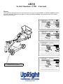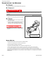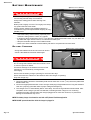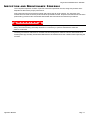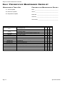
1
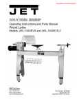
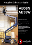
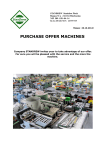
WARNING ! The AB38N Machine has been re-assessed to ensure compliance to the Machinery Directive (2006/42/EC). The Machine rating has been changed from: 2 People Indoors and Outdoors. To 2 People Indoors and 1 Person Outdoors. Please attach to the front cover of your manual to 04243 AB38 Serial Numbers 3700 – Current ENGLISH When contacting UpRight for service or parts information, be sure to include the MODEL and SERIAL NUMBERS from the equipment nameplate. Should the nameplate be missing, the SERIAL NUMBER is also stamped on top of the chassis above the front axle pivot. UpRight MODEL AB38W MAX. PLATFORM HEIGHT MAX. PLATFORM LOAD VIGO CENTRE WASHINGTON, TYNE & WEAR, UK. SERIAL No. 11.5m UNLADEN WEIGHT 400N MAX. LATERAL FORCE MAX. CHASSIS INCLINATION MAX. GRADEABILITY 36% MAX. FORWARD SPEED 3200 kg 200kg 2 Persons + 40kg. Equipment MAX. WIND SPEED 12.5 m/s 48V 0° BATTERY VOLTAGE 240V CHARGER INPUT VOLTAGE 1.1 m/s NOMINAL POWER 4kW CAUTION:ONLY TRAINED & AUTHORISED PERSONNEL MAY USE THIS MACHINE-CONSULT OPERATORS MANUAL BEFORE USE. THIS PLATFORM IS NOT ELECTRICALLY INSULATED 58472-008 UpRight MODEL AB38N MAX. PLATFORM HEIGHT MAX. PLATFORM LOAD 400N MAX. LATERAL FORCE 36% MAX. FORWARD SPEED 3800 kg 215kg 2 Persons + 55kg. Equipment MAX. CHASSIS INCLINATION MAX. GRADEABILITY VIGO CENTRE WASHINGTON, TYNE & WEAR, UK. SERIAL No. 11.5m UNLADEN WEIGHT MAX. WIND SPEED 12.5 m/s 48V 0° BATTERY VOLTAGE CHARGER INPUT VOLTAGE 1.1 m/s 240V NOMINAL POWER 4kW CAUTION:ONLY TRAINED & AUTHORISED PERSONNEL MAY USE THIS MACHINE-CONSULT OPERATORS MANUAL BEFORE USE. THIS PLATFORM IS NOT ELECTRICALLY INSULATED 58472-000 UpRight VIGO CENTRE WASHINGTON, TYNE & WEAR, UK. MODEL AB38N SERIAL No. 475 lbs (2 PERSONS + 120 lbs) MAX. PLATFORM LOAD MAX. PLATFORM HEIGHT 38 ft UNLADEN WEIGHT 9057 lbs MAX. PLATFORM REACH 18ft 4in MAX. LATERAL FORCE 90 lbs MAX. WIND SPEED 28 mph MAX. GRADEABILITY 36% MAX. CHASSIS INCLINATION 0° MAX. HYDRAULIC PRESSURE 2105psi BATTERY VOLTAGE 48V dc CHARGER INPUT VOLTAGE 110/120V NOMINAL POWER 5.4 hp MAX. FORWARD SPEED 2.5mph THIS MACHINE IS MANUFACTURED TO COMPLY WITH ANSI A92.5 - 1992 CAUTION: ONLY TRAINED & AUTHORISED PERSONNEL MAY USE THIS MACHINE-CONSULT OPERATORS MANUAL BEFORE USE. THIS PLATFORM IS NOT ELECTRICALLY INSULATED 58472-002 UpRight VIGO CENTRE, WASHINGTON, TYNE & WEAR, UK MODEL AB38W SERIAL No. 475 lbs (2 PERSONS + 120 lbs) MAX. PLATFORM LOAD MAX. PLATFORM HEIGHT 38 ft UNLADEN WEIGHT 7496 lbs MAX. PLATFORM REACH 18ft 4in MAX. LATERAL FORCE 90 lbs MAX. WIND SPEED 28 mph MAX. CHASSIS INCLINATION 0° MAX. GRADEABILITY 36% MAX. HYDRAULIC PRESSURE 2105psi Serial number stamped on floor of chassis beneath the steering cylinder. BATTERY VOLTAGE 48V dc CHARGER INPUT VOLTAGE 110/120V MAX. FORWARD SPEED 2.5mph NOMINAL POWER 5.4 hp THIS MACHINE IS MANUFACTURED TO COMPLY WITH ANSI A92.5 - 1992 CAUTION: ONLY TRAINED & AUTHORISED PERSONNEL MAY USE THIS MACHINE-CONSULT OPERATORS MANUAL BEFORE USE. THIS PLATFORM IS NOT ELECTRICALLY INSULATED 58472-006 www.upright.com OPERATION MANUAL WARNING All personnel shall carefully read, understand and follow all safety rules and operating instructions before operating or performing maintenance on any UpRight aerial work platform. Safety Rules Electrocution Hazard Tip Over Hazard Collision Hazard Fall Hazard A 83B g t h iRp U THIS MACHINE IS NOT INSULATED! NEVER elevate the platform or drive the machine while elevated unless the machine is on a firm, level surface. NEVER position the platform without first checking for overhead obstructions or other hazards. NEVER climb, stand, or sit on platform guardrails or midrail. USE OF THE AERIAL WORK PLATFORM: This aerial work platform is intended to lift persons and his tools as well as the material used for the job. It is designed for repair and assembly jobs and assignments at overhead workplaces (ceilings, cranes, roof structures, buildings etc.). All other uses of the aerial work platform are prohibited! THIS AERIAL WORK PLATFORM IS NOT INSULATED! For this reason it is imperative to keep a safe distance from live parts of electrical equipment! Exceeding the specified permissible maximum load is prohibited! See “Platform Capacity” for details. The use and operation of the aerial work platform as a lifting tool or a crane is prohibited! NEVER exceed the manual force allowed for this machine. See “Manual Force” for details. DISTRIBUTE all platform loads evenly on the platform. NEVER operate the machine without first surveying the work area for surface hazards such as holes, drop-offs, bumps, curbs, or debris; and avoiding them. OPERATE machine only on surfaces capable of supporting wheel loads. NEVER operate the machine when wind speeds exceed this machine’s wind rating. “Beaufort Scale” for details. IN CASE OF EMERGENCY push EMERGENCY STOP switch to deactivate all powered functions. IF ALARM SOUNDS while platform is elevated, STOP, carefully lower platform. Move machine to a firm, level surface. Climbing up the railing of the platform, standing on or stepping from the platform onto buildings, steel or prefab concrete structures, etc., is prohibited! Dismantling the entry gate or other railing components is prohibited! Always make certain that the entry gate is closed and securely locked! It is prohibited to keep the entry gate in an open position when the platform is raised! To extend the height or the range by placing of ladders, scaffolds or similar devices on the platform is prohibited! NEVER perform service on machine while platform is elevated without blocking elevating assembly. INSPECT the machine thoroughly for cracked welds, loose or missing hardware, hydraulic leaks, loose wire connections, and damaged cables or hoses before using. VERIFY that all labels are in place and legible before using. NEVER use a machine that is damaged, not functioning properly, or has damaged or missing labels. To bypass any safety equipment is prohibited and presents a danger for the persons on the aerial work platform and in its working range. NEVER charge batteries near sparks or open flame. Charging batteries emit explosive hydrogen gas. Modifications to the aerial work platform are prohibited or permissible only at the approval by UpRight. AFTER USE, secure the work platform from unauthorized use by turning the keyswitch off and removing key. The driving of MEWP’s on the public highway is subject to regulations made under the Road Traffic Acts. ALWAYS use a full body harness, prior to raising the platform, as recommended by the Health and Safety Executive (H1/05/05) Page 1 C ONTENTS Safety Rules . . . . . . . . . . . . . . . . . . . . . . . . . . . . . . . . . . . . . . . . . . . . . . . . . . . . . . . . . . . . . . . . . . . . Page 1 Introduction & General Description. . . . . . . . . . . . . . . . . . . . . . . . . . . . . . . . . . . . . . . . . . . . . . . . . Page 3 Special Limitations . . . . . . . . . . . . . . . . . . . . . . . . . . . . . . . . . . . . . . . . . . . . . . . . . . . . . . . . . . . . . . Page 4 Controls & Indicators . . . . . . . . . . . . . . . . . . . . . . . . . . . . . . . . . . . . . . . . . . . . . . . . . . . . . . . . . . . . Page 5 Pre-Operation & Safety Inspection . . . . . . . . . . . . . . . . . . . . . . . . . . . . . . . . . . . . . . . . . . . . . . . . . Page 5 System Functions . . . . . . . . . . . . . . . . . . . . . . . . . . . . . . . . . . . . . . . . . . . . . . . . . . . . . . . . . . . . . . . Page 6 Operation . . . . . . . . . . . . . . . . . . . . . . . . . . . . . . . . . . . . . . . . . . . . . . . . . . . . . . . . . . . . . . . . . . . . . . Page 6 Emergency Lowering . . . . . . . . . . . . . . . . . . . . . . . . . . . . . . . . . . . . . . . . . . . . . . . . . . . . . . . . . . . . Page 7 Transporting the Machine . . . . . . . . . . . . . . . . . . . . . . . . . . . . . . . . . . . . . . . . . . . . . . . . . . . . . . . . Page 8 Hour Meter . . . . . . . . . . . . . . . . . . . . . . . . . . . . . . . . . . . . . . . . . . . . . . . . . . . . . . . . . . . . . . . . . . . . . Page 8 Maintenance. . . . . . . . . . . . . . . . . . . . . . . . . . . . . . . . . . . . . . . . . . . . . . . . . . . . . . . . . . . . . . . . . . . . Page 9 Battery Maintenance . . . . . . . . . . . . . . . . . . . . . . . . . . . . . . . . . . . . . . . . . . . . . . . . . . . . . . . . . . . . Page 10 Inspection & Maintenance Schedule . . . . . . . . . . . . . . . . . . . . . . . . . . . . . . . . . . . . . . . . . . . . . . . Page 11 Daily Preventative Maintenance Checklist . . . . . . . . . . . . . . . . . . . . . . . . . . . . . . . . . . . . . . . . . . Page 12 Decal Location. . . . . . . . . . . . . . . . . . . . . . . . . . . . . . . . . . . . . . . . . . . . . . . . . . . . . . . . . . . . . . . . . Page 13 Specifications . . . . . . . . . . . . . . . . . . . . . . . . . . . . . . . . . . . . . . . . . . . . . . . . . . . . . . . . . . . . . . . . . Page 14 Page 2 Operation Manual Introduction I NTRODUCTION This manual covers the AB38N and the AB38W Aerial Work Platforms. This manual must be stored on the machine at all times. Read, understand and follow all safety rules and operating instructions before attempting to operate the machine. G ENERAL D ESCRIPTION ! W A R N I N G ! DO NOT use the maintenance platform without guardrails properly assembled and in place. Figure 1: AB38 1. Platform 2. Entry Bar 2 3. Elevating Assembly 1 4 5 3 4. Platform Controls 6 5. Manual Case 6. Lower Controls 7. Hydraulic Reservoir 8. Level Sensor 9. Batteries 10. Emergency Lowering Valves 11. Battery Charger 8 10 11 9 7 10 Operation Manual Page 3 Special Limitations S PECIAL L IMITATIONS Travel with the platform raised is limited to creep speed range. Elevating the platform is limited to firm, level surfaces only. ! D A N G E R ! The elevating function shall ONLY be used when the work platform is level and on a firm surface. The work platform is NOT intended to be driven over uneven, rough, or soft terrain. PLATFORM CAPACITY Two people and tools may occupy the platform. The maximum platform capacity for the AB38N/W is stated in the ‘Specifications’ on page 14. ! D A N G E R ! DO NOT exceed the maximum platform capacity or the platform occupancy limits for this machine. MANUAL FORCE Manual force is the force applied by the occupants to objects such as walls or other structures outside the work platform. The maximum allowable manual force is limited to 200 N (45 lbs.) of force per occupant, with a maximum of 400 N (90 lbs.) for two occupants. ! D A N G E R ! DO NOT exceed the maximum amount of manual force for this machine. LIFT OVERLOAD ALARM The AB38 is fitted with a load sensing system designed to comply with the requirements of BS EN 280: 2001 If a load equivalent to 90% of safe working load is lifted a fault code “03” will be displayed on the digital display on the platform control box. If a load which is greater than the safe working load is present in the basket all machine functions will cease to operate and an acoustic warning will sound. In order to return to normal operation a load equal to or less than the safe working load must be present in the basket and the power must be re-cycled, power can be re-cycled by pushing the emergency stop button and releasing it again. BEAUFORT SCALE Never operate the machine when wind speeds exceed 12.5 m/s (28mph) [Beaufort scale 6]. BEAUFORT RATING 3 4 5 6 7 Page 4 m/s WIND SPEED km/h ft/s mph GROUND CONDITIONS 3,4~5,4 12,25~19,4 11.5~17.75 7.5~12.0 Papers and thin branches move, flags wave. 5,4~8,0 19,4~28,8 17.75~26.25 12.0~18 Dust is raised, paper whirls up, and small branches sway. 8,0~10,8 28,8~38,9 26.25~35.5 18~24.25 Shrubs with leaves start swaying. Wave crests are apparent in ponds or swamps. 10,8~13,9 38,9~50,0 35.5~45.5 24.5~31 Tree branches move. Power lines whistle. It is difficult to open an umbrella. 13,9~17,2 50,0~61,9 45.5~56.5 31.~38.5 Whole trees sway. It is difficult to walk against the wind. Operation Manual Controls and Indicators C ONTROLS AND I NDICATORS The operator shall know the location of each control and indicator and have a thorough knowledge of the function and operation of each before attempting to operate the unit. Figure 2: Controls and Indicators Upper Controls 1. Emergency Stop 1 2. Cage Level 3. Upper Boom 11 4. Lower Boom 10 2 5. Drive 9 3 6. Horn 7. Slew (Rotate) 4 8. Display 5 9. Telescope 10. Joystick 11. Key Switch (on side of box) 6 7 8 7 Lower Controls 1 1. Emergency Stop 2. Upper Boom 2 3. Lower Boom 4. Slew (Rotate) 3 5. Telescope 6. Enable 7. Analog Rocker 4 5 6 P RE -O PERATION S AFETY I NSPECTION NOTE: Carefully read, understand and follow all safety rules, operating instructions, labels and National Safety Instructions/Requirements. Perform the following steps each day before use. 1. Remove the Chassis Covers and inspect for damage, fluid leaks or missing parts. 2. Check the level of the hydraulic fluid with the platform fully lowered. Remove the Chassis Covers and remove the reservoir cap, fluid should be visible on the dipstick. Add recommended hydraulic fluid if necessary. See “Specifications” on page 14. 3. Check that the fluid level in the batteries is correct. See “Battery Maintenance” on page 10. 4. Verify that the batteries are charged. 5. Check that the A.C. extension cord has been disconnected from the chassis outlet. 6. Check that all guardrails are in place and all fasteners are properly tightened. 7. Inspect the machine thoroughly for cracked welds and structural damage, loose or missing hardware, hydraulic leaks, damaged control cable and loose wire connections. Operation Manual Page 5 System Function Inspection S YSTEM F UNCTION I NSPECTION Refer to Figure 1 and Figure 2 for the locations of various controls and indicators. ! W A R N I N G ! STAND CLEAR of the work platform while performing the following checks. Before operating the machine, survey the work area for surface hazards such as holes, drop-offs, bumps and debris. Check in ALL directions, including above the work platform, for obstructions and electrical conductors. Protect the control console cable from possible damage while performing checks. 1. Move the machine, if necessary, to an unobstructed area to allow for full elevation. 2. Pull Chassis Emergency Stop Switch to the ON position. 3. Pull Platform Emergency Stop Switch to the ON position. 4. Visually inspect the elevating assembly, lift cylinder, cables, and hoses for cracked welds and structural damage, loose hardware, hydraulic leaks, loose wire connections, and erratic operation. Check for missing or loose parts. 5. Test each machine function (Lift, Slew, Telescope) from the lower control station by pressing and holding the desired function button then moving the Analog Rocker to the Up or Down position (ref: chassis controls illustration on page 5) 6. Open the Emergency Lowering Valve (see Figure 3) by pulling the knob out to check for proper operation. When the platform is lowered, release the knob. 7. Push the Chassis Emergency Stop Switch to check for proper operation. All machine functions should be disabled. Twist the Chassis Emergency Stop Switch to resume. 8. Climb onto the cage. 9. Check that the route is clear of obstacles (persons, obstructions, debris), is level, and is capable of supporting the wheel loads. 10. Mount the platform and properly close the drop bar. 11. Test each machine function (Drive, Lift, Slew, Telescope, Platform Rotate, Cage Level) from the upper control station by pressing the desired function button then moving the Joystick to the Forward or Back position (ref: platform controls illustration on page 5) 12. Push the Platform Emergency Stop Switch to check for proper operation. All machine functions should be disabled. Pull out the Platform Emergency Stop Switch to resume. O PERATION Before operating the work platform, ensure that the Pre-Operation Safety Inspection has been completed and that any deficiencies have been corrected. Never operate a damaged or malfunctioning machine. The operator must be thoroughly trained on this machine. ELEVATING THE PLATFORM 1. Select either the lower or upper boom lift function button (the button will illuminate to confirm selection). 2. While engaging the Interlock Switch, push the Control Handle forward. 3. If the machine is not level the tilt alarm will sound and the machine will not lift. LOWERING THE PLATFORM 1. Select either the lower or upper boom lift function button (the button will illuminate to confirm selection). 2. While engaging the Interlock Switch, pull the Control Handle backwards. 3. If the machine is not level the tilt alarm will sound and the machine will only descend. Page 6 Operation Manual Operation ROTATING THE PLATFORM 1. Select the rotate function button (the button will illuminate to confirm selection). 2. While engaging the Interlock Switch, move the Control Handle forwards or backwards to achieve clockwise or counter clockwise rotation. 3. If the machine is not level the tilt alarm will sound and the machine will not rotate. OPERATING THE TE L E S C O P E 1. Select telescope function button (the button will illuminate to confirm selection). 2. While engaging the Interlock Switch, move the Control Handle forwards or backwards to extend or retract the telescopic boom. 3. If the machine is not level the tilt alarm will sound and the telescope boom will only retract. NOTE: The AB38W is equipped with a safety system preventing any drive motion when the machine is out of the stow position and with the telescope extended beyond a pre-set limit. LEVELLING THE CAGE 1. Select platform level function button (the button will illuminate to confirm selection). 2. While engaging the Interlock Switch, move the Control Handle forwards or backwards to adjust the floor angle of the cage (this can only be done when the machine is in the stowed position). 3. If the machine is not level the tilt alarm will sound and the machine will not operate. EMERGENCY LOWERING ! W A R N I N G ! If the platform should fail to lower, NEVER climb down the elevating assembly. Stand clear of the elevating assembly while operating the Emergency Lowering Valve Knob. Figure 3: Emergency Lowering Valve Ask a person on the ground to open the Emergency Lowering Valve to lower the platform. The Emergency Lowering Valve is located on the base of each lift cylinder. 1. Open the Emergency Lowering Valve by pulling the knob out. 2. To close, release the knob. NOTE: The platform will not elevate if the Emergency Lowering Valve is open. Emergency Lowering Valves AFTER USE EACH DAY 1. Ensure that the platform is fully lowered. 2. Park the machine on a firm level surface, preferably under cover, secure against vandals, children and unauthorized operation. 3. Turn the Chassis Key Switch to OFF and remove the key to prevent unauthorized operation. Operation Manual Page 7 Transporting the Machine TRANSPORTING THE M ACHINE BY CRANE Secure the straps to chassis lifting/tie down points only. BY FORKLIFT ! D A N G E R ! Forklifting and Lifting by Crane are for transport only. See specifications for weight of machine and be certain that forklift is of adequate capacity to lift the machine. Figure 4: Transporting the Machine Forklift from the side by lifting under the Chassis. B Y TR U C K 1. Maneuver the machine into transport position and chock wheels. 2. Secure the machine to the transport vehicle with chains or straps of adequate load capacity attached to the chassis lifting/tie down points. C A U T I O N Over tightening of the chains or straps attached to the Tie Down lugs may result in damage to the machine Lift / Tie Down Points HOUR METER To access the hour meter function perform the following steps. 1. Climb into the basket (with the machine powered up) 2. Push the platform emergency stop button. 3. Hold down the following buttons, Horn, Telescope & Upper Boom Lift. 4. While holding the buttons twist the emergency stop button to return power to the machine. 5. “hr” will now be displayed on the read-out, Pressing the right turn button will scroll through the accumulated hours two digits at a time. For example, if pressing the right turn button once displays “20”, pressing it a 2nd time displays “58”, and pressing it a 3rd time displays “hr”, the elapsed time of operation is 2058 hours. Page 8 Operation Manual Maintenance M AINTENANCE ! W A R N I N G ! Never perform service while the platform is elevated. HYDRAULIC FLUID The hydraulic fluid reservoir is located in the chassis door. Figure 5: Hydraulic Fluid Reservoir and Dipstick NOTE: Never add fluid if the platform is elevated. CHECK HYDRAULIC FLUID 1. Make sure that the platform is fully lowered. 2. Open the chassis door. 3. Remove the filler cap from the hydraulic fluid reservoir. 4. Check the fluid level on the dipstick on the filler cap. Filler Cap 5. Add the appropriate fluid to bring the level to show on the dipstick. See “Specifications” on page 14 Operation Manual Page 9 Maintenance BATTER Y MAINTENANCE Figure 6: Access to Batteries ! W A R N I N G ! Hazard of explosive gas mixture. Keep sparks, flame, and smoking material away from batteries. Always wear safety glasses when working near batteries. Battery fluid is highly corrosive. Thoroughly rinse away any spilled fluid with clean water. Always replace batteries with UpRight batteries or manufacturer approved replacements weighing 26,3 kg (58 lbs.) each. • Check the battery fluid level daily, especially if the machine is being used in a warm, dry climate. • If electrolyte level is lower than 10 mm (3/8 in.) above the plates add distilled water only. DO NOT use tap water with high mineral content, as it will shorten battery life. • Keep the terminals and tops of the batteries clean. • Refer to the Service Manual to extend battery life and for complete service instructions. BATTERY CHARGING Figure 7: Battery Charge Indicator Charge the batteries at the end of each work shift or sooner if the batteries have been discharged. ! W A R N I N G Battery Charge Indicator ! Charge the batteries in a well ventilated area. Do not charge the batteries when the machine is near a source of sparks or flames. Permanent damage to the batteries will result if the batteries are not immediately recharged after discharging. Never leave the battery charger operating for more than two days. Never disconnect the cables from the batteries when the charger is operating. Keep the charger dry. 1. Check the battery fluid level. If the battery fluid level is lower than 10 mm (3/8 in.) above the plates add distilled water only. 2. Connect an appropriate extension cord to charger outlet plug in Right Module Door. Plug the extension cord into a properly grounded outlet of proper voltage and frequency. 3. The charger turns on automatically after a short delay. The LED charge indicator will illuminate. After completion of the charge cycle the LED will blink, indicating that the charger is in a continuing maintenance mode. DO NOT leave the charger plugged in for more than 48 hours, as permanent damage to the batteries may occur. NOTE: The battery charger circuit must be used with a GFI (Ground Fault Interrupt) outlet. NOTE: DO NOT operate the machine while the charger is plugged in. Page 10 Operation Manual Inspection and Maintenance Schedule I NSPECTION AND M AINTENANCE S CHEDULE The Complete Inspection consists of periodic visual and operational checks, along with periodic minor adjustments that assure proper performance. Daily inspection will prevent abnormal wear and prolong the life of all systems. The inspection and maintenance schedule should be performed at the specified intervals. Inspection and maintenance shall be performed by personnel who are trained and familiar with mechanical and electrical procedures. ! W A R N I N G ! Before performing preventative maintenance, familiarize yourself with the operation of the machine. Always block the elevating assembly whenever it is necessary to perform maintenance while the platform is elevated. The daily preventative maintenance checklist has been designed for machine service and maintenance. Please photocopy the Daily Preventative Maintenance Checklist and use the checklist when inspecting the machine. Operation Manual Page 11 Daily Preventative Maintenance Checklist D AILY P REVENTATIVE M AINTENANCE C HECKLIST MAINTENANCE TABLE KEY PREVENTATIVE MAINTENANCE REPORT Y = Yes/Acceptable Date: _______________________________________ N = No/Not Acceptable Owner: ______________________________________ R = Repaired/Acceptable Model No: ___________________________________ Serial No:____________________________________ Serviced By: _________________________________ ___________________________________________ COMPONENT Battery Chassis Control Cable Controller Drive Motor/Gearbox Elevating Assembly Emergency Hydraulic System Entire Unit Hydraulic Fluid Hydraulic Pump Hydraulic System Labels Platform Deck and Rails Platform Deck and Rails Tires Page 12 INSPECTION OR SERVICES Check electrolyte level. Check battery cable condition. Check hoses for pinch or rubbing points. Check welds for cracks. Check the exterior of the cable for pinching, binding or wear. Check switch operation. Check for operation and leaks. Inspect for structural cracks. Operate the emergency lowering valve and check for serviceability. Check for and repair collision damage. Check fluid level. Check for hose fitting leaks. Check for leaks. Check for peeling, missing, or unreadable labels & replace. Check welds for cracks. Check condition of deck. Check for damage. Y N R Operation Manual Decal Location D ECAL L OCATION ITEM 1 2 3 4 5 6 7 8 9 10 11 12 13 14 15 16 17 18 19 20 21 Operation Manual PART NO. 500264-000 501870-000 500257-000 057695-000 502480-000 057696-000 057429-000 057430-000 057692-000 058472-000 500467-000 058881-001 058080-000 058186-000 500423-006 501869-000 058181-000 057392-000 058860-000 500438-000 500422-006 DESCRIPTION DECAL - UpRight AB38 BOOM DECAL - LOWER CONTROL BOX DECAL - AB38 LOGO DECAL - BALLAST STRIP DECAL - EMERGENCY LOWERING DECAL - ‘UpRight’ LOGO DECAL - BATTERY FLUID LEVEL DECAL - EXPLOSION HAZARD DECAL - IMPORTANT BEFORE USING NAMEPLATE DECAL - HANDPUMP DECAL - HAZARD TAPE DECAL - CAGE LEVELLING DECAL - ON/OFF UPPER CONTROL OPERATOR MANUAL CE DECAL - UPPER CONTROL BOX DECAL - 3 POINT DECAL - S.W.L. LARGE DECAL - PINCH POINT DECAL - LOWER CONTROL COVER SERVICE & PARTS MANUAL QTY. 2 1 1 1 2 2 2 2 1 1 1 2 1 1 1 1 1 1 2 1 1 Page 13 Specifications S PECIFICATIONS Table 1-1 : Specifications ITEM Duty Cycle Platform Size Max. Platform Capacity CE Version ANSI Version Max. Number of Occupants Height Maximum Working Height Maximum Platform Height Min. Platform Floor Height Max. Working Outreach Platform Height at Maximum Outreach Stowed Dimensions Length Width Height Ground Clearence Wheel Base X Guage Rotation Gross Weight-CE Version Gross Weight-ANSI Version Drive Speed Stowed Drive Speed Elevated Maximum Gradeability Inside Turning Radius Outside Turning Radius Power Source System Voltage Battery Charger Hydraulic Tank Capacity Max. Hydraulic Pressure Hydraulic Oil Lift System Control System Wheels/Tyres Braking Sound Pressure Level at Page 14 METRIC IMPERIAL 45% of 8 hour shift 0.7 m x 1.3 m (inside guardrails) 200kg (W) or 215kg (N) 215 kg 2 People 441lbs(W) or 475lbs (N) 475 lbs 2 People 13.45 m 11.45 m 0.65 m 6.10 m 44.12 ft 37.56 ft 2.13 ft 20.00 ft 5.40 m 17.72 ft 4.04 m 13.25 ft 1.72m (W) or 1.5m (N) 5.61ft (W) or 4.92 ft (N) 2.00 m 6.56 ft 0.13 m 0.43 ft 2.00m x 1.49m (W) or 1.27m (N) 6.56 ft (W) x 4.16 ft (N) 362 degrees non-continuous 362 degrees non-continuous 3200kg (W) or 3800kg (N) 7055lbs (W) or 8378lbs (N) 3400kg (W) or 4108kg (N) 7496lbs (W) or 9057lbs (N) 0 - 4 km /h 0 - 2.49 m ph 0 - 0.72 km/h 0 - 0.45 m ph 36% 36% 0.40 m 1.31 ft 2.66 m (W) or 2.4 m (N) 8.72ft (W) or 7.87ft (N) 48V DC 4kw, 8 x 6V 220Ah Batteries 48V DC 5.4 HP, 8 x 6V 220Ah Batteries 48V 48V 48V 25A 220/110VAC 50/60 Hz 48V 25A 220/110VAC 50/60 Hz 25 Litres 6.5 Gallons US 175 bar 2540 psi ISO #46 ISO #46 2 Double acting lift cylinders with 2 Double acting lift cylinders with Lock Valves and Manual Emergency Lock Valves and Manual Emergency Lowering Facility. Lowering Facility. 1 Double Acting Telescopic Cylinder 1 Double Acting Telescopic Cylinder One handed Proportional Joystick One handed Proportional Joystick Operating Energy Efficient Motor Operating Energy Efficient Motor Control System Control System 400 mm Diameter Steel Disc Wheel 15.75 inch Diameter Steel Disc Wheel with Solid all Surface tyres with Solid all Surface tyres Autom atic Spring Applied Automatic Spring Applied Hydraulic Release Hydraulic Release 70 db(A) 70 db(A) Operation Manual Local Distributor: Lokaler Vertiebshändler: Distributeur local: El Distribuidor local: Il Distributore locale: USA Europe TEL: +1 (559) 443 6600 FAX: +1 (559) 268 2433 TEL: +44 (0) 845 1550 058 FAX: +44 (0) 195 2299 948 www.upright.com PN - 500423-006