1
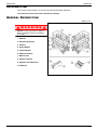
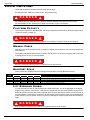
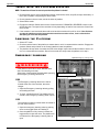
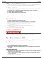
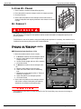
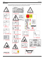
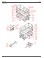
X 26-32
X26 Serial Numbers 50906 – 53100
ENGLISH
When contacting Upright for service or parts information, be sure to include the MODEL and SERIAL NUMBERS from the
equipment nameplate. Should the nameplate be missing, the SERIAL NUMBER is also stamped on top of the chassis
above the front axle pivot.
Stamped Serial Number
Estampille de numéro de série
Eingestanzte Seriennummer
OPERATION MANUAL
WARNING
All personnel shall carefully read, understand and follow all safety rules and operating
instructions before operating or performing maintenance on any UpRight aerial work platform.
Safety Rules
Electrocution Hazard
THIS MACHINE IS NOT
INSULATED!
Tip Over Hazard
Fall Hazard
Collision Hazard
NEVER elevate the platform or drive
NEVER position the platform
the machine while elevated unless the without first checking for overhead
machine is on a firm, level surface.
obstructions or other hazards.
NEVER climb, stand, or sit on
platform guardrails or midrail.
USE OF THE AERIAL WORK PLATFORM: This aerial work platform is intended to lift persons and his tools as well as the material
used for the job. It is designed for repair and assembly jobs and assignments at overhead workplaces (ceilings, cranes, roof structures,
buildings etc.). All other uses of the aerial work platform are prohibited!
THIS AERIAL WORK PLATFORM IS NOT INSULATED! For this reason it is imperative to keep a safe distance from live parts of electrical equipment!
Exceeding the specified permissible maximum load is prohibited! See “Special Limitations” on page 4 for details.
The use and operation of the aerial work platform as a lifting tool or a crane (lifting of loads from below upwards or from up high on
down) is prohibited!
NEVER exceed the manual force allowed for this machine. See “Special Limitations” on page 4 for details.
DISTRIBUTE all platform loads evenly on the platform.
NEVER operate the machine without first surveying the work area for surface hazards such as holes, drop-offs, bumps, curbs, or debris;
and avoiding them.
OPERATE machine only on surfaces capable of supporting wheel loads.
NEVER operate the machine when wind speeds exceed this machine’s wind rating. See “Beaufort Scale” on page 4 for details.
IN CASE OF EMERGENCY push EMERGENCY STOP switch to deactivate all powered functions.
IF ALARM SOUNDS while platform is elevated, STOP, carefully lower platform. Move machine to a firm, level surface.
Climbing up the railing of the platform, standing on or stepping from the platform onto buildings, steel or prefab concrete structures, etc.,
is prohibited!
Dismantling the swing gate or other railing components is prohibited! Always make certain that the swing gate is closed and securely
locked!
It is prohibited to keep the swing gate in an open position (held open with tie-straps) when the platform is raised!
To extend the height or the range by placing of ladders, scaffolds or similar devices on the platform is prohibited!
NEVER perform service on machine while platform is elevated without blocking elevating assembly.
INSPECT the machine thoroughly for cracked welds, loose or missing hardware, hydraulic leaks, loose wire connections, and damaged
cables or hoses before using.
VERIFY that all labels are in place and legible before using.
NEVER use a machine that is damaged, not functioning properly, or has damaged or missing labels.
To bypass any safety equipment is prohibited and presents a danger for the persons on the aerial work platform and in its working
range.
NEVER charge batteries near sparks or open flame. Charging batteries emit explosive hydrogen gas.
Modifications to the aerial work platform are prohibited or permissible only at the approval by UpRight.
AFTER USE, secure the work platform from unauthorized use by turning both keyswitches off and removing key.
The driving of MEWPs on the public highways is subject to regulations made under the Road Traffic Acts.
Page 1
504165-002
C ONTENTS
Introduction . . . . . . . . . . . . . . . . . . . . . . . . . . . . . . . . . . . . . . . . . . . . . . . . . . . . . . . . . . . . . . . . . . . . . . . . . .3
General Description . . . . . . . . . . . . . . . . . . . . . . . . . . . . . . . . . . . . . . . . . . . . . . . . . . . . . . . . . . . . . . . . . . .3
Special Limitations . . . . . . . . . . . . . . . . . . . . . . . . . . . . . . . . . . . . . . . . . . . . . . . . . . . . . . . . . . . . . . . . . . . .4
Platform Capacity . . . . . . . . . . . . . . . . . . . . . . . . . . . . . . . . . . . . . . . . . . . . . . . . . . . . . . . . . . . . . . . . . . . . . . . . . . .
Manual Force . . . . . . . . . . . . . . . . . . . . . . . . . . . . . . . . . . . . . . . . . . . . . . . . . . . . . . . . . . . . . . . . . . . . . . . . . . . . . .
Beaufort Scale. . . . . . . . . . . . . . . . . . . . . . . . . . . . . . . . . . . . . . . . . . . . . . . . . . . . . . . . . . . . . . . . . . . . . . . . . . . . . .
Lift Overload Alarm . . . . . . . . . . . . . . . . . . . . . . . . . . . . . . . . . . . . . . . . . . . . . . . . . . . . . . . . . . . . . . . . . . . . . . . . . .
4
4
4
4
Controls and Indicators . . . . . . . . . . . . . . . . . . . . . . . . . . . . . . . . . . . . . . . . . . . . . . . . . . . . . . . . . . . . . . . .5
Pre-Operation Safety Inspection . . . . . . . . . . . . . . . . . . . . . . . . . . . . . . . . . . . . . . . . . . . . . . . . . . . . . . . . .6
System Function Inspection . . . . . . . . . . . . . . . . . . . . . . . . . . . . . . . . . . . . . . . . . . . . . . . . . . . . . . . . . . . .7
Operation. . . . . . . . . . . . . . . . . . . . . . . . . . . . . . . . . . . . . . . . . . . . . . . . . . . . . . . . . . . . . . . . . . . . . . . . . . . .8
Platform Extension . . . . . . . . . . . . . . . . . . . . . . . . . . . . . . . . . . . . . . . . . . . . . . . . . . . . . . . . . . . . . . . . . . . . . . . . . . 8
Travel With the Platform Lowered . . . . . . . . . . . . . . . . . . . . . . . . . . . . . . . . . . . . . . . . . . . . . . . . . . . . . . . . . . . . . . . 8
Steering . . . . . . . . . . . . . . . . . . . . . . . . . . . . . . . . . . . . . . . . . . . . . . . . . . . . . . . . . . . . . . . . . . . . . . . . . . . . . . . . . . . 8
Elevating the Platform . . . . . . . . . . . . . . . . . . . . . . . . . . . . . . . . . . . . . . . . . . . . . . . . . . . . . . . . . . . . . . . . . . . . . . . . 8
Travel With the Platform Elevated. . . . . . . . . . . . . . . . . . . . . . . . . . . . . . . . . . . . . . . . . . . . . . . . . . . . . . . . . . . . . . . 9
Lowering the Platform . . . . . . . . . . . . . . . . . . . . . . . . . . . . . . . . . . . . . . . . . . . . . . . . . . . . . . . . . . . . . . . . . . . . . . . . 9
Emergency Lowering. . . . . . . . . . . . . . . . . . . . . . . . . . . . . . . . . . . . . . . . . . . . . . . . . . . . . . . . . . . . . . . . . . . . . . . . . 9
X26. . . . . . . . . . . . . . . . . . . . . . . . . . . . . . . . . . . . . . . . . . . . . . . . . . . . . . . . . . . . . . . . . . . . . . . . . . . . . . . . . . . 9
X32. . . . . . . . . . . . . . . . . . . . . . . . . . . . . . . . . . . . . . . . . . . . . . . . . . . . . . . . . . . . . . . . . . . . . . . . . . . . . . . . . . . 9
Lower the Guardrails, X26. . . . . . . . . . . . . . . . . . . . . . . . . . . . . . . . . . . . . . . . . . . . . . . . . . . . . . . . . . . . . . . . . . . . 10
Lowering Procedure . . . . . . . . . . . . . . . . . . . . . . . . . . . . . . . . . . . . . . . . . . . . . . . . . . . . . . . . . . . . . . . . . . . . . 10
Raising Procedure . . . . . . . . . . . . . . . . . . . . . . . . . . . . . . . . . . . . . . . . . . . . . . . . . . . . . . . . . . . . . . . . . . . . . . 10
Fold Down guardrails, X32 . . . . . . . . . . . . . . . . . . . . . . . . . . . . . . . . . . . . . . . . . . . . . . . . . . . . . . . . . . . . . . . . . . . 11
Fold Down Procedure . . . . . . . . . . . . . . . . . . . . . . . . . . . . . . . . . . . . . . . . . . . . . . . . . . . . . . . . . . . . . . . . . . . 11
Erection Procedure . . . . . . . . . . . . . . . . . . . . . . . . . . . . . . . . . . . . . . . . . . . . . . . . . . . . . . . . . . . . . . . . . . . . . 11
Towing or Winching . . . . . . . . . . . . . . . . . . . . . . . . . . . . . . . . . . . . . . . . . . . . . . . . . . . . . . . . . . . . . . . . . .12
Parking Brake Release . . . . . . . . . . . . . . . . . . . . . . . . . . . . . . . . . . . . . . . . . . . . . . . . . . . . . . . . . . . . . . . . . . . . . . 12
After Use Each Day. . . . . . . . . . . . . . . . . . . . . . . . . . . . . . . . . . . . . . . . . . . . . . . . . . . . . . . . . . . . . . . . . . . . . . . . . 12
Hour Meter . . . . . . . . . . . . . . . . . . . . . . . . . . . . . . . . . . . . . . . . . . . . . . . . . . . . . . . . . . . . . . . . . . . . . . . . . . . . . . . 12
Transporting the Work Platform . . . . . . . . . . . . . . . . . . . . . . . . . . . . . . . . . . . . . . . . . . . . . . . . . . . . . . . .13
Preparation for Shipment . . . . . . . . . . . . . . . . . . . . . . . . . . . . . . . . . . . . . . . . . . . . . . . . . . . . . . . . . . . . . . . . . . . .
Lifting By Crane. . . . . . . . . . . . . . . . . . . . . . . . . . . . . . . . . . . . . . . . . . . . . . . . . . . . . . . . . . . . . . . . . . . . . . . . . . . .
By Forklift . . . . . . . . . . . . . . . . . . . . . . . . . . . . . . . . . . . . . . . . . . . . . . . . . . . . . . . . . . . . . . . . . . . . . . . . . . . . . . . .
Driving or Winching onto a Truck or Trailer . . . . . . . . . . . . . . . . . . . . . . . . . . . . . . . . . . . . . . . . . . . . . . . . . . . . . . .
13
13
13
13
Maintenance . . . . . . . . . . . . . . . . . . . . . . . . . . . . . . . . . . . . . . . . . . . . . . . . . . . . . . . . . . . . . . . . . . . . . . . .14
Blocking The Elevating Assembly . . . . . . . . . . . . . . . . . . . . . . . . . . . . . . . . . . . . . . . . . . . . . . . . . . . . . . . . . . . . . .
Scissor Brace Installation. . . . . . . . . . . . . . . . . . . . . . . . . . . . . . . . . . . . . . . . . . . . . . . . . . . . . . . . . . . . . . . . .
Scissor Brace Stowage . . . . . . . . . . . . . . . . . . . . . . . . . . . . . . . . . . . . . . . . . . . . . . . . . . . . . . . . . . . . . . . . . .
Battery Maintenance . . . . . . . . . . . . . . . . . . . . . . . . . . . . . . . . . . . . . . . . . . . . . . . . . . . . . . . . . . . . . . . . . . . . . . . .
Battery Charging . . . . . . . . . . . . . . . . . . . . . . . . . . . . . . . . . . . . . . . . . . . . . . . . . . . . . . . . . . . . . . . . . . . . . . .
14
14
14
15
15
Inspection and Maintenance Schedule. . . . . . . . . . . . . . . . . . . . . . . . . . . . . . . . . . . . . . . . . . . . . . . . . . .16
Daily Preventative Maintenance Checklist . . . . . . . . . . . . . . . . . . . . . . . . . . . . . . . . . . . . . . . . . . . . . . . .16
Labels . . . . . . . . . . . . . . . . . . . . . . . . . . . . . . . . . . . . . . . . . . . . . . . . . . . . . . . . . . . . . . . . . . . . . . . . . . . . .17
Specifications . . . . . . . . . . . . . . . . . . . . . . . . . . . . . . . . . . . . . . . . . . . . . . . . . . . . . . . . . . . . . . . . . . . . . . .19
Page 2
Operation Manual
Introduction
504165-002
I NTRODUCTION
This manual covers operation of the X 26-32 Self-Propelled Work Platforms.
This manual must be stored on the machine at all times.
G ENERAL D ESCRIPTION
Figure 1: X 26-32
!
W A R N I N G
!
DO NOT use the maintenance platform
without guardrails properly assembled
and in place
1. Platform
2. Elevating Assembly
3. Chassis
4. Power Module
5. Control Module
6. Platform Controls
7. Manual Case
8. Chassis Controls
9. Hydraulic Fluid Reservoir
10. Batteries
Operation Manual
Page 3
504165-002
Special Limitations
S PECIAL L IMITATIONS
Travel with the platform raised is limited to creep speed range.
Elevating the Work Platform is limited to firm, level surfaces only.
!
D A N G E R
!
The elevating function shall ONLY be used when the work platform is level and on a firm surface.
The work platform is NOT intended to be driven over uneven, rough, or soft terrain.
PLATFORM CAPACITY
The maximum capacity for the MACHINE, including occupants is determined by model and options, and
is listed in “Decals” on page 18.
!
D A N G E R
!
DO NOT exceed the maximum platform capacity or the platform occupancy limits for this machine.
MANUAL FORCE
Manual force is the force applied by the occupants to objects such as walls or other structures outside the
work platform.
The maximum allowable manual force is limited to 200 N (45 lbs.) of force per occupant, with a maximum
of 400 N (90 lbs.) for two or more occupants.
!
D A N G E R
!
DO NOT exceed the maximum amount of manual force for this machine.
BEAUFORT SCALE
Never operate the machine when wind speeds exceed 25 km/h (15 mph) [Beaufort scale 4].
BEAUFORT
RATING
m/s
3
4
5
6
7
3,4~5,4
5,4~8,0
8,0~10,8
10,8~13,9
13,9~17,2
WIND SPEED
km/h
ft/s
12,25~19,4
19,4~28,8
28,8~38,9
38,9~50,0
50,0~61,9
11.5~17.75
17.75~26.25
26.25~35.5
35.5~45.5
45.5~56.5
GROUND CONDITIONS
mph
7.5~12.0
12.0~18
18~24.25
24.5~31
31.~38.5
Papers and thin branches move, flags wave.
Dust is raised, paper whirls up, and small branches sway.
Shrubs with leaves start swaying. Wave crests are apparent in ponds or swamps.
Tree branches move. Power lines whistle. It is difficult to open an umbrella.
Whole trees sway. It is difficult to walk against the wind.
LIFT OVERLOAD ALARM
If a load equivalent to 90% of safe working load is lifted a fault code “03” will be displayed on the digital
display on the platform control box. If a load which is greater than the safe working load is present in the
basket all machine functions will cease to operate and an acoustic warning will sound. In order to return to
normal operation a load equal to or less than the safe working load must be present in the basket and the
power must be re-cycled, power can be re-cycled by pushing the emergency stop button and releasing it
again.
!
D A N G E R
!
Never operate the machine with a platform load greater than the rated capacity.
Page 4
Operation Manual
Controls and Indicators
504165-002
C ONTROLS AND I NDICATORS
Figure 2: Controls and Indicators
Platform Controls
4
6
3
1
1
2.
3.
4.
5.
6.
Drive Selectors
Horn Button
Lift/Lower Button
Emergency Stop Button
Display
Joystick
Chassis Controls
1.
2.
3.
4.
Operation Manual
5
2
1
2
3
4
Keyswitch
Enable Button
Toggle Switch (Up & Down)
Emergency Stop Switch
Page 5
504165-002
Pre-Operation Safety Inspection
P RE -O PERATION S AFETY I NSPECTION
NOTE: Carefully read, understand and follow all safety rules, operating instructions, labels and National Safety
Instructions/Requirements. Perform the following steps each day before use.
1. Open modules and inspect for damage, fluid leaks or missing parts.
Figure 3: Hydraulic Tank
2. Check the level of the hydraulic fluid with
the platform fully lowered. The hydraulic
reservoir is located in the Control Module Door. The fluid level must be
between the MIN and MAX lines. Add
hydraulic fluid if necessary.
3. Check that fluid level in the batteries is
correct.
4. Verify that batteries are charged.
5. Check that A.C. extension cord has
been disconnected from the plug in the
rear of the machine.
6. Check that all guardrails are in place
and all fasteners are properly tightened.
7. Inspect the machine thoroughly for
cracked welds and structural damage,
loose or missing hardware, hydraulic
leaks, damaged control cable, loose wire connections and wheel bolts.
Page 6
Operation Manual
System Function Inspection
504165-002
S YSTEM F UNCTION I NSPECTION
Refer to Figure 2 for the locations of various controls and indicators.
!
W A R N I N G
!
STAND CLEAR of the work platform while performing the following checks.
Before operating the work platform, survey the work area for surface hazards such as holes, drop-offs,
bumps and debris.
Check in ALL directions, including above the work platform, for obstructions and electrical conductors.
Protect the control console cable from possible damage while performing checks.
1. Move the machine, if necessary, to an unobstructed area to allow for full elevation.
2. Pull Chassis Emergency Stop Switch to the ON position.
3. Pull Platform Emergency Stop Switch to the ON position.
4. Turn and hold the Chassis Key Switch to the ON position. Push the Chassis Lift/Lower Switch to the UP
position and raise the platform approximately 2,1 m (7 feet). BLOCK THE ELEVATING ASSEMBLY AS
DESCRIBED ON PAGE 9.
5. Visually inspect the elevating assembly, lift cylinder, cables, and hoses for cracked welds and structural
damage, loose hardware, hydraulic leaks, loose wire connections, and erratic operation. Check for missing or loose parts.
6. Verify that the Depression Mechanism Supports have rotated into position under the machine. REMOVE
THE SCISSOR BRACE AS DESCRIBED ON page 13.
7. Push the Chassis Lift/Lower Switch to the UP position and fully elevate the platform.
8. Partially lower the platform by pushing Chassis Lift/Lower Switch to LOWER, and check for proper operation of the audible lowering alarm.
9. Open the Emergency Lowering Valve (see Figure 5) by pulling the knob out to check for proper operation. When the platform is lowered, release the knob.
10. Push the Chassis Emergency Stop Switch to check for proper operation. All machine functions should
be disabled. Pull out the Chassis Emergency Stop Switch to resume.
11. Check that the route is clear of obstacles (persons, obstructions, holes, and drop-offs, bumps and
debris), is level, and is capable of supporting the wheel loads.
12. Mount the platform and properly close the entrance.
13. Mount the platform and select DRIVE mode.
NOTE: Use both HI and LOW drive (if applicable) when performing the following step.
14. While engaging the Interlock Switch, move the Control Handle to FORWARD, then REVERSE, to check
for speed control.
15. Push the Steering Switch RIGHT, then LEFT, to check for steering control.
16. Select LIFT mode. Grasp the Control Handle, engaging the Interlock Switch, and push it forward to
check platform lift controls. Raise the platform to full elevation.
17. Pull back on the Control Handle. The platform should descend and the audible lowering alarm should
sound.
18. Push the Platform Emergency Stop Switch to check for proper operation. All machine functions should
be disabled. Pull out the Platform Emergency Stop Switch to resume.
Operation Manual
Page 7
504165-002
O PERATION
Before operating the work platform, ensure that the Pre-Operation Safety Inspection has been completed
and that any deficiencies have been corrected. Never operate a damaged or malfunctioning machine.
The operator must be thoroughly trained on this machine.
PLATFORM EXTENSION
Figure 4: Platform Extension
1. Mount the platform and properly close the entrance.
2. Depress the foot lever located at the rear of the platform
extension. Push the platform extension forward until the
pin engages the front stop.
3. To retract the platform extension, depress the foot lever
and pull the platform extension toward the rear of the
machine until the pin engages the rear stop.
TR A V E L W I T H
LOWERED
THE
PLATFORM
1. Check that the route is clear of obstacles (persons,
obstructions, holes, drop-offs, bumps, and debris), is level,
and is capable of supporting the wheel loads.
2. Verify that the Chassis Key Switch is turned to ON and the
Chassis Emergency Stop Switch is ON (pulled out).
3. Mount the platform and properly close the entrance.
4. Check clearances above, below, and to the sides of platform.
5. Pull the Platform Emergency Stop Switch out to the ON position.
6. Select DRIVE mode.
NOTE: Choose between standard drive and extra torque depending on the gradient.
7. Engage the Interlock Switch and move the Control Handle to FORWARD or REVERSE to travel in the
desired direction. The speed of the machine will vary depending on how far from centre the Control
Handle is moved.
STEERING
1. Turn the Drive/Lift Switch to DRIVE.
2. While engaging the Interlock Switch, push the Steering Switch to RIGHT or LEFT to turn the wheels in
the desired direction. Observe the tires while manoeuvring the work platform to ensure proper direction.
NOTE: Steering is not self-centring. Wheels must be returned to the straight ahead position by operating the Steering
Switch.
ELEVATING
THE
PLATFORM
1. Select a firm, level surface.
2. Select LIFT mode.
3. While engaging the Interlock Switch, push the Control Handle forward.
4. If the machine is not level the tilt alarm will sound and the machine will not lift or drive. If the tilt alarm
sounds the platform must be lowered and the machine moved to a firm level surface before
attempting to re-elevate the platform.
NOTE: Depression Mechanism supports will deploy automatically as the platform elevates and will retract after the
platform has been lowered completely and has been driven.
Page 8
Operation Manual
Operation
504165-002
TR A V E L W I T H
THE
PLATFORM ELEVATED
NOTE: The machine will travel at reduced speed when the platform is elevated.
1. Check that the route is clear of obstacles (persons, obstructions, holes, drop-offs, bumps, and debris), is
level, and is capable of supporting the wheel loads.
2. Check clearances above, below, and to the sides of platform.
3. Select DRIVe mode.
4. Engage the Interlock Switch and move the Control Handle to FORWARD or REVERSE to travel in the
desired direction. The speed of the machine will vary depending on how far from centre the Control Handle is moved.
5. If the machine is not level the tilt alarm will sound and the machine will not lift or drive. If the tilt alarm
sounds the platform must be lowered and the machine moved to a firm, level surface before
attempting to re-elevate the platform.
LOWERING
THE
PLATFORM
1. Select LIFT mode.
2. Check around the base of the platform to ensure that no one is in contact with the machine. Engage the
Interlock Switch and pull back on the Control Handle to lower the platform.
3. The platform will stop when it reaches the PPE cutout height. Inspect around the machine to ensure no
one is in contact with the machine. After a four-second time delay, lower the platform as in step 2.
EMERGENCY LOWERING
Figure 5: Emergency Lowering Valve
!
W A R N I N G
!
If the platform should fail to lower, NEVER climb
down the elevating assembly.
Stand clear of the elevating assembly while operating
the Emergency Lowering Valve Knob.
Emergency Lowering Knob
X 26
X26
The Emergency Lowering Valve for the X26 is
located at the rear of the machine, above the
charger.
1. Open the Emergency Lowering Valve by pulling
and holding the knob.
2. To close, release the knob. The platform will not
elevate if the Emergency Lowering Valve is open.
X32
The emergency lowering control switch is located at
the rear of the machine.
Emergency Lowering Button
1. Open the emergency lowering valve by pushing
down on the toggle switch and holding it.
2. Once the platform is fully lowered, release the
toggle switch to close the valve. The platform will
not elevate if the Emergency Lowering Valve is
open.
Operation Manual
X 32
Page 9
504165-002
Operation
LOWER
THE
G U A R D R A I L S , X26
This procedure applies only to the X26 model for the purpose of passing through a standard double doorway. Guardrails must be returned to proper position before using the machine.
LOWERING PROCEDURE
1. Ensure that the slide-out deck extension is fully retracted and the deck pin is locked. Place the Platform
Controls on the floor of the platform.
2. Remove and retain the set screws from the side guardrails and the slide-out deck guardrails.
3. Lower the slide-out deck guardrail completely.
4. Lower the rear guardrail until it rests on the stop screws.
5. Lower the side guardrails completely.
6. Raise the rear guardrail until the retaining pins engage. Remove and retain the stop screws and nuts
from the rear guardrail.
7. Pull the two retaining pins and lower the rear guardrail completely.
RAISING PROCEDURE
1. Raise the rear guardrail until the retaining pins engage.
2. Install the stop screws and nuts on the rear guardrail and torque to 42 N-m (31 ft. lbs).
3. Pull the two retaining pins and lower the rear guardrail until it rests on the stop screws.
4. Raise the side guardrails until the tops are level with the rear guardrail.
• Install the set screws
5. Raise the slide-out deck guardrail until the top is level with the side guardrails.
• Install the set screws
6. Hang the controller on the slide-out deck guardrail.
7. Torque all set screws to 42 N-m (31 ft. lbs).
!
W A R N I N G
!
Before operating machine, guardrails must be securely fastened in their proper position.
FOLD DOWN
GUARDRAILS,
X32
This procedure applies only to the X32 model for the purpose of passing through a standard double doorway. Guardrails must be returned to proper position before using the machine.
FOLD DOWN PROCEDURE
1. Unhook the controller from the side guardrail and place it on the floor of the platform.
2. Pull the retaining pin on the front guardrail and rotate inwards.
3. Pull the retaining pin on the rear guardrail and rotate inwards.
4. Starting with the slide-out deck guardrails and then the outer guardrails, lift up on each guardrail and
fold inward.
ERECTION PROCEDURE
1. Starting with the outer guardrails and then the slide-out deck guardrails, raise each guardrail and drop it
down, securing it in the vertical position.
2. Rotate the front and rear upper guardrails outward and secure them to the opposite side guardrails,
using the retaining pins.
3. Hang the controller on the side guardrail.
Page 10
Operation Manual
Towing or Winching
504165-002
TOWING OR W INCHING
Perform the following only when the machine will not operate under its own power and it is necessary to
move the machine or when winching onto a transport vehicle (see “Transporting the Work Platform” on
page 11).
C A U T I O N
DO NOT tow or winch the machine faster than 0,3 m/s (1 ft./s). Faster speeds will damage drive
components and void the warranty.
!
W A R N I N G
!
Never tow faster than 0,3 m/sec. (1 ft./sec.).
Never operate the work platform with the parking brakes released. Serious injury or damage could
result.
AFTER USE EACH DAY
1. Ensure that the platform is fully lowered.
2. Park the machine on a firm level surface, preferably under cover, secure against vandals, children and
unauthorized operation.
3. Turn the Chassis Key Switch to OFF and remove the key to prevent unauthorized operation.
HOUR METER
To access the hour meter function perform the following steps.
1. Climb into the basket (with the machine powered up)
2. Push the platform emergency stop button.
3. Hold down the following buttons, Jib and Upper Boom Lift.
4. While holding the buttons twist the emergency stop button to return power to the machine.
5. “hr” will now be displayed on the read-out, Pressing the right turn button will scroll through the accumulated hours two digits at a time. For example, if pressing the right turn button once displays “20”, pressing it
a 2nd time displays “58”, and pressing it a 3rd time displays “hr”, the elapsed time of operation is 2058
hours.
TRANSPORTING THE WORK P LATFORM
PREPARATION
FOR
SHIPMENT
1. Fully lower the platform.
2. Disconnect the battery negative (-) lead from the battery terminal.
3. Band the controller to the front guardrail.
4. Band the elevating linkage to the frame.
Operation Manual
Page 11
504165-002
Transporting the Work Platform
Figure 6: Secure Crane Straps
LIFTING BY CRANE
1. Secure straps to chassis tie down/lifting lugs only.
2. Place the platform onto the transport vehicle in transport position.
3. Chock the wheels.
4. Secure the work platform to the transport vehicle with chains or
straps of adequate load capacity attached to the chassis tie down/lifting lugs.
BY FORKLIFT
!
D A N G E R
!
Forklifting is for transport only.
See specifications for weight of work platform and be certain that forklift is of adequate capacity to lift
the work platform.
Forklift from the rear of the machine using the forklift pockets provided. If necessary, the machine may be
forklifted from the side by lifting under the Chassis Modules.
Figure 7: Transporting the Work Platform
DRIVING
A TR U C K
OR
OR
WINCHING
TR A I L E R
Rear Tie Down/Lift Lugs
ONTO
NOTE: Do not winch faster than 0,3 m/s (1 ft/s).
1. Move the machine onto the truck or trailer;
A. To Drive the machine onto the transport vehicle:
a. Move the work platform up the ramp and into
transport position.
b. Set the wheels straight and turn off the machine.
c. Chock the wheels.
B. To Winch the machine onto the transport vehicle:
a. Move the work platform up to the ramp.
b. Attach the winch cable to the tie down/lifting
lugs.
c. Release the parking brakes (refer to “Towing or
Winching” on page 11).
d. Winch the platform into transport position
e. Chock the wheels.
2. Secure the work platform to the transport vehicle
with chains or straps of adequate load capacity
attached to the chassis tie down/lifting lugs.
Forklift Pockets
REAR
Lift Lugs
Front Tie Down Lugs
FRONT
C A U T I O N
Over tightening of the chains or straps attached to the Tie Down/Lifting Lugs may result in damage to
work platform.
Page 12
Operation Manual
Maintenance
504165-002
M AINTENANCE
!
W A R N I N G
!
Never perform service while the platform is elevated without first blocking the elevating assembly.
DO NOT stand in the elevating assembly area while deploying or storing the brace.
Figure 8: Scissor Brace
BLOCKING THE ELEVATING
ASSEMBLY
SCISSOR BRACE INSTALLATION
1. Park the work platform on a firm, level surface.
2. Pull Chassis EMERGENCY STOP Switch to the ON position.
Pin Rests on Brace
when in Blocking
Position
3. Pull Platform EMERGENCY STOP Switch to the ON position.
4. Turn and hold the Chassis Key Switch to CHASSIS.
5. Push the Chassis Lift/Lower Switch to LIFT to elevate the
platform until the Scissor Brace can be rotated to the vertical
position.
Scissor Brace in
Rest Position
Brace Rotates to
Blocking Position
6. X26 – From the rear of the machine, lift the Scissor Brace
from its stowed position. Rotate upward and outward, then
down until it is hanging vertically below its attachment point.
7. X32 – From the left side of the machine, pull the locking pin
securing the brace. Rotate the Scissor Brace counter clockwise until it is in the vertical position.
8. Lower the platform by pushing the Chassis Lift/Lower Switch
to LOWER and gradually lower the platform until the Scissor
Brace is supporting the platform.
Brace Rests on Pin
when in Blocking
Position
SCISSOR BRACE STOWAGE
1. Using the Chassis Controls, gradually elevate the platform
until the Scissor Brace is clear.
2. X26 – Rotate the Scissor Brace outward and upward over its mounting point until it rests in the stowed
position.
3. X32 – Rotate the Scissor Brace clockwise until the locking pin engages.
4. Lower the platform by pushing the Chassis Lift/Lower Switch to LOWER to completely lower the platform.
Operation Manual
Page 13
504165-002
Maintenance
BATTER Y MAINTENANCE
!
W A R N I N G
!
Hazard of explosive gas mixture. Keep sparks, flame, and smoking material away from batteries.
Always wear safety glasses when working near batteries.
Battery fluid is highly corrosive. Thoroughly rinse away any spilled fluid with clean water.
Always replace batteries with UpRight batteries or manufacturer approved replacements weighing
26,3 kg (58 lbs.) each.
• Check the battery fluid level daily, especially if the work platform is being used in a warm, dry climate.
• If electrolyte level is lower than 10 mm (3/8 in.) above the plates add distilled water only. DO NOT use
tap water with high mineral content, as it will shorten battery life.
• Keep the terminals and tops of the batteries clean.
• Refer to the Service Manual to extend battery life and for complete service instructions.
BATTERY CHARGING
Figure 9: Battery Charger
Charge the batteries at the end of each work
shift or sooner if the batteries have been discharged.
!
W A R N I N G
Charger Plug
!
Charge the batteries in a well ventilated area.
Do not charge the batteries when the work
platform is near a source of sparks or flames.
Permanent damage to the batteries will result if
the batteries are not immediately recharged
after discharging.
Charger
Never leave the battery charger operating for more than two days.
Never disconnect the cables from the batteries when the charger is operating.
Keep the charger dry.
1. Check the battery fluid level. If the battery fluid level is lower than 10 mm (3/8 in.) above the plates add
distilled water only.
2. Connect an appropriate extension cord to charger outlet plug in Left Module Door. Plug the extension
cord into a properly grounded outlet of proper voltage and frequency.
3. The charger turns on automatically after a short delay. The LED charge indicator will illuminate. After
completion of the charge cycle the LED will blink, indicating that the charger is in a continuing maintenance mode. DO NOT leave the charger plugged in for more than 48 hours, as permanent damage to
the batteries may occur.
NOTE: The battery charger circuit must be used with a GFI (Ground Fault Interrupt) outlet.
NOTE: DO NOT operate the machine while the charger is plugged in.
Page 14
Operation Manual
Inspection and Maintenance Schedule
504165-002
I NSPECTION AND M AINTENANCE S CHEDULE
The Complete Inspection consists of periodic visual and operational checks, along with periodic minor
adjustments that assure proper performance. Daily inspection will prevent abnormal wear and prolong the
life of all systems. The inspection and maintenance schedule should be performed at the specified intervals. Inspection and maintenance shall be performed by personnel who are trained and familiar with
mechanical and electrical procedures.
!
W A R N I N G
!
Before performing preventative maintenance, familiarize yourself with the operation of the machine.
Always block the elevating assembly whenever it is necessary to perform maintenance while the
platform is elevated.
The daily preventative maintenance checklist has been designed for machine service and maintenance.
Please photocopy this page and use the checklist when inspecting the machine.
D AILY P REVENTATIVE M AINTENANCE C HECKLIST
MAINTENANCE TABLE KEY
PREVENTATIVE MAINTENANCE REPORT
Y = Yes/Acceptable
Date:_______________________________________
N = No/Not Acceptable
Owner: _____________________________________
R = Repaired/Acceptable
Model No: ___________________________________
Serial No: ___________________________________
Serviced By: _________________________________
COMPONENT
Battery
Chassis
Control Cable
Controller
INSPECTION OR SERVICES
Check electrolyte level.
Check battery cable condition.
Check hoses for pinch or rubbing points.
Check welds for cracks.
Check the exterior of the cable for pinching,
binding or wear.
Check switch operation.
Drive Motors
Check for operation and leaks.
Elevating
Assembly
Inspect for structural cracks.
Y
N
R
COMPONENT
INSPECTION OR SERVICES
Hydraulic Fluid
Check fluid level.
Hydraulic Pump
Check for hose fitting leaks.
Y
N
R
Hydraulic System Check for leaks.
Labels
Check for peeling, missing, or unreadable labels
& replace.
Platform Deck
and Rails
Check welds for cracks.
Platform Deck
and Rails
Check condition of deck.
Tyres and Wheels Check for damage.
Emergency
Operate the emergency lowering valve and check
Lowering System for serviceability.
Entire Unit
Check for and repair collision damage.
Operation Manual
Page 15
Decals
504165-002
D ECALS
These labels shall be present and in good condition before operating the work platform. Be sure to read,
understand and follow these labels when operating the work platform.
Operation Manual
Page 17
504165-002
Decals
D ECALS
Page 18
Operation Manual
Specifications
504165-002
S PECIFICATIONS
ITEM
X26
X32
1,17 m x 2,21 m
[44,25 pulg. x 87 pulg.]
1.17 m x 2.21 m
[44 in. x 87 in.]
Standard
454 kg [1000 lb]
340 kg [750 lbs.]
on Extension
113 kg [250 lb]
113 kg [250 lbs.]
4 personas
2 personas en el exterior
3 people
1 persona
1 person
9,93 m [32,58 pies]
11.6 m [38.1 ft.]
Platform Size w/ Extension
Max. Platform Capacity
Max. No. of occupants
Standard (total)
on Extension
Height
Working Height
Max. Platform Height
7,93 m [26 pies]
9.75 m [32 ft.]
Min. Platform Height
1,09 m [43 pulg.]
1.22 m [48 in.]
Weight
2153 kg [4747 lb]
2486 kg [5481 lbs.]
Overall Width
1,22 m [48 pulg.]
1.22 m [48 in.]
Overall Height
2,19 m [83,5 pulg.]
2.32 m [88.5 in.]
Dimensions
Overall Height, Rails Lowered
1,98 m [78 pulg.]
1.88 m [74 in.]
Overall Length, Extension In
2,35 m [92,5 pulg.]
2.35 m [92.5 in.]
Overall Length, Extension Out
3,26 m [128,5 pulg.]
3.26 m [128.5 in.]
7,93 m [26 pies]
9.75 m [32 ft.]
Drivable Height
Drive Speed
Platform Lowered
0 to 3,2 km/h [0 to 2.0 mph]
Platform Raised
Energy Source
Motor
0 to 1 km/h [0 to 0.62 mph]
24 Volt Battery Pack (4-220 A Hour, 6 Volt Batteries, min. wt. 28.12 kg
[62 lbs.] each)
24 Volt 4 Horse Power DC Electric Motor
System Voltage
24 Volt DC
Battery Charger
25 A, 110/220 V AC
Battery Duty Cycle
Hydraulic Tank Capacity
25% for 8 Hours
15 L [4 US Gallons]
Maximum Hydraulic Pressure
19 L [5 US Gallons]
207 bar [3000 psi]
Hydraulic Fluid
Normal Temperature (>32° F [0° C])
ISO #46
Low Temperature (<32° F [0° C])
ISO #32
ISO #15
Extreme Temperature (<0° F [-17° C])
Lift System
Lift Speed
Control System
Drive System
Tires
Parking Brake
One Single Stage
Lift Cylinder
Two Single Stage
Lift Cylinders
Raise, 45 sec./Lower 40 sec.
Raise, 65 sec./Lower 40 sec.
Proportional Control Handle with Interlock Switch, Rotary Drive/Lift Switch,
and Red Mushroom EMERGENCY STOP Switch
Dual Front Wheel Hydraulic Motors
381 mm [15 in.] Diameter Solid Rubber, non-marking
Dual Spring Applied, Hydraulic Release
Turning Radius
Maximum Gradeability
203 mm [8 in.] Inside
12° [22%]
12° [22%]
Wheel Base
1.9 m [74.75 in.]
Guardrails
1.02 m [40 in.] High
Noise Level
*Specifications are subject to change without notice. Hot weather or heavy use may affect performance.
Refer to the Service Manual for complete parts and service information.
This machine meets or exceeds all applicable CE and GS machinery directive requirements.
Operation Manual
Page 19