1
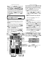
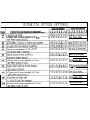
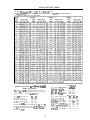
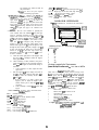
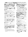
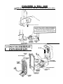
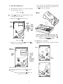
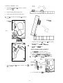
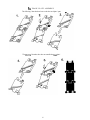
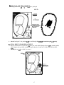
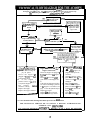
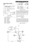
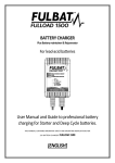
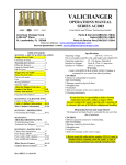
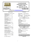
VALICHANGER
OPERATIONSMANUAL
SERIESAC6000/6001/6002
American Changer Corp.
4710 NW 15’h Ave. Bldg. 5
Ft. Lauderdale, FL 33309
Parts & Service:(888)741-9840
Sales:(800)741-9840
Fax:(954)772-5248
Internet Address:www.americanchanger.com
SECTION A: SET-UP AND INSALLATION
Uncrating & Setup .................... 3
Fill@ the Hoppers .................
3
Using the Dump Mode .............. 3
DIP Switches. ........................ 3 & 6
Hopper Pay out Table ............. 4
Bonus Pay Out Table. .................5
Fuses ................................... 6
About the hopper/Coin sizes ......... .6
Indicator Lights.. ..................... 6
NEW HOPPER ERROR CODES . ..7
Functional Descriptions. ............ 7-8
Wiri”g defmitions.. ................. 8
SECTION B: VALIDATOR
INFORMATION
.,8-l 1 ’
CoinCo Validator information ........ .
Cleaning the coi”c0 ................. .9
Setting the CoinCo dip switches...1 0
Clearing a bill jam in the CoinCo.11
SECTION C: COIN HOPPERS
INFORMATION.. ................... .12-18
SECTION D: TROUBLESHOOTING
INFORMATION. .....................19-21
Troubleshooting Guide ................19
Technical Flow Diagram ..............20- 2 1
SECTION E: PARTS LISTS
Cabinet Parts Breakdown., .......... ..2 2
Parts Coin Control Hopper MKIV .. .23
Parts CoinCo Bill Validator ........ ..24-2 7
CoinCo 6mncheS and Service centers
are on the back cover of this manual.
Rev. TRPL”RC” Nov.98
Specifications
Operati”g voltage
120VAC+lO/-15 %
Power consumpt.(controller only, add hoppers and
validator) 1 Ow
Operating temperature
32 130 degrees Fahrenheit
Interface to Hoppers
24vdc & 12vdc 1.5 amps nux.
Interface to Validators
120vac .5 amps max.
Warranty
CoinCo BA30B - BA30BB Validator
The Coin’& BA30B BA30BB Dollar Bill Validator is
warranted for two years from date of purchase.
COVERED
Ji Defect in workmanship or material.
NOT COVERED
f Damage caused by physical abuse.
Y Misapplication.
Y Vandalism.
H End “sers attempt, on his own to repair iteni
$ Clea”i”g maintenance.
It is the End User’s responsibility to follow cleaning
maintenance procedure outline on page B-2. Any unit coming in
for repair requiring only a cleaning will be charged a flat rate of
$35.00 plus shipping and handling.
i
Dispensing System and Logic Board
The dispenser and logic boards are warranted
for one year fro& date of purchase,
COVERED
v Defects caused by material “I wor’ananship.
NOT COVERED
Y Damage caused by physical abuse.
Y Misapplication.
f Vandalism.
Y End Users attempt, on his own to repair.
A Return material authorization number (RMA#) must be
obtained before returning a unit for repair. A copy of
invoices must accompany any and all warrantee work.
UNCRATING AND SET-UP
Remave your Series AC6000-6002 changer from the
shipping box. Open the door. (The T-handles are e screw-in
&pe and therefir, musk be fumed at leas! IO times counterclockwise unlil il opens.) Inspect for any ConneCtOTs Or
components that may have been dislodged during shipping.
The lock and keys for your changer will be inside the manila
envelope along with this manual. To install the lock, insert
the cylinder into the round hole in the middle of the T-handle
and push until it stops. Now turn the key and lock until you
hear it “snap.” Turn the key counter-clockwise % turn and
remove the keys.
The only way to get a duplicate set of keys
made is to save the red tag that comes between the
,keys. This ID # starts with ACC
KOTE:
FILLING THE HOPPERS
When each hoppers has less than 80 . 100 coins left the red
“Empty” LED will light on the front of the changer. If you
have disconnected your LED make sure the orange wire is
going to the terminal on the LED that has the red positive
mark next to it. \hhcnever the “Empty” LED is “ON” the
validator is disabled and it will no longer accept bills.
1. Turn OFF the power on the main logic board.
2. Pour the coins into the large opening in the funnel on
the top. There mat be nf leas1 enough coinr fo cover
t h e two g o l d ploter of the bottom of the hoppers.
(Somewhere between 160 and 17,000 coins minimum
to maximum.)
3. Turn “ON” the power switch. The “Empty” LED is
now off and the bill validator is ready to accept bills.
1.
TEST:
Before permanently installing the changer, do a functional
test to verify that there is no shipping damage to your new
changer(s).
2.
3.
4.
Extend the power cord through the hole in the back of the
changer or the bottom and plug it into a grounded IZOwc
outler. The dip switches are already set for a 4 coin per
dollar pay-out of the hoppers, and the Bill validator is
ready to accept $I-$5-$10.SZO dollar bills.
5.
Fill tbe each hopper with at least 100 coins. On the main
logic board rum the switch on the bonom right comer “ON”.
(SEE FIG. 1 ON PG.3) The rocker switch has a “I ” and
“0” printed on it. When the “I ” is pressed down the
changer is “ON”.
__.__._^_.___..._
-
BILL
METER
‘I
USING THE DUMP MODE TO EMPTY THE
HOPPERS
Open the cabinet door.
Turn OFF the POWER switch.
Place a suitable container in front of the hoppers to
catch the coins.
Press and hold the “DUMP” button on the upper right
comer of the Main Logic Board. Turn ON the Power
switch. The red LED numbers on the main logic board
will come on all “88888’s” then go all “00000’s”. Once
the red “00000’s” light up, release the “DUMP” button.
If it is not released within wo seconds, the “DUMP”
mode is canceled as a security feature.
The hoppers will dispense coins until the POWER
switch is turned OFF. If the red LED numbers are not
counting up rapidly on the Main Logic Board‘s display
the dump mode was not accessed. Please try again.
THE DIP SWITCHES
The AC6000-6002 series changer is capable of dispensing
coins in different pay opt modes. Sating the coins out per
dollar is controlled by which Dipswitches turned “ON.”
(Refer to figure I for their location.) For example. switch #2
is “ON” on both dipswitches; therefor the payout equals 4
coins per dollar. Two coins per hopper for one dollar.
._-.- ‘T THE DIPSWITCH BANK FOR SETTING
~THE BILL DENOMINATIONS.
(For those dip switches go to page IO.)
IFUSE
1
l&D INPUT I
DIPSWITCH OPTION SETTINGS
4 Tokens with a bonus payback in $1 incr.
(See bonus table.
I
1 Set in $1 increments
I
ISee bonus table.
I
lo lo lo lo lo lo lo lo
ISee bonus table.
I
(See bonus table.
I
BONUS PAY-OUT TABLE
ALL CALCULATIONS ARE BASED ON THE TOTAL COINS YOU SET FOR THE $1.00 BILL
For Mode #8, dirregard the % sign. (I.e. %2 = 2 tokens not $2 ilr tokens.)
THE FOLLO\h’fNG BONUS OPTIONS ARE CONTROLLED BY THE RIGHT DIP SWITCH ONLY!!
“NO” MEANS “NO BONUS” FOR THIS BILL.
Another way to look ut the Bonuspay out
mode is as follows:
The bonus is paid out by the amount of tokens given for a
dollar. For fhe below explanation we will say you are giving
4 tokens per dollar. Left dips #3-#6-#7 is ON.
Right dipswitch
For a S5.00 bonus payout:
#I
112
OFF OFF
20 tokens + no bonus
20 tokens + 4 extra tokens
ON OFF
20 tokens + 8 extra tokens
OFF ON
20 tokens + I2 extra tokens
ON
ON
For the $10.00 bonus pay first double the pay out for the S5
bill. So if the total tokens given for the 55 bill was 24, the
pay cut for the SIO bill is 48 tokens. t&v let’s figure out the
bonus for the SIO bill.
Right dipswitch
#3
#4
OFF OFF
ON OFF
OFF ON
ON ON
Right dipswitcb
For a 520.00 bonus payout:
#S
#6
#7
OFF OFF O F F
SlOpayout+nobanus
ON OFF OFF
510 pay out + 4 extra tokens
O F F OK
OFF
510 pay out + 8 extra tokens
OFF
SIO pay out + I2 extra tokens ON
ON
OFF ON
510 pay out i I6 extratokens ON
S IO pay out + 20 extra tokens OFF ON
ON
ON ON ON
S IO pay OUI + 24 extra tokens
For a $10.00 bonus payout:
SSpayout+nobonus
55 pay out + 4 extra tokens
SS pay out + 6 extra tokens
55 pay out + 12 extra tokens
The following table shows how to set the dip switches to
your desired payout.
“Oh”’
COINS PER DOLLAR
#I
1
#2
2
$3
4
#4
8
If you want to dispense 5 dimes and 2 quarters per dollar turn
“Oh”’ switches #2 on the left and #land #3 on the right dip
switch. (2 quarters + 5 dimes = $1 .OO)
Indicator Lights
Main Logic Bonrd.~
1. Green LED on: AC power applied to the logic
board. All fuses are good.
2. Decimal Point:
A. H&bear 5 and 12vdc present. The changer is in
standby waiting for a bill pulse.
B. On Steady Out of service, Hopper error detected.
Validam /ogic board:
1 . RcdLED
A. On Steady Standby h4ode, waiting for bill
l”XTt!O”.
B. Flashing - Error mode, go to page for error code
informarion.
C. Off - The changer “Empty” LED is lit.
The kft dipswitch controls the left hopper’spay out and the
right dipswitch controls the right hopper's pay auf
Refer to the next table to set up your changer for the settings
you need.
FUSES
Hieh voltaee fuse: This ir the primary transformer AC fuse
for the main logic board and the validator. Any direct shoti
of the Transformer or validator will cause this fuse to blow.
Replace this fuse with a 2-N amp AS fuse only.
REPLACING THIS FUSE WITH ANYTHING OTHER
THAN A 2 % AMP ‘AS” MAY RESULT IN A FlRE OR
AN UNSAFE WORKING CONDITION!! (See fig. 1 for
1
Coin counting 1
LED.
Hopper coin
bin. (Dump
the coins into
this hole.
1600 coins
location of this fuse.)
Security LED.
Low voltaee fuse: This is the secondary transformer fuse for
(all
systems OK)
the 5 28 vdc sections of the main logic board and hoppers.
It is located to the left of the transformer. (See tig. 1)
Replace this fuse with a 2-s amp AS fuse only. L2vdc Power LED.1
REPLACING THIS FUSE WITH ANYTHING OTHER
THAN A 2 % AMP “RS” MA Y RESLJL T IN A FIRE OR
AN UNSAFE WORKING CONDITION!!
Coin Control Hopper MKIV
Three green LED indicators are fitted on the hoppers and are
visible in the section where the coins exit the hoppers. From
left to right these are designated as follows:
1. Logic power supply on (12 & 24vdc present).
2. Security optical obstruction indicator -. Should be “on”
when unit is OK.
3. Output indicator, indicates coin passing photo-sensor.
This is the optical sensor the coin will obstruct on its
way out of the hoppers. For normal operation LED # 3
will be off until coins are dispensed.
coin counting optic.
1
l-l
12 pin male
connector.
(located on the
1 bpposite side.) j -
I
CoimToken Sizes
The hoppers will automatically adjust to dispense
coins/tokens in size from 20-30 mm in diameter and I .25
3.5 mm in thickness.
The right & lefi homer has a
removable coin chute installed.
There is an option available to dispense smaller coins.
A nickel is approximately 21 mm a quarter is approximately
25mm A Susan B. Anthony is 28mm
6
I
I
I
I
LOGIC BOARD ERROR CODES
6.
The EPROM then sends the hopper pulses out pin #23
to pins 6 and 7 of the red 12 pin hopper plugs. These
pulses travel through the purple and brown wires of the
hoppers wire harness to the hoppers pins 8 and 12.
1. The hopper turns itself on with the first hopper pulse.
The hoppers counts the hoppers pulses sent from the
EPROM chip on fN3 (pin 12) while dispensing the
coins at the same time. when the amount of hoppers
pulses in equals the coins dispensed through the coin
counting optical sensor the hopper turns itself off.
8. The Changer returns to the standby mode with the
decimal point flashing once per second until another bill
is inserted.
We now have the ability to display error codes in dealing
with the problems associated with the changer. There are 2
different locations error codes can be displayed depending on
the source of the problem.
If the “Empty” LED on the outside of the changer is lit:
I. Press and hold in the “Dump” button on the main logic
board.
2. The display now shows the code for your problem.
NOTE: THE METER ON THE MAIK LOGIC BOARD
CANNOT BE RESET TO ZERO!!!
Functional Descriptions of Out-of-Service Conditions
Error Codes
01 = Low Coin
02 = Coin exit window is blocked
04 = Under-payment was detected
10 = Over-payment was detected and
prevented. (Jackpot condition)
1.
A “03 ” error code is a low coin and eril blocked in the *ame
hopper.
Functional Description of the Series AC6000-6002
Changer
the hoppers with coins and turn the changer on.
2.
I.
2.
3.
4.
5.
When power is applied the validator will cycle twice,
the out-of-service LED flashes then goes out, the green
LED on the main logic board comes on steady, and the
decimal point on the main logic board number display
will flicker on once per second in the standby mode.
During the power-up mode the main logic board relay
clicks twice enabling power (IZOvac) to the validator.
When this relay is not enabled it routes 12vdc ground to
the out-of-service LED. Without power to the validator
the changer cannot accept hills. Since we are not in the
error mode, the red LED on the validator logic board is
on steady.
When a bill is inserted into the validator bill slot, the
bill will be pulled inside. The validator then compares
what the bill looks like to its memory. After the hill is
validated it grounds the 5vdc lines causing a pulse along
the yellow and blue validator harness wires to pins 5
and I5 of the main logic board. Each pulse stands for
the amount of the denomination validated. (i.e. I pulse
for % I, 5 pulses for $5).
The 5vdc pulse then travels from pins 5 and I5 to the
EPROM chip (ver. TRPL-L) pin #25. The EPROM
sends a 12vdc pulse to the meter chip (US) out pins #21
8; 22 (one pulse per denomination validated ).The
EPROM also multiplies the bill pulse by the DipSwitch
settings (The EPROM reads the DipSwitch settings
during the power up mode and stores them into
memory.)
7
Blown Fuse: an AC power spike in line voltage or a had
transformer on the main logic board can cause A blown
fuse on the main logic board. If either fuse blows the
indication is the green LED on the main logic hoard will
not light.
A . I&place the fuse. If the green LED DOW lights then
there was a spike.
B. If it does not and the fuse blows again the power
transformer is shorted. To test the transformer use a
voltmeter set for ohms and measure across the
primary (400hms) and the secondary (I .Sohms).
Hopper Fault: A hopper fault can either be a jammed
hopper, a blocked coin counting optic or a bad hopper
logic board.
A. Indications for a jammed hopper are the changer
accepts bills, the meter counts up, but nothing or
not enough coins are paid out.
1. After 2 minutes the EPROM shuts off the
validator if the coins are not paid out
correctly. The “Empty” LED will flash once
per second.
2. At this point the three options open are to
attempt repair on your own, call your
distributor, or return the defective hopper to
American Changer.
B. Indications for a blocked coin optic or bad hopper
logic board arc the out-of-service LED on the
outside of the changer is lit and the red LED on
the main logic board is lit and flickers off once
per second.
1. If two of the 3 green LED’s on hopper IO&Y
hoard are lit then the hopper logic hoard is
bad.
2.
If there is a coin or foreign object caught in
the coin exit window LED’s #I and #3 will
he lit on the hopper logic board instead of
LED’s #I and #2.
a. Take off the side of the hopper with
the 5 Philips screw?. Pull up on the
Yellow - Raw sensor output line.
Purple - Hopper pay out line from main logic board (+).
B r o w Hopper pay out line from main logic board (-).
Red +lZvdc logic board supply voltage.
Black(s) -IZv, 24~ low coin sense ground.
Orange i24vdc Motor supply voltage.
exit window logic board and look for
the jammed item.
b. Ensure you have the pins aligned
before reconnecting logic board.
3. Validator Fault: When a validator fault occurs the
ralidator’s EPROM shuts down the valid&x and
flashes an error code via the red LED on the validator
logic board. When there is no error this LED is on
steady. The vabdator only gives bill pulses to the main
logic board so the main board never knows if the
validator isn’t functioning. Therefore the out-of-serviceLED will not light. (See page 7 for validator error
VALIDATOR INTERFACES
18 PIP INTERFACE CONNECTOR DETAILS
CodeS.)
4. Low Coins: The low coin condition is probably the
most common fault. The EPROM on the main logic
board is constantly checking for low coins in the
hoppers. This is done with a low current 5vdc signal on
pin #3 of the hopper’s output connector. The voltage
then travels down the hopper’s wire harness on the
white wire to pin #7 of hopper’s plug. The signal is
applied to one of the gold low contact plates at the
bottom of the hoppers. The 5v travels through the coins
through the other contact gold plate to hopper’s pin #2.
It then goes through the black wire in the hopper’s
harness to pin #IO on the main logic board. Any
interruption of more than l/2 a second will cause an outof-service condition.
A. Clean the bottom gold plates of the hoppers with
steel wool or fine sandpaper. Refill the hoppers
and try again.
B. Check continuity, (0 ohms) resistance, from pins 3
(white) and IO (black) of the red hopper harnesses.
Make sure both hoppers are full and the changer is
turned off.
1. If the continuity is 0 ohms, replace the main
logic board.
C. Pull the hoppers out of the changer, then look at
the 12 pin black male connector that sticks out of
the hoppers. Place the continuity checker’s leads
on pins 2 & 1.
1. If the continuity is 0 ohms, replace that
hopper’s plate or adjust the hopper’s plate
female socket’s pins so that they are not so
spread out.
2. If the continuity is infinity, then replace that
hopper.
WIRE HARNESS COLOR AND DEFINITIONS
Validam harness:
Switched Hot IZOVAC.
Red
White - Neutral IZOVAC.
Black - IZOVAC Low current validator enable.
Y e l l o w +Svdc credit pulse line.
Blue -5vdc credit pulse line.
orange - +lZvdc Empty LED.
B r o w n -12vdc Empty LED.
Hopper Harness
Coin counting optic status line.
Gray
White. Low coin sense (+5vdc).
G r e e n Coin counting optic pay out feedback line.
I IPin #IO
Interfacing the Man 2501 Series with the ValiChanger
S-Position Switch
I
off
2
3
4
5
6
0”
off
on
off
an
off
1
green & white go to the other wire nut
CoioCo BA30 Flash Codes
Flash codes l-6 may appear during normal servicing of the
BA30. To access flash codes 7.18, open bill box lid and
remove power from the BA30 for IO seconds. Reapply
power to BA30 with bill box lid open. Flash codes 7-18 will
now appear for respective error or condition detected in the
BA30. If more than one error or condition exists, the lower
number flash code will appear until its respective error or
condition is canected. The left and right sensors referenced
below are given viewing the BA30 from the front.
#of Flashes
Description of Flash Codes
Bill box full
I
Bill box lid is own or bill box is off
2
Check bill path’
3
All bill accept switches are off
4
Bill jam or sensor error
5
Stacker motoribome sensor
6
nansport motor/encoder sensor
7
For higher error codes or any other service problems call
our service deportmenl roilfree at:
(888)741-8940
8
BA30B (B) CLEANING IF ANY OF THESE PROCEEDURES ARE PERFORMED TO YOUR VALIDATOR
AFTER IT IS RETURNED UNDER A WARRANTY REPLACEMENT, YOU WILL BE SUBJECTED TO A
S35.00 LABOR FEE.
BA30B CLEANING AND hlAINTENANCE:
tiote: Perroleunr-hued c/ennerr andjreon-basedpropeNnnlr
can damage plastic and some elecrronic componentx.
Scouring pads and srl/i brushes may harm the protective
cor>formol coating on the circuit boards and can mar the
phsric. These items should never be used when cleaning the
BA30 bill acceptor.
The BA30 should be cleaned every 7,000 bills or every 4 6 months (or BE needed, depending 00 the environmental
auditions of the location). Dust can be removed with B
soft brush or cloth or it can be blown out using
compressed air.
Procedure:
I. Disconnect power from the bill acceptor.
2. Remove the bill box and use a soft cloth to wipe the dust
from around the intermediate frame and stacker plate.
3. Remove the lower track.
4. Using compressed air or a soft brush, blow or brush the
dust off of the optic sensors and out of the recessed sensor
Ope”,“gs.
5. Remove dust from around the belts and wheels on the
lower housing and the sensors on the upper sensor board.
The upper sensors are located directly above the lower
housing sensor when the lower housing is installed.
6. The bill path can be cleaned to remwe further din and oil
usinc a soft cloth moistened with a mild soap and water
I
I
thoroughly b&e op.&@ power to avoid possible shock
hnrnrd. I/the srackerplate does not return to the home
position, remove power and carefdly remow the bill box to
ovoid damaging /he bill box and/or stacker plate.
4. Remove the lower housing.
5. Remove the bottom cover from the lower housing.
6. Run hot water (1101/4-140114F) over the lower housing
from the top and bottom. Using a soft brush, gently
clean any residual salt. Use a soft absorbent cloth to
clean a n y residue off the lower housing. If the
transformer gets wet, allow the unit to dry for 24 hours
before applying power.
I. Remove the front mask. Using hot water and a soft
brush, clean the front mask, upper sensor board, main
frame anti-pullback levers and position sensor mount.
Caution, The motors ore not protected/ram water, therefore
the unit must be held in n manner that prevents walerfrom
running over the intormediotefiame crossbar.
8. Remove rhe position sensor cover on the crossbar and
co@dly lift the LED&m its mount. (Early models only.)
Caution: Protective coating on the LED leads should nor be
dunaged. C/can all snl? residue from the mount. sensor hole
and detector area.
The detector con be seen through the sensor hole, and is
iocared in the chassis. Replace the position sensor cover.
(Early mod& only.)
9. Verify that the anti-pullback levers move freely and that
the spring returns them to their open position.
IO. Allow the unit to dry thoroughly.
11. Clean the magnetic head using a swab and isopropyl
alcohol.
I?. Replace the front mask
13. Replace the lower housing cover.
14. Replace the lower housing into the main frame.
15. Remount the bill box.
16. Apply power and insert bills to verify that the unit is
functioning properly.
6 OR 7 ERROR CODE FLASHES
The cleaningprocedurefor this common occurrence is listed
below Just follow these s,qx.
1. If this &de has occur&d on a new machine or one that
the validator’s DIP switches were just changed, Ensure
that all the white plugs on the side of the validator board
away from the red LED are plugged in securely.
2. Remove the bill box.
3. Turn the changer ON then OFF in an attempt to stop the
metal push plate so that it COASTS into the fully
outward position.
4. Using an air compressor or a can of compressed air
blow out the area behind the push plate until if IS
completely free of all dust and lint.
5. Turn the changer power back on so that the push plate
returns to the inward position. If the same error code
persists. repeat steps I - 3 concentrating on the top
center area behind the plate.
6. Replace fhc bill box.
d”b0”.
7. Clean the magnetic head using a swab and isopropyl
alcohol.
8. Once the lower housing is dry, place if back into the
mainframe so that the tab on the bottom locks into place.
9. Blow the dust out of the encoder wheel and its &XL. (It
may be necessary to extend the stacker plate to access the
encoder wheel. Supplying power to the unit momentarily can
do this, so that the stacker plate extends.)
10. Remove dust from the transport belt areas and from any
other places of build up.
I I. Remount the bill box.
12. Apply power and insert bills to verify that the unit is
functioning property.
BA30 CLEANING PROCEDURE FOR SALT WATER
POLLUTED UNITS:
Note: Petroleum-based cleaners andfreon-basedpropellants
con dnmoge plastic and some electronic components.
Scouring pads and stiff brushes may harm the protective
ro&mol coa,iog on the circuil boards and can mar the
plastic. These items should never be wed when cleaning the
BA30 bill occeplor.
Procedure:
1. Remove power from the bill acceptor.
2. Remove the bill acceptor from the vending machine.
3. Open the bill box lid and verify that the stacker plate is
in the stand-by/home position. If it is not in the home
position, apply power and observe that the stacker plate
returns home.
9
HOW TO SET-UP THE BILL VALIDATOR FOR ACCEPTING SPECIFIC
BILL DENOMINATIONS. (I.E. $l.OO-$5.00~$lO.OO-$20.00 DIP SWITCH
LOCATIONS)
YOU MUST REMOVE THE BILL
BOX IN ORDER TO STICK A
SHARP THIN OBJECT INTO THE
SLOT TO CHANGE THE
DPSWITCH SE’M’lNGS.
B
0
T
T
0
M
BA30BIBBIBAB Option Switch Settings
SWITCH
I
2
3
4
5
6
7
8
ON
High Security
Accepts bilk in one
directions only (face
up, green seal first)
Standard credit pulse
150mson 150msoff
$20 Accept
$10 Accept
165 Accept
$2 Accept
$1 Accept
OFF
Standard Acceptance
Accepts bills in both
directions (face up)
Short credit pulse
50 Ins on 50 Ins off
$20 Reject
$10 Reject
S5 Reject
$2 Reject
(61 Reject
10
CLEARING A BILL JAM
I”5” ERROR CODE FLASHS ON THE BILL VALIDATOR STATUS LED.)
I
EXPLOI)JW VU w
I
---w
P
MKIV UNIVERSAL
HOPPER
INDEX
PAGE
SERVICE MANUAL
1. Coin box removal & reassemble.
12-13
2. Exit window replacement.
13
3. Logic board replacement.
14
4. End plate removal.
14
5. Track plate removal.
14
5a. Track plate assembly.
15
5b. Track plate replacement.
I6
5c. Final drive gear replacement.
17
6. Gearbox assembly.
17
7. Motor replacement.
17
To w-jam the hopper, refer to sections
4 - 5b, pages 14 -16.
7.
1. COIN BOX REMOVAL
1,
Place the hopper in front of you as shown, (looking at
the outside of the ‘coin box’).
As the ‘coin box’ is being removed, carefully slide the
‘logic board’ out. The stirrer may stay with the ‘coin
box’ or fall onto the center plate.
Refer to FIG 1,
2.
Remove the 2 locking nuts, which hold the ‘low level
sense plate’ wires to the studs.
3.
Remove the crimp & wire from the studs.
c
WI, LOCKING
NUI
f
STUD
ACCESS IS NOW AVAILABLE TO THE ‘LOW
LEVEL’ SENSE PLATES, THE MAIN PCB, THE
EXIT WINDOW, THE MOTOR TERMINALS &
PART OF THE WIRING LOOM.
Refer to FIG la,
4.
la. COIN BOX ASSEMBLY
Remove the 5 screws indicated (B), which hold the
‘coin box’ to the ‘center plate’.
Refer to FIG Ib.
6.
Gently lift the ‘coin box’ away from the rest of the
hopper.
NOTE:- The ‘logic board’ & ‘stirrer’ are
located in the ‘coin box’.
13
1.
Firstly, locate the ‘stirrer in the ‘coin box as shown in
FIG 12.
COIN BOX ASSEMBLY (cont.)
2.
Line up the ‘centre plate’ Kr ‘coin box’ as shown
below. FIG 12a.
3.
Route the ribbon cable as shown below.
4.
Fit the ‘logic board’ into slots shown below.
5.
Feed the level sense wires through the slot shown
below.
FIG 12c
FIG 12a
Ribbon
7.
Align the ‘center plate’ & ‘coin box’ & push together.
8.
Turn the hopper OWI & refit the screws.
9.
Refit the level sense wires
slot
2. EXIT WINDOW REPLACEMENT
1. First, remwe the ‘coin box’, section 1.
This will then enable access to the ‘exit window’
2. Unscrew & remcwe the 2 fntig screws. FIG 4.
3. Remove the ‘exit window’ from tix ‘center plate’.
4. Unclip & remove the lo-way ribbon cable header.
6.
Lift the ‘cent~e plate’ to meet the ‘coin box’. FIG 12b
&c.
5.
14
To re-assemble, follow the above steps in reverse.
F’G6’ 7
3. LOGIC BOARD REPLACEMENT
1.
rl
First, remove the ‘coin box’, section 1.
This will then enable nccm to the ‘logic board’.
9ofl
/
COIN
EXIT
FIG 5.
s,onwng
plofe pas 2
[ADMCENT)
5.
NN 2
LOGIC BOARD
lo-way ribbon IDC socket (CONN 1).
2.
3.
4.
5.
6.
I.
8.
Move the two ejector arms at right angles to & away
from the connector, if fitted.
This should release the socket from the header.
Clasping the connector between thumb & forefmger,
pull away from pin header.
14.way crimp socket (CONN 2).
Gently, unclip the “friction lock” from the connector
housing.
Clasping the connector between thumb & forefmger,
pull away from pin header.
The Logic Board is now released.
To reassemble, follow the above steps in reverse.
4. END PLATE REMOVAL
1.
Place the hopper in front of you as shown, (looking at
the outside of the ‘end plate’).
Refer to FIG 6.
2.
Remove the 9 screws indicated (B), which hold the
‘end plate’ to the ‘center plate’.
3.
Locate the position of the ‘connector blanking piece’.
4.
Holding the ‘connector blanking plate’ gently lift the
‘end plate’ away from the rest of the hopper.
15
s\onring
plate pa I
lOPPOSlIE)
l
To re-assemble, follow the above steps in reverse.
5. TRACK PLATE REMOVAL
1. 1. First, remwe the ‘end plate’, section 6.
See FIG 7.
2 . The ‘elevator track’ & ‘foal drive gear’ can now be
removed by lifting up & away from the ‘center plate’.
Final drive ,,.,_
gear (Plasti::::
5a. TRACK PLATE ASSEMBLY
The following 3 sketches show how to take the ‘track plate’ apart
The fdowing 3 sketches show how to assemble the ‘back plate’.
16
5b. TRACK PLATE REPLACEMENT
1. The gray shaded area, in FIG 7b, is the ‘track plate’ guide path,
FIG 7b.
to centre plate
2.
Once the ‘hack plate’ is in position, lam the track through 720 ’ to enswe it is seated in the guide path correctly
5. FINAL DRIVE GEAR REPLACEMENT
1. Once the ‘elevator track’ is in place, the ‘foal drive gear’ can be fitted by placing the gear wer its mounting spindle,
while lining the teeth up with the secondary drive gear, adjust the ‘elevator track’ so that the gear falls into place.
FIG 7~.
2. The end plate can ILOW be re-fitted. See section 6
FIG 7c.
Final drive
gear (PlOstiCI
17
6. GEAR BOX ASSEMBLY
1.
Remove the end plate. Section 6.
2.
Remove the ‘elevator track’ & ‘fmal drive gear’.
Section 7.
3.
Remove the gearbox cover. Section 8.
4.
Remove the gears in the order as shown in FIG 9.
access to the motor fixing screws is now possible.
5.
To re-assemble, follow the above steps in reverse.
FIG 9.
FIG
7. MOTOR REPLACEMENT
1.
Remove the ‘coin box’. Section 1.
2.
Unsolder the red & black wires from the motor.
NOTE: The black wire connects to the terminal
marked with a RED dot.
3.
Remove the ‘end plate’. Section 6.
4.
Remove tbe ‘track plate’ & fmal drive gear. Section
7.
5.
Remove the gearbox cover. Section 8.
6.
Disassemble the gearbox. Section 9.
7.
Unscrew the 2 motor fixing screws. FIG 10.
8 . To re-assemble, follow the above steps in ~e”erse
18
NOTE: Before starting this procedure ensure the changer is plugged in, the ON/OFF switch is on,
the hoppers orefull of coins, and aI wire harnesses we connected securely and correctly.
Thr wires exiting the red connectors shouldpoint awayfrom the board.‘!
Start here !!!
Is the “Empty” LED
o” the front of the
machine lit?
\rrf
-.
on the main logic
board?
YES
and clean the
Will the valid&or
accept a bill and stack
it in the bill box?
, IY”
Wilt the validator try to 1
pull in a bill then reject it?
NO
YES
Does the meter on
the Main Logic
1 Board count ;p? 1
.
If fuse blows again
replace the Main
Logic board.
1.
2.
NO
Replace the bill validator.
Replace the bill validator wire harness.
(Check the yellow&blue wires)
I
+
The validator logic
board is flashing
an error code.
Refer to pg. 9 for
code definitions.
“wq
YES
,
.
_I
weiving the bill pulses but the
hoppers are not receiving the
pay out pulses.
E n s u r e t h e h o p p e r s ar’
plugged in fdy in the bacl
to the hoppers plate.
One
of
tbe
hoppers
i
jammed. Refer to pgs.22-2:
to repair the hoppers.
hames~
The
hopper’s
connector is faulty.
Replace the hopper.
Replace the hopper’s harness.
I
The main loeic board is readine a
hoppers hard fault or a “Nohoppers found” fault.
1. Ensure the hoppers are plugged in
firmly in the back to the hopper’!
plate.
2. Ensure that the left and center
green LED’s on the hoppers are
lit.
3. If the left and right green LED’s
are lit then something is jammed
in the hopper’s exit window. See
page to clear the jammed object.
4. Replace tbe hopper.
5. Replace the hopper’s harness.
6. Replace the main logic board.
.-..,
a low e& indication.
Make sure the hoppers are
plugged securely into its
connector.
Clean the gold low contact
plates located under the coin
with steel wool or a fine grit
sandpaper.
Make sure the female
connector on the hopper’s
plate is not broken OT being
pushed out the back of the
hopper’s plate.
Go to the next page and
follow procedure “BY
‘or a more detailed trouble shooting information proceed to the next section!
FOR TECHNICAL SERVICE OR TO OBTAIN A RETURN AUTHORIZATION
N U M B E R C A L L (888)741-9840
A N Y R E P A I R R E T U R N E D WlTHOUT A RETURN AUTH. # WILL BE REFUSED!
19
-!
Solution:
5.
6.
7.
6.
Ensure the changer is plugged in.
Ensure the on/off switch is rocked to the (I) position !down).
Unplug the female end of the line cord from the main logic board AC
connector and plug it in again tightly.
Measure the AC voltage at the outlet or check the breaker/fuse box.
You can also plug another item into the AC wall outlet to fnsure there
is power prescnr at the outlet.
Inspect the AC line cord for cuts OT abrasions.
Check both fuses on the Main Logic Board.
Replace the main logic board.
Replace the line cord.
I.
Ensure the hoppers are not out of coins. (There should be enough
I.
A. The changer is
completely dead. (The
green LED on the main
logic board is not lit.)
B. The “Empty LED is lit.
The decimal point on the
light-up number display is
“off’ more than it is “011”.
2.
3.
4.
2.
3.
4.
coins in the hoppers to cover the gold low level contact plates
approximately S30-$40. These plates are located at the bottom of the
hoppers where you Pour the coins.)
Check the hoppers wire hamess that extends from the back of the plate
that the hoppers slide in and out on for chipped pieces or other
damage. (Pay close attention to pinr# 2 & 7.)
Clean the gold contact plates with steel wool.
Perform the following steps:
Turn the change; off.
A
Ensure the left hopper plate red connector on the left side of the
B
main logic board (MLB) is plugged into the bottom connector,
and the right is plugged into the top connector.
C On the MLB slide all the dipswitches left to the “off’ position.
D On the left DipSwitch slide #3 “ON” enabling a 4 coin per dollar
plyOUt.
On the right Dip switch slide #8 “ON” disabling the top hopper
connector and enabline the changer into the”One Hostler
1. Mode”
F. Turn the changer on. _
G If the “Empty” LED on the front of the changer is now off,
remove the right hopper and service this hopper. The changer
will function in this mode until the hopper is fixed.
H If the “Empty” LED is still “on”, turn the changer off and switch
the hoppers, and turn the changer back on.
If the “Empty” LED on the front of the changer is now off,
I.
remove the right hopper and service this hopper. The changer
will function in this mode until the hopper is fixed. Remember IO
remove the coin chutefrom the hopper or ihe coins will/a/l into
the changer instead of into the coin cup!
If the “Empty” LED is still “ON”, turn off the changer.
1.
K. Reverse the hopper’s plate connections, (top to bottom, bottom to
top), and repeat steps F thru I. Keep in mind that you are
trouble shooting the Hopper Plates instead of the hoppers
Replace the Main Logic Board.
Replace both hoppers.
Replace both hopper plates with the harnesses
E,
5.
6.
7.
C. The “Empty LED is lit.
The decimal point on the
light-up number display
is “on” more than it is
“Off’.
I.
2.
Ensure the hoppers arc pushed into the hopper’s harness on the back of
hopper plate tightly.
Ensure that left and center green hoppers LED’s are Iit only. Not the
left and right LED’s. If this is the case go to pg. 20 to w-jam the
hopper exit window.
20
PROBLEM:
D.
The green LED on the Main
Logic Board is lit but the
Light-up display does not.
E. The bill validator accepts
and stacks the bills, but the
meter does not increase.
F. The bill validator accepts
and stacks the bills, and
the meter does increase.
G. The bill validator will not
pull in the bill and the
“Empty” LED is not lit.
SOLUTION:
1.
2.
Bad 5 or 12vdc regulator on the main logic board.
The hoppers are shorted.
3.
4.
Replace main logic board.
Replace hoppers.
1.
Cheek continuity and for pin damage to the blue and yellow wires
on the validator harness.
Replace the valid&r wire harness.
Replace the validaror.
2.
3.
1.
2.
3.
4.
1,
2.
3.
4.
5.
H. The bill validator pulls in
the bill slightly then
rejects it.
I.
The bill validator red
status LED flashes a “5”
error code.
1.
2.
3.
1.
2.
3.
Ensure the orange wire going to the “Empty” LED is connected to
the + OT the terminal with the red mark by it.
Check for 12vdc going to the orange and brown wires. Ifthere is,
replace the LED.
Replace the main logic board.
Replace the bill validator.
Reolace the valid&x wire harness.
Clean the validator. (p&IO)
Remove the lower housing (pg. 12) of the bill validator. Ensure the
center wheel spins freely. Push snaight down on it slightly to
loosen.
Replace the bill validator.
Clean the validator optic LED’s (See pg.10)
Ensure that all the wire harness plugs are plugged firmly into their
white female sockets.
Turn to the back page of this manual and check for a Coin
Acceptors branch in your area to repair your bill valid&or
Take the bill stacker off the bill validator. Cycle the power on 1 off
using the switch on the main logic board and coast the silver push
bar so that it stops in its fully extended position. Blow out the area
behind the push bar with high pressure or canned air. Concentrate
on the encoder wheel in the area top center behind the push bar.
Turn to the back page of this manual and check for a Coin
Acceptors branch in your area to repair your bill validator
J. The bill validator red
status LED flashes a “6 or
7” error code.
K. The bill validators red
status LED is on steady
but it still will not accept
the bill.
Ensure the dip switch settings are still correct. (#3 “ON” only)
Check the continuity of the brown and purple wires on the hoppers
wire harness.
The hopper is jammed. Go to pgs.22-25 to u-jam the hoppers.
Replace the hoppers wire harness.
I.
2.
Pull our the lower housing, see page 12, and look for something
obstructing the bill path. (i.e. gum, papers. tickets, coins, etc.)
Look inside the Plexiglas case on the side of the bill validator.
Ensure that all the wire hamess plugs are plugged firmly into their
white female sockets.
21
PARTS LIST FOR THE AC60001600116002
c”
#3
PARTS LIST (SHOWN ABOW?)
1. AC6010
2. AClOlO-07
3. AC1040
4. AC2060
5. AC6081
6. AC1093
7. AC5080
8. AC9000
9. AC6065
10. AC2065.1
- CABINET COMPLETE WI COIN CUP (#2) & LOCK BRACKET (not shown)
- COIN CUP
COIN CONTROLS MKIV COIN HOPPER.
- MAIN LOGIC BOARD.
- FULL ‘CHANGE” FACE LEXAN FRONT (AC6082 TOKEN).
- LOCK AND KEY
- SCREW-IN T-HANDLE.
- COINCO BILL VALIDATOR.
-AUDIT BOARD (AC6001 & A&002’S ONLY!)
-QUARTER ACCEPTOR (AC6002’S ONLY!)
OPTIONAL PARTS LIST (ITEMS NOT SHOWN)
AC6010-03-LOCK BRACKET ASSY. WITH SILVER SQUARE NU’I
AC1040.3 -HOPPER PLATE WITH HARhESS
A C 1 0 5 1 - 2 OUTLET SURGE PROTECTOR
4 OUTLET SURGE PROTECTOR
AC1052
AC1091
- TILT ALARM ONLY
AC2010-10 -LEFT HOPPER CHUTE
AC2010-11 -RIGHT HOPPER CHUTE
-COIN MECH. ASSY.
Ac2065.1
22
COINCO PARTS LIST
MAIN FRAME
ITEM PART
NO. NO.
1
2
3
4
5
6
7
8
438-6
921361
921401
921492
921629
920807-2
921351
3456R6
24
DESCRIPTION
Nut & Lock washer 6-32
Mask Snack
SCEW
Frame Mount
Label, Bill Insert
Main Frame
Grounding Spring
Screw 5
COINCO PARTS LIST CON’T.
Item No.
1
2
3
4
5
8
9
10
11
12
13
14
15
16
18
19
20
21
22
24
Part No.
Descriation
902824-l
920823-2
407254-l
920000-3
407252
921387
407253-l
920834-l
920829-l
920823-3
920004-l
921403
92082 1-2
920889
920827
921128
920828
920040
920825-l
407246- 1
Hub, Transport Pulley
Pulley, Upper Transport
Gearbox Assy., Transport (includes #4), BA30BB
Wheel, Encoder
Stacker Assembly (includes #6 and #7)
Spring, Belt Tension
Gearbox Assembly, Stacking, BA30BB
Screw, Push plate Bearing
Pulley, Idler
Pulley, Lower Transport
Hub, Timing Wheel, ,670
Belt, Chassis, Black
Chassis, Upper Housing
Spring, Anti-Pullback
Clip. Upper Board
Clip, Wire
Lever, Anti-Pullback
Shaft, Wheel
Pulley, Inlet
Stacker Board, BA30BB
COINCO PARTS LIST CON’T.
ITEM NO.
;
3
4
5
6
7
8
9
10
11
12
13
14
PART NO.
DESCRIPTION
921704
921613
920949-2
920889
920X19-1
920818
920806-2
920003-l
920815
920040
920004-l
921055
345-4R4
407335
Bottom Cover
Transformer Holding Hose
X - former and Shield Assembly, BA30BB
Spring, Anti-Pullback
Mount, Anti-Pullback
Lever, Anti-Pullback
Frame
Pulley, Timing, ,870
Belt
Shaft, Wheel
Hub, Timing Wheel
Spring, Mag Roller
screw, 4x114
ShaR, Roller Assembly, Mag
26
COINCO PARTS LIST CON’T.
Item No.
1
2
3
4
5
6
7
Part No.
Descriution
921414
921179-2
3456R6
407383
921539
909729-2
407247-2
Cap Logic Board
Case, Logic Board
SCEW
Logic Board, BA30BB
Strain Relief, BA30BB
Label
Intermediate frame
S”ilP 139
Memph,r. TN 38132-2100
Phane:90,1345-2663
FM 9Q11345.3146
cad Feclea"
0orurs.n
3031 O"abeCSt..S"ite115
cauar.D: 752476719
~hanr:214/639-3910
iu(: 214fi38.3973
Phane:2M/779-1710
FM: 2Q4"W1105
BObChino"
Suits E
~,,ann.GA 30336-1639
Phone: IQ"6912117
FAX: 404/691-l416
ctwkcmckeP
Wd C.Srnirn
3R"l Maw
u sfwsEwlLLf.
a
a62 Ea9k me
~anxmilie.IL 60106-1980
Phane:WQf660-2650
FM: 63Q,660-3806
M,keD"rfC
JPWLW
18 TAMPA. FL
6,04 Be",u"i"RW
suite MO
,ampa.FL 336344406
Phom:aW249-7336
FAX: 813f249-1937
28