1
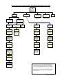
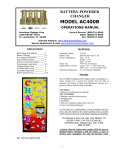
American
Changer
1400 NW 65TH Place ♦ Ft. Lauderdale, FL 33309
CLASSIC SERIES – CHANGER
OPERATIONS MANUAL
MODELS AC6000/6001/6003
ARL Listed STD: UL 756
AC6000 shown with “optional”
Token Marquee and Credit Card feature
Parts & Service: (888)741-9840
Service Fax: (954)917-5204
Sales: (800)741-9840
To order parts only, visit our website: www.americanchanger.com
Service Questions? E-mail:
[email protected]
Revised September 2010
Model Number:
________________________
Serial Number:
________________________
Tested By:
________________________
Date:
________________________
2
Specifications
Operating voltage
120VAC +10% to -15%
Power consumption
Controller:
Hopper:
Validator:
Operating temperature
32 - 130 degrees Fahrenheit
Hopper voltage & interface
24VDC, ccTalk Serial Protocol
Validator voltage & interface
24VDC, MDB or Pulse Protocol
Hopper coin capacity
100 minimum to 25,000 maximum
10W
48W Max
AE2602=50W Max
Warranty Information
A Return Material Authorization number (RMA #) must be obtained before
returning a unit for repair. A copy of invoices must accompany any and all
warranty work.
It is the end users’ responsibility to follow cleaning and maintenance
procedures as outlined in the validator manual.
Any unit returned for repair requiring only a cleaning will be charged a flat
rate plus shipping and handling.
Validators
Validators are warranted for two years from date of purchase.
Hopper(s) and/or Dispenser(s) and Logic Board
These items are warranted for one year from date of purchase.
COVERED
•
Manufacturers’ defects in workmanship or materials
NOT COVERED
•
•
•
•
•
•
Damage caused by shipping or physical abuse
Misapplication
Vandalism
End users’ attempt, on their own, to repair components
Cleaning and maintenance
Power surges and lightning strikes
3
Table of Contents
SECTION A: SET-UP & INSTALLATION
Setup
............................................
Mounting Instructions
.................................
Programming the Changer
Functional Description
5
5
...............................
6-17
.................................
17
Out-of-Service Conditions & Error Codes
Equipment Indicator Lights
.....................
17-19
..............................
19
Hopper Coin/Token Sizes & General Information
...............
20
....................................
20
Main Logic Board (MLB) Connector Pin Definitions . . . . . . . . . . . . . . .
21
Validator Interface
SECTION B: TROUBLESHOOTING INFORMATION
Technical Flow Diagram
.................................
22
Troubleshooting Guide . . . . . . . . . . . . . . . . . . . . . . . . . . . . . . . . . .
23-24
Maintenance Information
................................
25
SECTION C: PARTS LIST
AC6000/6001/6003 Parts List
............................
4
26
SECTION A
SETUP & INSTALLATION
Setup
Inspect for any connectors or components that may have been dislodged during shipping. The lock and
keys for your changer will be inside the manila envelope along with this manual and other pertinent
information. To install the lock, insert the cylinder into the hole in the middle of the T-handle and push
until it stops. Turn the key until you hear it “snap." Turn the key counterclockwise ¼ turn and remove
the keys.
NOTE: The only way to get a duplicate set of keys made is to save the tag that comes
between the keys. This ID # starts with “AC or ACC ####.”
CELLULAR WIRELESS CREDIT CARD SYSTEM (optional)
This feature is an optional add-on for most American Changer models. A separate maintenance manual
is included in your packet. You MUST call American Changer technical support at (888) 741-9840 for
setup and operating instructions. Prior to startup in the wireless mode, the machine will operate and
validate cash transactions only.
TEST:
Before permanently installing the changer, do a functional test to verify that there is no shipping damage
to your new changer.
Plug the power cord into a dedicated, grounded 120VAC outlet. The machine is preset to accept
$1, $5, $10 and $20 dollar bills and pay out 4 coins per dollar (unless otherwise specified at
the time of purchase).
Fill the hoppers with a minimum of 100 coins to a maximum of 25,000 coins. On the power supply board,
turn the switch on the bottom right corner “ON.” The rocker switch has an “I” and “O” printed on it. When
the “I” is pressed down, the changer is “ON.”
Mounting the AC6000/6001/6003 Classic Series Changer
Open the bottom door of the AC6000/6001/6003 Changer and locate the four mounting holes predrilled
into the floor of the base. Using lag bolts, bolt down the machine to prevent the machine from being
moved, shaken, or tipped over. NEGLECTING TO MOUNT THE CHANGER OR NOT USING ALL FOUR
MOUNTING HOLES MAY BE DANGEROUS!
5
Programming the AC6000/6001/6003 Classic Series Changer
Section
Page(s)
Program Flow Chart
...................
7-11
Standby Operation
...................
12
Accessing the Program Menus
............
12-13
.................
13
Setting Coin Acceptance (Optional) . . . . . . . . .
13
Setting Bill Acceptance
Selecting an Operating Mode
Payout Options
Hopper Setup
.............
13-14
......................
14-15
.......................
15
Coin Acceptor Setup
Validator Setup
...................
15-16
......................
16
Anti-Stringing Protection
...............
16
Using the Hopper Dump Feature . . . . . . . . . . .
16-17
6
AC6000/6001/6003 CLASSIC SERIES CHANGER PROGRAM FLOW CHART
MAIN
00000.00
(Counter)
BILLS
*COINS
**PAYOUT
HARDWARE
EXIT
(Hardwr)
Pages 8-9
UPPER
VALIDATOR
ACCEPT
Pages 10-11
LOWER
VALIDATOR
SECURITY
(Sec.)
EXIT
[US]
[Canadian]
$1
Security
5¢
25¢
Choose Y,
N, or Exit
Choose
High, Low,
or Exit
Choose Y,
N, or Exit
Choose Y,
N, or Exit
$5
10¢
$1
Choose Y,
N, or Exit
Choose Y,
N, or Exit
Choose Y,
N, or Exit
$10
25¢
$2
Choose Y,
N, or Exit
Choose Y,
N, or Exit
Choose Y,
N, or Exit
$20
$1
Choose Y,
N, or Exit
Choose Y,
N, or Exit
$50
Choose Y,
N, or Exit
$100
* The ‘Coins’ menu is only used in changers equipped with a
ccTalk Coin Acceptor. Access to this menu is only available
once the Coin Acceptor has been setup in the ‘CoinAcc’ menu
under ‘ccTalk’ in this flowchart. Selection of US or Canadian
coins is also done in this menu once ccTalk has been chosen.
Choose Y,
N, or Exit
** The ‘PayOut’ menu options vary according to which dispensing
mode the board is set. This setting is done in the ‘Hardware’
menu under ‘Mode.’
SW Version UNV F06
7
AC6000/6001/6003 CLASSIC SERIES CHANGER PROGRAM FLOW CHART
PAYOUT
[Game
Tokens
1 or 2
Hoppers]
[Simple
Changer
1 Hopper or
2 w/ same
coins]
[Simple
Changer
2 Hoppers
w/ different
coins]
Token
$Q
Change
Change L
Set Value
Set
Payout
000 - 999
Set Value
Set Value
$00.01-$20.00
$00.01-$20.00
[Simple
Vending
1 Hopper]
[Simple
Vending
2 Hoppers]
$00.01-$20.00
Token L
Set Value
$00.01-$20.00
$1
Change R
Set Payout
000 - 999
Set Value
$00.01-$20.00
$5
Change R
Set Value
Set Payout
000 - 999
Payout L
$00.01-$20.00
Set Payout
000 - 999
$10
Set Payout
000 - 999
$TK1
Set Payout
000 - 999
$20
Set Payout
000 - 999
Payout R
Set Payout
000 - 999
$TK2
Set Payout
000 - 999
$50
Set Payout
000 - 999
$TK3
Set Payout
000 - 999
$100
Set Payout
000 - 999
$TK4
Set Payout
000 - 999
SW Version UNV F06
8
AC6000/6001/6003 CLASSIC SERIES CHANGER PROGRAM FLOW CHART
PAYOUT
[Advanced
Changer
2 Hoppers
w/ different
coins]
Change L
Set Value
$00.01-$20.00
[Advanced
Vending
1 Hopper or
2 w/ same
tokens]
[Advanced
Vending
2 Hoppers:
tokens L &
coins R]
Token
Token L
Set Value
Set Value
$00.01-$20.00
$00.01-$20.00
$10 R
$10 L
Change R
Set Value
$00.01-$20.00
$1
Change R
Set Payout
000 - 999
Set Value
$00.01-$20.00
$5
$1 L
Set Payout
000 - 999
Set Payout
000 - 999
$10
$1 R
Set Payout
000 - 999
Set Payout
000 - 999
$20
$5 L
Set Payout
000 - 999
Set Payout
000 - 999
Set Payout
000 - 999
$50
$5 R
$50 R
Set Payout
000 - 999
Set Payout
000 - 999
Set Payout
000 - 999
$100
$10 L
$100 L
Set Payout
000 - 999
Set Payout
000 - 999
Set Payout
000 - 999
$10 R
$Q L
Set Payout
000 - 999
Set Payout
000 - 999
$20 L
$20 L
$Q R
Set Payout
000 - 999
Set Payout
000 - 999
Set Payout
000 - 999
Set Payout
000 - 999
$20 R
Set Payout
000 - 999
$20 R
$1 L
Set Payout
000 - 999
Set Payout
000 - 999
$50 L
Set Payout
000 - 999
$50 L
$1 R
Set Payout
000 - 999
$5 L
Set Payout
000 - 999
$5 R
Set Payout
000 - 999
$50 R
Set Payout
000 - 999
$100 L
Set Payout
000 - 999
Set Payout
000 - 999
$100 R
$100 R
Set Payout
000 - 999
Set Payout
000 - 999
SW Version UNV F06
9
AC6000/6001/6003 CLASSIC SERIES CHANGER PROGRAM FLOW CHART
HARDWARE
(Hardwr)
Coin
Acceptor
(CoinAcc)
Hoppers
Validator
(Valid.)
ccTalk
Pulse
ccTalk#
Pulse#
MDB
Select 1,
2, or Exit
Select 1,
2, or Exit
Select
1, 2, or
None
Exit
ccTalk
Pulse
Pulse V
Currency
Enable
Enable
Select US,
Canada,
or Exit
Choose
High, Low,
or Exit
Choose
High, Low,
or Exit
MDB
None
Exit
Exit
Pulse V
$00.00
SW Version UNV F06
10
AC6000/6001/6003 CLASSIC SERIES CHANGER PROGRAM FLOW CHART
HARDWARE
(Hardwr)
String
Yes (Y)
Dump
Credit
Dump
Swipe
Select
Yes, No,
or Exit
$00.00
No (N)
Mode
Exit
Exit
Max $
Set Value
$020-$200
Max Time
Set
minutes
005 – 120
Shut Off
Set 15, 30,
45, 60 min.,
or Reset
Simple
Vending
(S Vend)
Game
Tokens
(GmeTkns)
Simple
Changer
(S Chngr)
Advanced
Changer
(A Chngr)
Advanced
Vending
(A Vend)
Tokens
Coins
Hoppers
Select
One,
Many, or
Exit
Pick Same,
Different, or
Exit
[2 Hoppers]
Pick Same,
Different, or
Exit
[2 Hoppers]
Exit
SW Version UNV F06
11
LCD
Display
Left (L) ccTalk
Device
Additional
ccTalk Device
Right (R) ccTalk
Device
J2 “Out of
Service” Light
Pulse Device
Upper Validator
Lower
Validator
Compact
Hopper
Button #1
(UP)
Button #2
(DOWN))
Button #3
(SELECT)
Red LED
Indicator
Figure 1 – Main Logic Board
STANDBY OPERATION
Power-ON the changer, and allow it to run through its start-up procedure, which may take up to a minute or
more. During this time, you will hear the validator motors cycling. This is normal. After waiting the allotted
time, the changer will be in its Standby state, ready to accept bills or coins. In this state, the MLB display’s
backlight will be on continuously, and the screen will display the current count of total dollars changed by the
machine. Additionally, the board’s red LED will blink once per second to indicate that the unit is getting power
and functioning normally. (See Figure 1.)
ACCESSING THE PROGRAM MENUS
Your changer comes preset with default operational settings that are easily reprogrammed to meet your desired
application. Programming is done using the three buttons and LCD display located on the Main Logic Board as
an interface. (See Figure 1.)
When the unit is in the Standby mode, pressing the ‘SEL’ (Select) button (#3) enters the Setup mode initially,
and then it selects and saves your choices within the Setup mode menus that follow. Buttons #1 and #2 are
used to move the cursor and to increase or decrease user-set values. Many of the menus contain submenus,
which may be accessed by pressing the Select button when the appropriate menu item is displayed or
highlighted. Choosing ‘Exit’ in any menu will take the program out of Setup back to Standby mode.
The following sections describe the various options available in the software and should be used as a reference
during initial setup and configuration. Note: For menu items and settings, refer to the Program Flow Charts in
this manual. These settings must be done in sequence all the way through for any changes to be saved.
Choosing ‘Exit’ at any point in the middle of a series will return the program to Standby mode WITHOUT saving
12
any changes. Also, after programming is complete and the changer is back in Standby mode, turn the MLB
power OFF then back ON again before resuming operation.
SETTING BILL ACCEPTANCE
BILLS – Upper Validator and Lower Validator
The first menu item contains settings that affect the bill validator.
Accept: This submenu is used to specify which bill denominations will be accepted by the validator. Choose (Y)
to accept or (N) to reject each bill denomination in sequence. Note: Some validators have a set of dip switches
for individual denomination acceptance. Both the validator and the logic board must be set to ‘Yes’ or ‘Accept’
for a bill to be accepted. Check the validator manual for information on your particular validator. (Factory
settings from American Changer enable all bills on the validator’s DIP switches, so they should not be changed;
all settings can be made in the Main Logic Board.) Not all validators can accept all bill denominations up to
$100 bills.
Security: This setting applies to ALL bills. Set whether to use high or low security scanning of bills by the
validator. High security scanning, basically, checks more bill parameters and makes it more difficult to pass a
counterfeit bill. For this reason, though, high security may require a “crisper” or newer bill for acceptance and
may not accept an older “tissue-paper,” yet legitimate, bill that low security might.
SETTING COIN ACCEPTANCE (OPTIONAL)
COINS
This Menu item only shows up if a ccTalk Coin Acceptor is present and set up in the Hardware menu. (Refer to
the Coin Acceptor setup section in this manual.) Similar to setting bill acceptance, the ‘Coins’ menu is used to
specify which coin denominations will be accepted. Denomination settings depend on whether US or Canadian
coins were selected during Coin Acceptor setup. For US coins, choose (Y) to accept or (N) to reject nickels
through one-dollar coins. For Canadian coins, accept or reject 25 cent, one-dollar, and two-dollar coins. Note:
The Condor Plus uses pulse communication, NOT ccTalk.
SELECTING AN OPERATING MODE
HARDWARE – MODES
The changer can be selected to run in any one of five distinct operating modes. Mode selection is done in the
sixth submenu of the ‘Hardware’ menu, ‘Mode.’ Which mode to select depends on how the changer is to be
used. Please read through the following descriptions, and choose the one that matches the way you want your
changer to be set up. Mode selection should be made PRIOR to setting up the payouts in the ‘Payout’ menu,
because the payout menu changes for different mode settings.
Simple Vending (S Vend) Mode: Vend tokens only if machine has one hopper, or vend tokens from the left
hopper and change from the right if the machine is equipped with two hoppers. If this mode is selected, the
program prompts you to select the number of tokens to be dispensed – One or Many. For two hoppers, ‘One’
means that one token will be dispensed, and change will be made for the remaining balance, if any. ‘Many’
means that the hopper will dispense as many tokens as possible for the money denomination accepted, and
change will be made for the remaining balance, if any. Token and change values are set in the ‘Payout’ menu.
For one hopper, since no change is available, the changer defaults to ‘Many,’ changing the full amount to
tokens. Discounts or bonus payouts are not possible using Simple Vending mode.
Game Tokens (GmeTkns) Mode: Select Game Tokens mode to vend tokens only. NOTE: This is the mode to
use if you would like to make use of “Party Tokens,” which can be user-set to pay out as many as 999 tokens.
Payouts per money denomination, and up to 4 different “Party Tokens,” can be set independently, giving the
option of including discounts or bonuses for certain denominations at your discretion. If changer is equipped
with two hoppers, both should be filled with the same tokens.
Simple Changer (S Chngr) Mode: This is the most basic changing mode. A coin or bill is fully changed into the
denomination(s) of coins in the hopper(s) without discounts or bonus payouts. This mode can be used with one
or two hoppers. If two hoppers are installed, they can each be filled with the same or different denomination
coins with which to make change. The program will prompt you to enter whether the coins in the hoppers are
the same (Same) or different (Diff). Payouts settings are per dollar. (Change values and payouts are set in
the ‘Payout’ menu; refer to the Payout Options section in this manual.)
13
Advanced Changer (A Chngr) Mode: Advanced changing mode is designed for two hoppers only, each filled
with different coins. This is the most configurable changing mode, as it allows independent changing options to
be set for each coin and bill accepted. Individual payouts from both the left and right hoppers can be set for
each money denomination, allowing for a broad variety in the types of payouts that can be set, including
discounts for certain bills and bonuses, if desired.
Advanced Vending (A Vend) Mode: This mode is, basically, a further adjustable version of the Simple Vending
mode, adding the capability of setting individual payouts per each accepted money denomination. When two
hoppers are used for this mode, unlike in Simple vending mode, you have the option of filling them with the
same or different coins (select ‘Same’ or ‘Diff.’ after selecting this mode). If they are both filled with the same
tokens, the changer works the same as with one hopper. If ‘different’ is selected, the left hopper should
contain tokens, while the right should contain coins for change. All payouts are configurable for each accepted
money denomination; you set how many tokens and how much change is paid out for each transaction (see
‘Payout’ menu instructions below).
PAYOUT OPTIONS
PAYOUT
There are eight different ways that this menu can appear, as seen in this manual in the Program Flow Chart in
the row of boxes under the ‘Payout’ box, depending on what Hardware Mode the unit is set to, the number of
hoppers, and the type(s) of coins or tokens in the hopper(s). If not already done, please select an operating
mode for the changer PRIOR to completing the ‘Payout’ settings. (Refer to the Selecting an Operating Mode
section in this manual.)
Simple Vending Mode (1 Hopper): Press Up or Down (buttons #1 or #2) to set the value of the tokens in the
hopper. A token’s worth can be set to anywhere between 1¢ and $20. Press the Select button to save the
value chosen.
Example: Set Token = $0.25 to pay out 4 tokens per dollar.
Simple Vending Mode (2 Hoppers): Select a value for the tokens in the left hopper (‘Token L’), and enter the
denomination of the coins in the right side hopper (‘Change R’). Both can be set to values between 1¢ and $20.
Example: With the mode set to ‘many’, set Token L = $0.30, and Change R = $0.05 (fill the right
hopper with nickels). Inserting a $5 bill will pay out 16 tokens ($4.80) and 4 nickels ($0.20). With
the mode set to ‘one’, the payout will be 1 token ($0.30) and 94 nickels ($4.70) for the same $5 bill.
Game Tokens Mode (1 or 2 Hoppers): If changer is equipped with two hoppers, both should be filled with the
same tokens for this mode. Here, set the number of tokens to be paid out per money denomination accepted,
starting with the quarter, and proceeding, in increasing order, all the way to the $100 bill. (Only the
denominations that have been set for acceptance in the ‘Bill’ and ‘Coin’ menus and on the validator will show
up.) Then, continue by setting the number of tokens to be paid out for up to 4 different “Party Tokens.” Press
Up or Down (buttons #1 or #2), then Select to set the payouts. Each number can be set to anywhere between
0 and 999 tokens.
Example: Set $Q = 1, $1 = 4, $5 = 22, and $TK1 = 100. This will pay out 4 tokens per dollar with a
2 token bonus for changing a $5 bill, and 100 tokens upon acceptance of “Party Token” #1.
Simple Changer Mode (1 Hopper, or 2 with same coins): Enter the denomination of coins in the hopper(s). This
value can be set to anywhere between 1¢ and $20. Use the Up button to increase the value and the Down
button to decrease it, and push the Select button to save.
Example: Set Change = $0.25 to pay out 4 quarters per dollar.
Simple Changer Mode (2 Hoppers with different coins): Begin by entering the denomination of coins in the left
(‘Change L’) and right (‘Change R’) hoppers. These values can be set to anywhere between 1¢ and $20. Next,
set the number of coins from each to be paid out per dollar for each changing operation. The left hopper is first
(‘Payout L’), then the right (‘Payout R’).
Note: The ‘Payout’ settings override the ‘Change’ value settings, so be sure to correctly enter how many of
each coin you want dispensed per dollar.
Example: Set Change L = $0.25, Change R = $0.05, Payout L = 3, and Payout R = 5 to pay out 3
quarters and 5 nickels per dollar.
Advanced Changer Mode (2 Hoppers w/ different coins): First, enter the denomination of coins in both the left
hopper (‘Change L’) and the right (‘Change R’). These values can be set to anywhere between 1¢ and $20.
14
Then, set the number of coins to be paid out of each hopper per money denomination, starting with the left
hopper payout per quarter (‘$Q L’), then the right hopper payout per quarter (‘$Q R’), then left and right
payouts per dollar, and so on, up through payouts per $100 bill. Those denominations that are not enabled are
skipped. Note: The ‘Payout’ settings override the ‘Change’ value settings, so be sure to correctly enter how
many of each coin you want dispensed per denomination.
Example: To pay out exactly 5 nickels per denomination, with the balance to be paid in quarters, the
settings would be: Change L = $0.25, Change R = $0.05, $Q L = 0, $Q R = 5, $1 L = 3, $1 R = 5, $5 L
= 19, $5 R = 5, $10 L = 39, $10 R = 5, etc….
Advanced Vending Mode (1 Hopper, or 2 with same tokens): Using the Up and Down buttons, set the value of
the tokens in the hopper(s). They can be set to values between 1¢ and $20. Following this, enter the number
of tokens to be dispensed for each accepted bill denomination, starting with $1 and increasing, in sequence, to
$100. Any number between 0 and 999 can be chosen for each, giving you the option of including discounts or
bonus payouts starting at $1 bills.
Example: Set Token = $0.50, $1 = 2, $5 = 12, and $10 = 25 to pay out 2 tokens per dollar with a 2token bonus for $5 bills, and a 5-token bonus for $10 bills.
Advanced Vending Mode (2 Hoppers: Tokens L and Coins R): This mode requires that the left-side hopper
contain tokens, and the right-side hopper contain coins for change. First, select the value of the tokens in the
left hopper (‘Token L’), and then enter the coin denominations in the right hopper (‘Change R’). Then, in
sequence, enter the desired number of each to be paid out for each bill value accepted by the validator. The
program will prompt for each value starting with the token payout per one-dollar bill (‘$1 L’) and change given
(‘$1 R’). This is followed by the token and change payout per $2 bill (if enabled), and so on, up through the
payouts per $100 bill. Note: The ‘Payout’ numbers override the ‘Token’ and ‘Change’ value settings, so be
sure to correctly enter how many of each you want the changer to dispense per denomination.
Example: To dispense two-dollar tokens and give some change in quarters for every bill accepted,
set Token L = $2.00, Change R = $0.25, $2 L = 1, $2 R = 0, $5 L = 2, $5 R = 4,
$10 L = 4, $10 R
= 8, $20 L = 9, $20 R = 8, etc….
Once the payouts have been set, always run tests to be sure they are correct and how you want them before
final installation of the changer. The settings can be programmed and reprogrammed as much as needed and
can be changed at any time to meet your requirements.
HOPPER SETUP
HARDWARE – HOPPERS
The changer will arrive from the factory with this information already programmed, so this menu will only be
needed if changes are to be made. To access the ‘Hoppers’ menu, first enter the ‘Hardware’ menu by
highlighting it with the cursor, and pressing Select; it is the first submenu. Use this menu to tell the Logic
Board what types of hopper(s) are installed inside the changer.
ccTalk: Select this option if using one or more hoppers with a pulse interface to the Main Logic Board (MLB).
Once selected, enter the number of pulse hoppers – one or two – to be used in the changer. Note: Each Logic
Board has the capacity to control two pulse hoppers, left and right; but, if only one is used, it must be plugged
into the left-side connector (see Figure 1 for the pulse device connections on the MLB). Further Note: If pulse
hoppers are selected, pulse validator is automatically selected and all bills are enabled.
COIN ACCEPTOR SETUP
HARDWARE – COINACC
If the changer came from the factory with a coin acceptor already installed, this information will be
preprogrammed into the MLB, so this menu will only be needed if changes are to be made. The second
submenu inside the ‘Hardware’ menu is the Coin Acceptor setup menu (‘CoinAcc’). Similar to the ‘Hoppers’
menu, this menu is used to configure the Logic Board for the use of a coin acceptor.
ccTalk: This option should be selected if the installed coin acceptor communicates with the Main Logic Board
using ccTalk serial communication protocol (see Figure 1 for the ccTalk device connections on the MLB; contact
the coin acceptor’s manufacturer or American Changer if help is needed). After choosing ccTalk, the program
prompts for specification of the currency type that will be processed by the coin acceptor. Choose either US or
Canadian coins.
15
Pulse: If the installed coin acceptor communicates with the Logic Board using pulse protocol, select ‘Pulse’ (the
Condor Plus uses Pulse communication). Following this, the program will request specification of the logic level
used to enable the coin acceptor, high (Hi) or low (Lo) (for the Condor Plus, select high). Note: The Logic
Board can only control one pulse device; if a pulse validator is installed, a pulse coin acceptor cannot be (see
Figure 1 for the pulse device connection on the MLB).
Pulse V: If the installed coin acceptor uses a mechanical switch, select ‘Pulse V’. Following this, the program
will request specification of the logic level used to enable the coin acceptor, high (H) or low (Lo). The program
will then request the desired value of the coin.
None: Select this option only if the changer is not equipped with a coin acceptor.
VALIDATOR SETUP
HARDWARE – VALIDATOR
The changer will arrive from the factory with this information already programmed, so this menu will only be
needed if changes are to be made. Setup of the validator(s) is done using the third submenu, ‘Valid,’ inside the
‘Hardware’ menu. The Main Logic Board can control up to two validators, but only one of each type. The two
types are distinguished by their use of either MDB or pulse communication protocols to communicate with the
MLB. The settings in this submenu tell the Logic Board how many of each type of validator, if any, are installed
in the changer.
MDB: Select ‘MDB,’ and then enter how many MDB validators are installed in the changer – either one (1),
two (2), or zero (None). (See Figure 1 for the MDB validator connections on the Main Logic Board.)
ANTI-STRINGING PROTECTION
HARDWARE – STRING
The fourth submenu inside the ‘Hardware’ menu is used for setting up or disabling options that help protect the
changer from “stringing.” Select ‘String,’ and then choose either (Y) to enable stringing protection, or (N) to
disable it. If Yes is chosen, there is a series of three settings that will follow, explained below, that together
control the behavior of the changer with regard to stringing.
Max $: This setting is the maximum dollar amount that can be accepted by the machine within the user-set
time limit (next setting) before triggering the anti-stringing protection. The dollar amount can be chosen
anywhere between $20 and $200 in $5 increments.
Max Time: The time entered here is the time limit for the changer accepting the user-set maximum dollar
amount (previous setting). If the changer accepts the maximum dollar amount within the amount of time set
here, anti-stringing protection will be triggered. The length of time can be set to anywhere between 5 and 120
minutes in 5 minute increments.
Shut Off: This setting controls the anti-stringing protection, which is the shutting down of the changer for the
time specified here. The changer can be set to shut down for 15, 30, 45, or 60 minutes, or until the MLB is
reset by turning the power off then back on (‘Reset’).
USING THE HOPPER DUMP FEATURE
HARDWARE – DUMP
Enter this submenu to enable or disable the “dump” feature, which will automatically empty all of the contents
of the hopper(s). After entering the ‘Hardware’ menu, scroll down and select ‘Dump.’ To enable the feature,
choose Yes (Y); to disable it, choose No (N). Note: Choosing Yes will not initiate a coin dump; it will only
enable it to occur.
Using the DUMP Feature: The following will work only if the Dump feature is enabled in the ‘Dump’ menu.
1. Open the changer door to give access to the MLB and the hopper(s).
2. Place a suitable container in front of the hopper to catch the dispensed coins. On rear load models, the
coins may have to be scooped out of the coin cup as they are being ejected.
16
3. On the Main Logic Board, press and hold buttons #1 and #2 (Down) simultaneously, until the hopper(s)
begin to dispense their contents. They should only need to be held down for a few seconds.
4. Once the hopper(s) are emptying, they will continue to run until manually stopped by pressing the Select
(SEL) button on the MLB. They may be stopped at any time or allowed to run until empty.
5. A count of the number of coins being dispensed by each is displayed on the LCD display. If the hoppers are
completely emptied, this count will show how many coins were in each before dumping commenced.
Functional Description of the AC6000/6001/6003 Classic Series Changer
To follow along with this walk-through of your changer, fill the hopper with coins and turn the changer on.
1. When power is applied, the validator will cycle twice, and the red Out-of-Service light flashes, then goes
out. The LCD screen on the Main Logic Board (MLB) will display the Software version installed in the
board’s EEPROM, and its backlight will be ON continuously. The small red status LED above the display will
begin to blink once per second in the Standby mode, waiting for something to happen.
2. During the power-up mode, the Main Logic Board will communicate with the validator using MDB or pulse
protocol. During this time, the Display shows the current total dollars changed count. The MLB establishes
what type of validator is installed and communicates the current program settings and parameters that the
validator needs to know in order to function (type of bills to accept, bill pulse value, etc.). The MLB then
asks the bill validator if it is OK and ready to accept bills, or if it has errors. This process takes
approximately 10-15 seconds.
3. Also during the power up sequence, the MLB, using ccTalk, communicates with the coin hoppers. It is also
setting up the same parameters and requests as the bill validator, as well as informing the hopper what
type of coins it will be paying (general size and thickness). Since all coins we vend are from 20-30mm, this
rarely changes.
4.
When a bill is finally inserted into the validator bill slot, the bill will be pulled inside. The MLB display for the
validator shows “BUSY” while the validator compares what the bill looks like to examples in memory. After
the bill is accepted, the validator tells the MLB that it is OK to accept, and asks if it is OK to stack the bill.
The MLB will then check the coin hopper status before sending an OK. The Validator stacks the bill, but the
MLB waits until the Validator sends a code stating the bill has been stacked before proceeding.
5. Now that the bill type accepted is stored in the MLB flash memory, the program reads the settings for type
and number of coins to be dispensed. The program then computes the payout using the received bill type
and the coin type(s) selected by the user and divides that number by the total coin hoppers functioning.
This will be the payout for each hopper.
6. The program then sends secure DATA words to the hoppers, informing it of the amount of coins to dispense.
7. When the hoppers are finished, they send a different DATA word to the MLB. The MLB then turns off the
“Busy” display, and the changer returns to the STANDBY mode, with the red LED flashing once per second,
until another bill is inserted.
Out-of-Service Conditions & Error Codes
Out-of-Service conditions occur in the changer for the following reasons: blown fuses, validator errors, coin
acceptor errors, or hopper errors.
Blown Fuse: An AC power spike in line voltage or a bad transformer on the Power Supply board can cause a
blown fuse. If the primary fuse blows, the indication is that the green LED on the power supply will not light.
1. Replace the fuse. If the green LED now lights, then there was a spike.
2. If it does not light and the fuse blows again, disconnect the hopper and validator connectors and try again.
If the green LED stays lit, reconnect each component one at a time until you find the one blowing the fuse.
3. If the fuse still blows with all components removed from the MLB, the power transformer is shorted. To test
the transformer, use a multimeter set for ohms and measure across the primary (40ohms) and the
secondary (1.5ohms).
17
ERROR CODES ON BOARD DISPLAY
Validator Errors: When a validator error occurs, the validator’s EEPROM shuts down the validator and sends
an error code to the Logic Board’s LCD display. The Out-of-Service light on the front of the machine will
illuminate for a validator error.
1. Validat. Full – The Bill Stacker is full of bills and should be emptied.
2. Validat. Motor – Motor failure. Either the Stacker or Transport motor has failed; replace the unit.
3. Validat. Sensor – One of the sensors inside the validator has failed. Check for a jammed bill; if that is not
the cause, repair or replace the validator.
4. Validat. Checksum – Checksum failure.
repair or replace the validator.
The validator’s Logic Board programming has been corrupted;
5. Validat. CashBox – The Bill Stacker has been removed from the validator and should be replaced.
6. Validat. NoComm – There is a communication failure between the changer’s Main Logic Board (MLB) and
the validator. This may be a temporary condition while one of them is completing some task, or the cable
harness may be loose or unplugged, or the validator may need to be repaired or replaced.
7. Validat. Disabled – The MLB cannot enable the validator due to an internal error inside of the validator.
This may be a communication issue and may be temporary.
8. Validat. String – The changer’s Anti-Stringing protection has shut down the machine’s operation. Basically,
more money has been paid out in less time than allowed by the system’s settings (see the Anti-Stringing
Protection setup section in this manual). Wait the allotted time, or reset the MLB to resume operation.
9. Validat. Pulse – The pulse validator being used has been disabled. Check the unit and repair or replace as
necessary.
10. Busy – This message is displayed whenever the validator is in the process of validating (accepting) or
stacking a bill.
Coin Acceptor Errors: The following Coin Acceptor errors are only for changers equipped with a Money
Controls SR3 Coin Acceptor using ccTalk serial communication protocol. The Out-of-Service light on the front of
the machine will NOT illuminate for a Coin Acceptor error, but the error message will be displayed on the LCD
display.
1. CoinAcc. NoComm – There is a communication failure between the changer’s Main Logic Board (MLB) and
the coin acceptor. This may be a temporary condition, or the cable harness may be loose or unplugged, or
the coin acceptor may need to be repaired or replaced.
2. CoinAcc. EEPROM – The EEPROM on the coin acceptor’s logic board has an error. Repair or replace the
unit.
3. CoinAcc. Coils – There is a general error in the unit’s inductive coils. Check the coin path for dirt or an
obstruction. If nothing is found, unit may need servicing or replacement.
4. CoinAcc. CreditS – The coin acceptor’s Credit Sensor is either blocked or faulty. Check for a jammed coin
on the “credit” side, or else the unit may need repair or replacement.
5. CoinAcc. Piezo – The coin acceptor’s Piezo Sensor is experiencing an error.
replacement.
Unit may need repair or
6. CoinAcc. RejectS – The coin acceptor’s Reject Sensor is either blocked or faulty. Check for a jammed coin
on the “reject” side, or else the unit may need repair or replacement.
7. CoinAcc. TempS – The coin acceptor’s Temperature Sensor is experiencing an error. Unit may need repair
or replacement.
8. CoinAcc. TempHigh – The operating temperature of the coin acceptor is above specified limits. Locate the
cause of the high temperature and remedy the situation. If nothing is found, the temperature sensor may
have failed, or the unit may need servicing or replacement.
Hopper Errors: Hopper errors occur for a variety of reasons, but the most common in any coin machine is
always low coins. Any of the hopper Errors will cause the Out-of Service light on the front of the machine to
illuminate. For the following, if two hoppers are installed in the machine, X = L (left) or R (right).
18
1. HopperX NoComm – The changer’s Main Logic Board is unable to communicate with the hopper. This
may be a temporary condition, or the cable harness may be loose or unplugged, or the hopper may need to
be repaired or replaced. Note: If using only one hopper, it must be plugged into the left-side connector
(see Figure 1).
2.
HopperX NoPay – This code signifies that a payout signal was sent to the hopper, but the hopper did not
dispense any coins/tokens. Check the hopper for a possible coin jam, exit blockage, or other mechanical
error. If nothing can be found, have the unit repaired or replaced. Note: If using two hoppers and one of
them fails to pay out, the other hopper will make up the difference, if it can.
3. HopperX OptoBlkd – An optical sensor near the exit window is being blocked.
obstructed, or the Optic Board may be bad. Repair or replace.
The exit path may be
4. HopperX Current – The maximum current level for the hopper is being exceeded. Inspect for a jammed
coin preventing the coin Elevator Track from moving, or a stalled or shorted motor. Repair or replace the
hopper.
5. HopperX Fraud – The changer may be being defrauded. Inspect for a jammed coin or other obstruction
near exit window; repair or replace the hopper.
6. HopperX TimeOut – The coins/tokens were not dispensed from the hopper in the specified time. Check
the hopper for any coin jams or mechanical obstructions preventing coins from exiting. Have the unit
repaired or replaced.
7. HopperX Low – This is the most common error; it signals Low Coins in the hopper. Refill the hopper with
coins or tokens. If you have enough coins in the hopper to cover the gold low-level sensing plates and you
are still getting this message, try the following:
a. Ensure the coins have not bridged in the extension on top of the hopper, preventing them from falling
down into the hopper.
b. Clean the bottom gold plates of the hopper with EMERY cloth or fine sandpaper. Refill the hopper and
try again.
c. Using an ohmmeter, check the continuity of the hopper harness from the 12-pin connector back to the
logic board. You should get 0 ohms for each line.
If none of this works, the unit may need repair or replacement.
Equipment Indicator Lights
Main Logic Board
1.
Red LED
a. Heartbeat – 24, 5, and 3.3VDC present; the changer is operating normally
2. LCD Display Backlight
a. ON Steady – normal operation; this applies to both Standby and Programming modes
b. Blinking – error condition present; the backlight blinks synchronously with the Red LED (see Error
Codes section in this manual for error message descriptions)
Validator Logic Board
Please refer to your validator manual for information.
19
Hopper Coin/Token Sizes & General Information
The hopper will automatically adjust to dispense coins/tokens in size from 20-30 mm in diameter and
1.25-3.5 mm in thickness. There is an option available to dispense smaller coins.
A nickel is approximately 21 mm, a quarter is approximately 25mm, and a dollar coin is
approximately 28mm in diameter.
Hopper coin bin
(Dump the coins into this hole;
25,000 coin max.)
Coin counting optic
12-pin female connector
(located in rear of hopper)
Motor
Figure 2 - Hopper
Validator Interface
Figure 3 – 6-PIN (MDB)
Interfacing for all MDB Validators
No DIP Switches. Validator can be factory programmed, or it can be configured using the Configuration
Card or a Palm. Refer to the validator’s Installation/Operation manual for further information.
6-Pin (MDB) Connector Pinout:
Pin #1 - +24VDC Power
Pin #2 - DC Power return
Pin #3 - Not Used
Pin #4 - Master Receive
Pin #5 - Master Transmit
Pin #6 - Communications Common
20
Main Logic Board Connector Pin Definitions
MDB Validator Harnesses:
Connectors J16 and J17
Pin #1 - +24 VDC
Pin #2 - Ground
Pin #3 - Data Pin, Master Transmit
Pin #4 - Data Pin, Master Receive
ccTalk Device Harnesses:
Left Side (Single Hopper) – J5
Right Side – J11
Additional Devices – J9
Pin #1 - Ground
Pin #2 - +24 VDC
Pin #3 - +5 VDC
Pin #4 - No Connection
Pin #5 - Data Line (Tx & Rx)
Pin #6 - Select (+24VDC) Right Only
Pin #7 - Ground
Pulse Device Harness:
Connector J15
Pin #1 - +24VDC
Pin #2 - Bill In
Pin #3 - Fail
Pin #4 - Enable
Pin #5 - Ground
Pin #6 - Ground
“Out-of-Service” Light Harness:
Connector J2
Pin #1 - +24 VDC
Pin #2 - Ground
21
SECTION B
TROUBLESHOOTING INFORMATION
TECHNICAL FLOW DIAGRAM
Before starting this procedure, ensure the changer is plugged in, the ON/OFF switch is ON, the hopper is full of coins, and all wire
harnesses are connected securely and correctly. The wires exiting the red connectors should point away from the board!
It may be that the validator is
dirty or the belts are worn.
1. Perform maintenance
procedures described in the
enclosed cleaning kit
instructions.
2. Inspect the plastic lower
housing for deep scratches or
vandalism.
3. If it has accepted a high
number of bills, it could need
new belts.
Please Refer to your
Validator Manual.
22
22
Replace the fuse. If the fuse keeps blowing,
try the following:
1. Disconnect all hopper and validator
connectors from the MLB. If the green
LED stays lit, replace each piece one at a
time until you find the one blowing the
fuse.
2. If the fuse still blows with all of the
components removed from the MLB, the
power transformer may be shorted.
TOSHOOTING GUIDETR
TROUBLESHOOTING GUIDE
To use the Troubleshooting Guide, Match up the problem, then follow the solution suggestions.
After every step, try operating the changer to see if the problem has been solved.
PROBLEM:
A.
The changer is completely dead. (The green
LED on the Power Supply Board is not lit.)
SOLUTION:
1.
2.
3.
4.
5.
6.
7.
8.
B.
The “Out-of-Service” LED is lit. The Main Logic
Board is displaying a “HopperX Low” error
message.
1.
2.
3.
4.
5.
6.
Ensure the changer is plugged in.
Ensure the ON/OFF switch is rocked to the ON (I)
position (up).
Unplug the female end of the line cord from the
main logic board AC connector and plug it in
again tightly.
Measure the AC voltage at the outlet or check
the breaker/fuse box. You can also plug another
item into the AC wall outlet to ensure there is
power present at the outlet.
Inspect the AC line cord for cuts or abrasions.
Check the fuse on the Power Supply Board.
Replace the line cord.
Replace the Power Supply Board.
Ensure the hopper has coins. (There should be
enough coins in the hopper to cover the gold
low-level contact plates. These plates are
located inside at the bottom of the hopper.)
Check the hopper wire harness that extends
from the back of the hopper plate for chipped
pieces or other damage.
Check the continuity of the hopper harness from
the 12-pin connector back to the Main Logic
Board. You should get 0 ohms.
Clean the gold contact plates with steel wool or
fine sandpaper.
Replace the hopper wire harness.
Replace the hopper.
C.
The “Out-of-Service” LED is lit. The MLB is
displaying any other error message.
1.
Refer to the “Out-of-Service Conditions” section in
this manual for a listing of all software error
codes and common solutions.
D.
The green LED on the Power Supply Board is lit,
but there is no red “heartbeat” LED on the Main
Logic Board.
1.
Bad 5VDC or 3.3VDC regulator on the main logic
board.
The hopper is shorted.
Replace main logic board.
Replace hopper.
E. The bill validator will not pull in the bill and the
“Out-of-Service” LED is not lit.
2.
3.
4.
1.
2.
3.
4.
5.
23
Ensure the orange and brown wires going to the
“Out-of-Service” LED are connected fully to the
LED and to the MLB connector.
Check for 24VDC on the orange and brown wires.
If it is present, the LED is bad and needs to be
replaced.
Replace the main logic board.
Replace the bill validator.
Replace the validator wire harness.
TROUBLESHOOTING GUIDE
To use the Troubleshooting Guide, Match up the problem, then follow the solution suggestions.
After every step, try operating the changer to see if the problem has been solved.
F.
The bill validator pulls in the bill, but rejects it
every time.
1.
2.
3.
4.
G. The Main Logic Board Display is showing a
“HopperX NoComm” Error Message.
1.
2.
3.
4.
Clean the validator (refer to enclosed cleaning kit
instructions).
Remove the lower housing of the bill validator.
Ensure the center wheel spins freely. Push
straight down on it slightly to loosen.
Make sure that the bill denomination being
rejected is enabled by BOTH the validator AND in
the Main Logic Board program. Refer to validator
manual for the validator, and to this manual for
the MLB.
The validator may be flashing an error code. Open
the changer door and check the validator’s LED
indicator. Error codes and descriptions are listed in
this manual.
Check to see that the hopper is pushed all the
way into the changer so that its 12-pin
connector makes full contact with the connector
on the back of the hopper plate.
The hopper harness may be loose or unplugged;
check the continuity of the harness, and repair or
replace if necessary.
The hopper may be plugged into the wrong
connector. It should be plugged into the left-side
ccTalk connector on the MLB.
The hopper is faulty; repair or replace it.
H. The changer is giving the wrong payouts.
1.
The Main Logic Board’s user-programmed settings
for changer ‘Mode’ and/or ‘Payout’ are incorrect.
Refer to the Programming section of this manual
for detailed instructions on how to reprogram the
changer’s operation.
I. The bill validator’s red status LED is on steady, but
it still will not accept the bill.
1.
Pull out the lower housing, referring to validator
manual for instructions, and look for something
obstructing the bill path (i.e., gum, papers,
tickets, coins, etc.).
Open up and look inside the plastic Logic Board
box on the side of the bill validator. Ensure that
all the wire harness plugs are plugged firmly into
their white female sockets.
2.
FOR TECHNICAL SERVICE OR TO OBTAIN A RETURN AUTHORIZATION NUMBER,
CALL (888) 741-9840.
24
Maintenance Information
A full-size version of the cleaning kit instructions is included in your information
packet.
25
SECTION C
PARTS LIST
#6
#7
#4
#3
#5
#9
#2
#8
#1
PARTS LIST FOR THE AC6000/6001/6003 CLASSIC SERIES CHANGER
1.
2.
3.
4.
5.
AC6010
AC6010-01
AC1047
AC1067-SUB
AC1047-H
-
Cabinet Complete
Coin Cup Complete
Hopper
Super Universal Board
Hopper Plate w/Harness
6.
7.
8.
9.
6900
AC5080-QS
AC9030
AC6000-CSP
-
Manual AC6000/6001/6003
Screw-In T-Handle
Pyramid Bill Validator
AC6000 Hopper “I” Bracket
OPTIONAL PARTS LIST (ITEMS NOT SHOWN.)
AC9003.2
AC6081
AC6082
AC6010-03
AC2010-10
AC2010-11
AC2066.3
AC7076
AC6075
AC6075.1
6075-02
6075-03
AC1093
1093-01
6010-14
6010-15
6010-18
1060-20
-
MARS AE2602-U5E Validator
Full Face Red “Change” Front
Full Face Red “Token” Front
Lock Assy. Bracket Complete
LEFT Hopper Coin Chute
RIGHT Hopper Coin Chute
Condor Coin Mech.
Audit Printer
“CHANGE” Light-Up Marquee
“TOKEN” Light-Up Marquee
“CHANGE” Lexan Marquee Insert
“TOKEN” Lexan Marquee Insert
Lock & Key (Each)
Spare Keys (2-Keys)
Hydraulic Shock Absorber
Folding Validator Bracket
Top coin Door w/Hinge
14VDC “EMPTY” LED
26