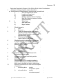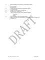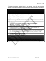
1
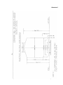
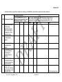
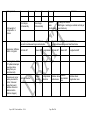
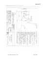
Technical Specification for High Output Tamping cum Stabilizing Machine capable
of 3500 sleepers per hour peak output for B.G. (1676mm).
(Specification No. TM/HM/HOT-STAB/Spc. 01, Rev. 01 of 2014)
1.0
General:
Due to increasing traffic on Indian Railways, the availability of time period
(Traffic Block) for working of track maintenance machines is reducing. There
is a need for high output machines with continuous operation so that even
smaller traffic blocks can be effectively utilized for maintenance of track.
Conventional tamping machines are used for levelling, tamping and lining
work of track. These maintenance operations result in reduction in lateral
stability of track thus rendering track unsuitable for high speeds immediately
after maintenance, particularly if the temperature are high. With the
increased quantum of traffic moving at high speeds, it is very essential to
restore the stability of track as early as possible. Controlled consolidation of
track by stabilization following the tamping would also lead to longer
retention of maintenance work. Presently, separate stabilizing machine is
used behind the tamping machines for the purpose. Need was felt to have a
machine which would combine both these activities and simultaneously
execute both the jobs in the same sequence. Some of the advantage
expected of having combined machine for the purpose instead of two
separate machine are:
a)
Operation of shunting is reduced and time lost in entry /exit to and from yard
to block section is reduced.
b)
A combined machine improves safety in movement vis-à-vis two machines
following each other.
c)
Track possession is utilized optimally.
d)
Reduces number of operating staff and also saves on fuel consumption thus
lowering operational cost.
This specification is laid down for a robust and sturdy high output track
lining, lifting , levelling and tamping cum stabilizing machine (hereinafter
called the machine), which should be suitable for track geometry correction
at maintenance and renewal/construction sites. The machine shall be
capable of improving the track geometry up to mainline high-speed
standards and continuous tamping and stabilizing operation for high and
durable output.
1.2
The technical specifications have been drafted to reflect the performance
and quality requirements of the machine in a neutral manner without bias to
any specific manufacturer. Bidders are requested to carefully study the
Spec of HOT with stabilizer – 2014
Page 1 of 30
specification and ensure that their machines fully comply therewith. If a
bidder feels that his machine can substantially meet the performance and
quality requirements but does not fully satisfy a particular system
specification, he should immediately seek clarification from the purchaser
prior to submission of bids as to whether such deviation is substantive or not.
The Bidder shall mention the deviations, if any, in the statement of deviation
from the specifications, giving the details how the functional requirements are
going to be met with.
1.3
The bidder shall specify the model offered and furnish a detailed technical
description of the same. Systems/sub-systems of the working mechanism of
the machine as per para 3.0 in particular and all the items of the
specifications in general shall be described in details in the “Technical
Description” along with sketches to show the manner in which the
requirements of the specifications are accomplished by the machine (model)
offered.
1.4
Photograph of the type of machine offered in work mode shall be enclosed
with the offer. These shall also show the close ups of various working
assemblies/systems. The tenderer shall furnish a compact disc or DVD or
USB showing the working of machine in real time under field conditions.
Tenderer shall also submit the names of countries & Railways where the
offered machines are working and their working can be seen if felt necessary
by the purchaser.
2.0
Dimensional and operating requirements:
2.1
The machine shall be diesel powered vehicle which shall be robust, of latest
design, reliable and suitable for working on plain track, transitions and curved
tracks (up to 100)on the Broad Gauge (1676 mm) of Indian Railways. The
design and dimensions of the machine and components shall be to metric
standards. Quality assurance during manufacturing shall be as per ISO9001.
2.2
The machine shall be self propelled bogie type vehicle.
2.3
The profile of the machine longitudinally and in cross section during transfer
as self propelled vehicle or towed in train formation shall be within the Indian
Railways schedule of Dimensions 1676mm Gauge (BG), revised 2004 with
the latest corrigendum and up to date correction slips issued. The minimum
and maximum moving dimensions are enclosed at Annexure-I. The tenderer
shall submit the sketches of machine in plan and shall give calculation for
moving dimension on 100 curves to show the extent of lateral shift at the
ends, centre and any other relevant cross sections. It shall be ensured that
the machine does not cause infringement while moving on a 10 0 curve.
Spec of HOT with stabilizer – 2014
Page 2 of 30
2.4
Adequate clearance shall be allowed so that no component infringes the
minimum clearance of 102 mm from rail level while travelling.
2.5
Axle load shall be lesser than 20.32t with minimum axle spacing of 1.83m.
Load per metre shall not exceed 7.67t.Axle loads upto 22.82t and lower axle
spacing may be permitted provided the load combinations do not cause
excessive stresses in the track and bridges of IR. Stresses in the track and
bridges shall be calculated by IR/RDSO, based on design data submitted by
the firm as per Annexure–II and decision of IR/RDSO shall be final in this
regards.
2.6
It shall have a minimum wheel diameter of 914mm (new wheel profile).
However, lesser diameter up to 730 mm (new wheel profile) can also be
considered, provided it meets the condition laid down in clause 2.4 at its
condemnation limit also rail wheel stresses for 72 UTS rails are
within
permissible limits. Forged wheels to Indian Railways profile shall be provided
on the machine. It is desirable that 50mm margin between new and permitted
worn wheel diameter should be available, but this should not be less than
20mm.The worn out wheel diameter (condemning worn out diameter) based
on the criteria of rail wheel contact stresses for various maximum axle loads
are as under:
Maximum axle load (tonne)
22.82
22.00
21.50
21.00
20.32
20.00
19.50
19.00
18.50
18.00
17.50
17.42
Minimum worn out wheel diameter
908mm
878mm
860mm
841mm
816mm
805mm
787mm
768mm
750mm
732mm
713mm
710.00
Permitted worn out wheel diameter should be specified by the manufacturer. The
diameter of wheel for assessment of permitted axle load will be the worn out
wheel diameter.
2.7
Permitted worn out wheel diameter should be specified by the manufacturer.
The diameter of wheel for assessment of permitted axle load will be the worn
out wheel diameter. The new wheel profile in the machine shall be as per
Indian Railway standard drawing attached as Annexure-III which is titled as
“WORN WHEEL PROFILE” wheel profile provided in Annexure-III.
Spec of HOT with stabilizer – 2014
Page 3 of 30
2.8
It shall be capable of negotiating curves up to 10 degree curvature (175m
radius), super elevation up to 185 mm and gradients up to 3% in travel mode.
The supplier shall specify the minimum attainable speed under the above
limiting conditions, which in any case shall not be less than 40 Kmph.
2.9
It shall be capable of continuous operation during the varying atmospheric
and climatic conditions occurring throughout the year in India. The range of
climatic conditions is as follows:
Ambient temperature
Altitude
:
:
Humidity
:
Maximum rail temperature :
0° to 55° C
Sea level to 1750m above
mean sea level
40 to 100%
70° C
2.10
During transfer from one station to another, it shall be capable of travelling
on its own at a speed of 80 kmph and at a speed of 100 kmph when hauled
in a train formation. Since the machine is likely to cover long distances on its
own power, the travel drive system should be robust to sustain these
requirements during the life of the machine. The machine should be capable
of hauling an 8-wheeler camping coach at a maximum speed of not less than
50kmph.
2.11
It shall be capable of working without requiring power block in electrified
sections. 25 KV AC power is used for traction through an overhead wire at
5.5 m above rail level. On bridges and in tunnels the height is restricted to
4.8m.
2.12
The machine or its any part shall not infringe the adjoining track as per
“Indian Railways Schedule of Dimensions 1676mm gauge (BG), Revised
2004 with the latest corrigendum and up to date correction slips issued” while
opening and closing the work. During working, also it shall not infringe the
adjoining track and it shall be possible to permit trains at full speed on that
track. Minimum spacing of track is 4.265 m centre to centre.
2.13
It shall be possible to drive the machine in both directions at the
same speed. Driving cabin for the purpose should at both end of the
machine.
3.0
Working Mechanism
3.1
The machine shall consist of a tamping portion and stabilization unit. The
stabilizing unit can be in the form of trailer linked with the tamping portion of
machine by suitable coupling. The stabilizing unit shall be operated by same
operator who is operating the tamping unit. No separate operator for
stabilizing unit shall be required. Stabilizing unit shall be so synchronized
with the tamping unit that stabilization can be made to automatically start
from the first sleeper tamped and stop at the last sleeper tamped. The
Spec of HOT with stabilizer – 2014
Page 4 of 30
machine should be capable of performing both function of tamping and
stabilizing independently also. At the parameters specified against clause 3.6
for achieving durable compaction, the machine shall be capable of carrying
out automatic lifting, levelling, tamping, lining along with simultaneous
stabilization of the tamped track, at the peak rate of 3500 sleepers or more
per hour over a period of not less than 10 minutes and an average of not less
than 2700 sleepers in an effective hour of working on all type of track
structures in Indian Railways with uniform sleeper density which may vary
from 55 to 75cm. The time shall be counted from start to finish of tamping
work at work place. Stoppage of work not attributable to machine shall be
discounted. The setting up time and winding uptime shall be measured and
the total time taken by the two operations of setting up and winding up of the
machine together shall not exceed 10 minutes. The setting up time shall be
counted from the time machine arrives at site to the time work is started. The
winding up time will be counted from the time the work is stopped to the time
machines starts moving away from the work site. The tenderer shall furnish
the full details of the working cycle of the machine, its timings and other
operational details.
3.2
The machine shall be provided with automatic tamping equipment. Separate
tamping units have to be provided for each rail. Each unit comprising of
tamping tools, shall be operated hydraulically.
3.3
The necessary work units may shall be positioned on an under-frame
separate from the main frame capable of cyclic movement from sleeper to
sleeper, independent of the main frame, to facilitate continuous working for
high output so that the operator does not get undue fatigue due to
acceleration pull, braking jolt in each tamping cycle.
3.4
The tamping below the sleepers, after the track geometry correction, shall be
based on vibratory squeeze principle to achieve a durable compaction.
3.5
The ballast depth ranging from 300 mm to 350 mm shall be effectively
compacted having zone of influence of tamping of approx. 150mm layer
below the bottom of sleepers. The maximum depth of concrete sleeper is
equal to 210mm. There should be provision for step-less adjustment of the
depth of tamping tools to suit different types of sleepers.
Amplitude of vibration, vibration pressure, vibration frequency, squeezing
pressure, squeezing time and tamping depth of the tamping tools in tamping
unit and vibration frequency, vertical load of stabilizing unit should be such
that durable compaction under the sleeper is achieved. The vibration
frequency and vertical load of stabilizing unit should be such that controlled
settlement, lasting consolidation and substantial increase in post tamping
lateral ballast resistance of sleeper is achieved.These parameters to achieve
a durable compaction shall be specified by the tenderer. Details of all the
above parameters will be submitted in the offer.
The machine should be capable of giving the output as stipulated in Clause
3.1 with the following tamping parameters:
3.6
Spec of HOT with stabilizer – 2014
Page 5 of 30
a. Squeezing time of 0.6 sec. or more
b. Squeezing pressure of 120 kg/cm2 or more
c. Tamping depth - upper edge of tool blade should be 10 – 12mm
below the bottom of the sleeper.
3.7
The tamping tools should come to rest automatically after they encounter the
resistance from the ballast to pre-selected squeezing pressure and hold the
squeezing pressure for pre- set time. It shall be possible to vary the
squeezing pressure, squeezing time, to suit varying track structure and
ballast conditions.
3.8
The lifting system shall be such that the track can be lifted without bearing on
the ballast. The machine frame and the lifting system shall be strong enough
to bear the track lifting forces for all types of track structures for 150 mm lifts
in one go. The free rail length between the two bogies of the main machine
shall be long enough to permit the track lifting up to 150 mm in one go,
having 60 Kg rails on concrete sleepers without excessive stresses in the rail
or on the lifting mechanism. The lifting system should hold the rail
continuously rather than releasing and re-lifting the rail at every tamping
cycle. However, the lifting/lining system and actual tamping should be so
synchronized that the track is stiffly held in position and there is no
movement in the track when the tamping tool is inserted for tamping. This is
required to ensure that the lift and slew are not altered during the process
while track is being tamped
3.9
The machine shall be provided with automatic levelling equipment which will
permit correct levelling of the track including provision of super elevation
along with tamping. Tolerance achievable shall be as follows:
Unevenness
Cross level
Alignment
Twist
:
:
:
:
+ 1 mm on 3.6 m Chord
+ 1 mm
+ 2 mm on 7.2m Chord
1 mm/m
3.10
The machine shall be fitted with automatic lining equipment capable of
carrying out lining simultaneously with levelling. The machine shall also have
the ability to slew 60 Kg concrete sleeper track up to 150 mm in one go for all
type of track structures.
3.11
The machine shall be capable of tamping, lifting, lining and stabilization of
track with up to 60 Kg long welded rails or short welded rails or fish-plated
rails laid on pre-stressed concrete sleepers, steel trough sleepers, CST-9
and wooden sleepers. The normal sleeper spacing in different track
structures on Indian Railways is 55 cm to 75 cm.
3.12
The working cabins of the machine shall be air-conditioned. The airconditioning provided shall be of robust industrial design capable of
operating in highly dust laden environment. However the electronic
Spec of HOT with stabilizer – 2014
Page 6 of 30
equipments should be so designed that the machine shall be able to work
without air-conditioning under the climatic conditions described in para
no.2.9.
3.13
The tenderer may be required to show working of his machine under field
conditions, The tenderer shall indicate the name of the Railway system
where the types of machines offered are working.
3.14
It shall be possible to control the target track geometry parameters, in
infinitely variable steps from operators/front cabin. To suit this, suitable
proportional /servo control systems shall be provided.
3.15
On Indian Railways, rail top to sleeper bottom depth may vary from 260mm
to 420mm.
3.16
The machine shall be provided with a computerized unit for the overall
control of its working system for all possible track geometry. The system shall
be so designed that for working on tracks with pre-decided target geometry,
the standard track geometry data as well as correction values can be entered
prior to work either directly on system or via USB, CD or DVD. For working
on tracks with unknown target geometry, it shall be possible to determine the
correction values by making a measuring run and subsequent geometry
compensation of the recorded data considering obligatory point and
constrains of lifting and lining etc. Interactive processing of the target profile
by the operator shall be possible. Track parameters shall be displayed in
graphic as well as text form on a colour monitor. It shall be possible to guide
the working system of the machine continuously and automatically by this
unit. The software shall be Windows based. The hardware shall be sturdy for
operations under conditions of shock, vibrations, dust, electromagnetic
influences from outside and interruption of power supply. The unit shall have
adequate memory to keep records of minimum 100 km of work performed,
new track geometry obtained and enables transfer of the data via USB, CD
or DVD as required.
3.17
In addition to the computer system provided on the machine for its own
controls, the machine shall be provided with an industrial quality heavy duty
portable computer (Laptop-tough book) for keeping record of overall aspects
of working, spares management and reporting. The detailed specifications of
the laptop are enclosed as annexure-IV.
3.18
The machine shall be capable of measuring and recording the unevenness,
alignment and cross level in real time on a print out before and after the
tamping and stabilization by the machine. It shall also record progress vis-avis time.
3.19
The stabilizing unit shall be an integral part of the machine. It shall achieve
effective and continuous stabilization of the track and shall be able to match
the working speed of the tamping portion without loss in stabilizing quality.
Spec of HOT with stabilizer – 2014
Page 7 of 30
3.20
During the operation, the stabilizer unit shall be capable of lowering the track
in a controlled manner, while maintaining the pre-stabilized geometry. Proper
longitudinal and cross-level control mechanisms shall be provided to achieve
this. The manufacturer shall clearly explain the mechanism in its offer.
3.21
The stabilizing unit shall be capable of continuous stabilization of track
including typical Indian Railway heavy concrete sleeper track. To achieve a
controlled settlement and a lasting consolidation of such heavy track, it shall
be equipped with minimum two independent stabilizing units, applying
suitable and variable vertical load upto12 tonnes or more each.
3.22
The stabilizing unit shall be capable of pre loading the track. While pre
loading the track by stabilizing unit, the driving wheels should provide
adequate adhesion to avoid wheel slippage/loss of traction and risk of
derailment.
3.23
The horizontal and vertical force and frequency of vibration shall be
adjustable so as to carry out effective stabilization on various types of track
structures.
3.24
The machine shall be equipped with suitable mechanism to control the
degree of settlement of the track which shall copy the pre-stabilizing
geometry by automatically increasing/relieving the vertical load on the
stabilizing units. For optimum results, mechanism shall work independently
for the left and right hand rail.
3.25
It shall be possible to steplessely pre-select the frequency of stabilizer
vibrations which shall be between 0-45 Hz for optimum adjustment to suite
the various kinds track structure. During work near fixed structures like
bridges, it shall be possible to pre-select a frequency within that range which
is beyond the natural frequency of the structure. In this context, it is also
essential that the vibrations be automatically cut off, when the machine
working speed reduces below prescribed cut off speed to be prescribed by
the manufacturer in the offer.
3.26
The stabilizing unit shall be equipped with a frequency modulation measuring
unit for optimum regulation of frequency. The machine shall be equipped with
display units for monitoring vibration frequency, and degree of settlement on
both rails.
3.27
To avoid damages on the rail surface by excess friction and force by the
rollers and to achieve a force free resettlement of the ballast grains only
lateral vibrations shall be permitted and those lateral vibrations by stabilizing
unit shall be created without any vertical impact on ballast..
3.28
The tamping tool holding arrangement in tamping arm of tamping bank
should be cylindrical compressible type with bolting and dowel arrangement
Spec of HOT with stabilizer – 2014
Page 8 of 30
such that no hammering is normally required for fixing and removing the
tamping tools.
3.29
The machine shall be warranted for 1200 working hours or 500000 tamping
insertions with stabilization or 18 months from the date of commissioning and
proving test of equipment or 24 months after delivery at ultimate destination
in India which ever shall be earlier. Working hours for this purpose will be
traffic block time during which machine is deployed for tamping work.
4.0
Diesel Engine:
4.1
The machine shall be powered by diesel engines preferably indigenous with
proven record of service in tropical countries with wide service network in
India. Robust construction and low maintenance cost are of particular
importance. Adequate allowance shall be made for de-rating of diesel engine
under the most adverse climatic conditions mentioned in the specification
elsewhere. High speed diesel oil to Indian standard specification shall
normally be used. A minimum fuel tank capacity sufficient for continuous
operation for 8 hrs will be desirable. Sight glass type fuel measuring gauge
shall be provided on the fuel tank. For starting the engine, storage batteries
of well known indigenous make with wide service network in India shall be
provided. The engine shall normally be push button start type.
4.2
The supplier should furnish the information regarding make and model of the
engine proposed to be used and details of agency which will provide after
sales service support and availability of spares in India.
4.3
Since the engine is to work outdoor under extreme dusty conditions, the air
intake system shall be designed suitably so as not to allow dust through air
intake system.
4.4
There is a likelihood of dust deposition over the engine body and surrounding
area over the lubricants spills over. These should be easy to access for daily
cleaning and routine maintenance. In case, air cooled engines are proposed
by the supplier, maintenance equipment for cleaning and maintenance of the
air cooling fins shall be provided by the supplier along with the machine.
4.5
The engine parameter monitoring gauges like temperature, rpm, and lube oil
pressure shall be direct reading type mounted on the engine backed up by
electrical/mechanical gauges in the operator’s cabin showing the absolute
readings along with safe limits suitably coloured. There shall be audiovisual
warning (safety mechanism) to the operators in case of any of these
parameters exceeding the safe limit and engine shut down circuit in case of
operator’s failure to respond.
4.6
Suitable and rugged mechanism should be provided to start the prime mover
at no load and gradual loading after the start of the prime mover.
Spec of HOT with stabilizer – 2014
Page 9 of 30
4.7
The engine power take off shall be coupled to the main gearbox through a
flexible coupling / cardon shaft (propeller shaft). The engine shall be mounted
on suitable Anti-Vibration Mountings.
5.0
Drive Mechanism:
5.1
The machine should be provided with an efficient traction drive system for
traction during the operation.
5.2
The machine’s driving system shall be through hydro dynamically coupled
power/transmission arrangement capable of achieving full speeds in travel
mode in both the directions. However, the system should be so designed that
all the driving wheels work in synchronization and there is no
slippage/skidding of the wheels during the work drive.
5.3
The driving mechanism, in working mode, shall be adequately designed to
handle the acceleration and braking forces at each tamping cycle. A suitable
synchronization circuit to control the synchronization of lifting/lining/tamping
process with the machine drive/braking system in working mode shall be
provided to prevent any damage to the machine systems on account of nonsynchronisation.
5.4
Suitable differential systems may be provided between coupled wheels on
the same bogie.
5.5
Suitable flow divider/throttling arrangement may be provided to equalize the
tractive effort amongst different bogies. Adequate gauges shall be provided
to indicate the power sharing among different driving bogies to prevent
overstressing of any traction bogie or its components.
5.6
The tenderer shall provide the necessary technical details including circuit
diagrams to confirm the above requirements.
5.7
Adequate gauges and solenoid valves shall be provided near linkage
assembly for indication, flow control and carrying out necessary adjustment
in the field.
5.8
To the extent possible hydraulic and pneumatic component/assembly should
be fixed at suitable location preferably on the side frame of the machine so
as to avoid the need of going on top of the machine for day-today
maintenance schedules.
5.9
The pneumatic circuit should be provided with air dryer for the smooth
working of pneumatic components.
6.0
Cooling System:
Spec of HOT with stabilizer – 2014
Page 10 of 30
6.1
The cooling system shall be efficient and designed for a maximum ambient
temperature of 55°C. Supplier shall note that the machine shall be working
under extreme dusty conditions and the cooling mechanism shall be
maintainable under these conditions.
6.2
Adequate heat transfer arrangement for the hydraulic system shall be
designed and provided so that under extreme heat conditions as mentioned
in Para 2.9 above, the system oil temperature does not go beyond 85°C.
7.0
Brakes:
7.1
The machine shall be fitted with compressed airbrake system applying
brakes equally on all wheels and provision shall be made to connect air
brake system of the machine to that of camping coach when the machine is
hauling it. The brakes shall be protected from ingress of water, grease, oil or
other substances, which may have an adverse effect on them. The brake
lining shall be suitable for high ambient temperature of 55°C. The force
required for operating the brake shall not exceed 10 Kg. at the handle while
applying by hand and 15 Kgs. on the pedal, when applied by foot.
7.2
Machine shall be equipped with suitable arrangement of braking so that while
attached in train formation, machine can be braked by traction vehicle having
compressed air braking system.
7.3
There should be provision of emergency brake application in the machine
either travelling alone or coupled with the camp coach, in addition to the
normal braking system of the machine, using the compressed air. The
emergency braking distance (EBD) of the machine on the Indian railway
track at the maximum designed speed on a level track shall not be more than
600m. Design calculations for the braking effort and EBD at the maximum
design speed of the machine on level track & at falling grade of 1 in 33
should be provided by the supplier. Brake design details are to be submitted
as per annexure V.
7.4
Mechanical brakes shall also be provided in addition for use as parking
brakes.
7.5
Clearly visible brake lights shall be provided at both the ends of the machine,
which will be automatically operated when brake is applied and switched off
when brake is released. This will be to alert the operator of machine following
this machine when the machines are working in groups.
8.0
Horn, Hooters and safety switches:
8.1
The machine shall be provided with electric/pneumatic horns facing outwards
at each end of the machine at suitable locations for use during travelling and
to warn the workmen of any impending danger at the work spot. The horns
shall be distinctly audible from a distance of at-least 400 m from the machine.
Spec of HOT with stabilizer – 2014
Page 11 of 30
These horns shall be operated by means of push buttons provided in the
cabins.
8.2
Adequate numbers of safety stop switches should be provided all around so
that in case of any danger to worker during working, the working can be
stopped immediately.
8.3
Safety equipments like jacks, pullers and other such equipments specific to
the machine for restoring failed units of the machine during working shall be
provided on the machine.
8.4
Machine shall be provided with emergency backup system to wind up the
machine quickly in the event of failure of prime mover or power transmission
system of the machine.
8.5
Pneumatically operated hooters shall be provided facing outwards at each
end of the machine at suitable locations, operated by means of push buttons
provided in the cabins to warn the staff working on/around the machine about
approaching train on adjoining track.
9.0
9.1
10.0
Hooks and buffers:
The machine shall be fitted with hooks and buffers of IRS design on both
ends for coupling it with camping coach or other vehicles and running in train
formation and for attachment with the camping coach.
Suspension system:
10.1
The suspension system shall be preferably of two-stage type with suitable
spring and damping arrangement. Spring for primary and secondary
suspension shall be designed to cater for actual service conditions. Effective
measure shall be adopted to minimize the weight transfer while starting,
stopping and during runs.
11.0
Electric equipment and lighting:
The electrical equipment to be provided shall conform to relevant standard
specifications and shall be suitable for Indian climatic conditions. The
machine shall be equipped with latest twin beam headlight assembly
conforming to RDSO specification No. ELRS/SPEC/PR/0024 revision-1
September, 2004 with the amendments ensuring a light intensity of 3.2 lux at
ground level at track centre at a distance of 305 metres away on a clear dark
night), at each end and with two front and rear parking lights, which can be
switched to red or white according to the direction of the travel. Powerful
swivelling flood light shall also be provided to illuminate the working area
sufficiently bright for efficient working during night. The amber colour flasher
Spec of HOT with stabilizer – 2014
Page 12 of 30
lights shall be provided on the both ends of the machine to give indication to
the train arriving on other line about any impending danger.
12.0 Chassis and under-frame:
The chassis shall be fabricated from standard welded steel sections and of
steel sheets, so as to permit transportation of the machine in train formation
without endangering safety of the train.
The under-frame shall be
constructed with rolled steel section and/or plates and shall be designed to
withstand a horizontal squeeze load of 102t at buffers i.e. 51t at each buffing
point. The under frame shall be sufficiently robust for safe travel of the
machine in train formation and not necessarily as the last vehicle.
13.0 Cabins:
13.1
The machine shall be equipped with fully enclosed air conditioned and
pressurized cabins with safety glass window at both ends. In view of the high
ambient temperature prevailing in India, special attention should be paid to
free circulation of air and ventilation in the driver’s cabin. It shall be possible
to have a clear view of the track ahead while driving the machine in both the
directions from the cabins at either end. The cabin layout shall be such that,
before leaving the machine, the operating staff has full view on both the
sides, to avoid any danger to them from trains on the adjacent tracks.
Additional driver’s cabin shall be provided if the view while driving is not clear
for safe travel in both directions.
13.2
The gauges, warning panel and controls shall be suitably located in the
operator’s cab so that they can be observed without undue fatigue to the
operator. Screen wipers preferably operated by compressed air or electrically
operated shall be provided on the wind screen.
13.3
Suitable number of fire extinguisher (dry chemical type) shall be provided in
all the cabins.
13.4
The machine shall be provided with well designed space for keeping the
tools and spares required for onsite repairs of the machine to attend the
breakdowns and other working requirements.
13.5
The operator’s cabin shall be ergonomically designed to have easy access to
all the controls. The operator shall have a full view of the working area from
the operating seat to have full control over the work. The stabilizing unit shall
also be controlled from the main machine.
14.0 Tools and Instruction Manuals:
14.1
Each machine shall be supplied with a complete kit of tools required by the
operator in emergency and for normal working of the machine. The tenderer
shall along with his offer submit the list of tools to be supplied along with
Spec of HOT with stabilizer – 2014
Page 13 of 30
each machine. The list of tools to be provided shall include all tools
necessary for maintenance and repair of the entire machine including
specialized equipment. All special tools shall be listed and catalogued
illustrating the method of application. The list can be modified to suit the
purchaser’s requirement, while examining the offer.
14.2 Detailed operating, maintenance and service manual shall be specifically
prepared in English language and four copies of each of the same shall be
supplied with each machine.
14.3 The supplier shall also supply circuit diagrams of electrical, hydraulic,
pneumatic and electronic circuits used on the machine. Trouble shooting
diagram/table shall also be supplied. In addition, the supplier shall provide
dimension drawings with material description of items like rubber seals,
washers, springs, bushes, metallic pins etc. Main features such as type, rpm
& discharge etc of items like hydraulic pumps, motors and such other bought
out components/assemblies shall be furnished by the tenderer. These shall
be specially prepared in English language and four copies of these shall be
supplied with each machine.
14.4 While offering the machine for first inspection, the supplier shall submit one
copy of complete technical literature in English language including operation,
service and field maintenance manual/instructions and complete electrical,
hydraulic & pneumatic circuit diagrams, trouble shooting charts, component
drawings/ description and other relevant technical details as a reference
documents for the inspecting officer.
14.5
One portable diesel operated D.C. welding generator of reputed make
(preferably made in India) with a minimum 5 KVA capacity along with
sufficient length of cable or lead shall be provided with the machine for day to
day repairing of machine and its wearing parts.
14.6
The firm shall provide detailed technical drawings and specifications of
wheels and axles used in the machine. The above details shall be provided
in four sets with each machine.
14.7
One set of all the manuals and diagrams should also be sent to the
Principal/IRTMTC, Allahabad, one set to ED/TMM, RDSO, Lucknow, one set
to DTK (MC)/Railway Board and one set to Director/IRICEN/Pune along with
supply of first machine of similar group. In case, there is any subsequent
amendment in above documents based on field performance, the
amendment/amended documents should also be sent to above mentioned
authorities.
15.0
Spare parts:
Spec of HOT with stabilizer – 2014
Page 14 of 30
15.1
The tenderer should quote, apart from main equipment, separately for the
mandatory spares as well as for recommended spares required for two years
of operation along with description, part number, quantity, cost, whether
imported or indigenous. The expected life of components shall be advised
along with their condemning limits. The supplier shall be responsible for the
subsequent availability of spare parts to ensure trouble free service for the
life of the machine (15 years).
15.2
For indigenous parts and brought out components and assemblies, the
relevant technical details shall be supplied while offering the first machine for
inspection.
16.0
Maker’s test certificates:
16.1
Copies of marker’s certificate guaranteeing the performance of the machines
should be supplied in duplicate along with the delivery of each machine.
17.0
Operators:
17.1
The number of operators and allied staff for working of the machine under
normal working condition may be indicated, specifying their duties and
minimum qualifications.
18.0
Service Engineers:
18.1
The contractor shall provide at his own expense the services of competent
engineers during the warrantee period for warrantee related issues. The
service engineers shall be available for the commissioning of the machine for
regular service, and for training to the operating, repairing and maintenance
staff of the machine. The engineers shall also advise the Railways on
appropriate maintenance, testing, operating, repair and staff training facilities
that are necessary for the efficient performance of the machines.
18.2
During the warrantee period of the machine the supplier must ensure trouble
free availability of the machine in good working condition for at least 90 % of
the time and accordingly they must ensure availability of spares &services of
competent service engineers at prompt disposal of user railways.
19.0
Optional equipment :
19.1
Tenderer is expected to quote for optional equipment separately for each
item giving the advantages/functions of such optional equipment. Tenderer
shall also indicate whether such equipments are already in use on machines
elsewhere indicating the user Railway system.
Spec of HOT with stabilizer – 2014
Page 15 of 30
20.0
Inspection of the Machine:
20.1
While inspecting the machine before dispatch from the supplier’s premises,
the inspecting officer shall verify the conformity of the machine with respect
to individual specification as above. The machine’s conformity /non
conformity with respect to each item shall be jointly recorded before issue of
the inspection certificate and approval for dispatch of the machine as per
Annexure–VI enclosed.
21.0
Guarantee:
In addition to the special conditions of contract dealing with warranty, the
following will apply.
Should any design modification be made in any part of the equipment
offered, the period of 24 months would commence from the date of the
modified part is commissioned in service for the purpose of that part and
those parts which may get damaged due to defects in the new replaced part.
The cost of such modification should be borne by the supplier.
22.0
Issue of Provisional Speed Certificate:
Whenever a new rolling stock is introduced in Indian Railways, a provisional
speed certificate is issued by RDSO based on certain design parameters of
the vehicle. Final speed clearance of the vehicle is given after conducting
detailed oscillation trials of the vehicle, which is a time taking process.
Therefore, issue of provisional speed certificate for the vehicle becomes a
necessity and based on the same the approval of running of the vehicle on
Indian Railway track is taken from Commissioner of Railway Safety. For
issue of provisional speed certificate, following actions are required to be
taken by the suppliers.
a)
Current supplier , whose models are approved :
The supplier shall give details of the model, year of introduction in Indian
railway, details of speed certificate issued etc. The supplier shall certify that
no change has taken place in the model being offered with respect to design
of under change i.e. suspension system/ arrangement, wheel & axle
assembly, bogie braking arrangement loading pattern of the vehicle etc and
the distribution of axle loads, lateral forces, unstrung mass and braking force
coming on rail is the same if, there is any change in above respect, the action
shall be taken as detailed in Para (b) below.
b)
Current Supplier, whose models are not approved / or new :
As soon as the supplier completes the design of the machine as per
specification, the technical details as per Annexure (VII and VIII) shall be
Spec of HOT with stabilizer – 2014
Page 16 of 30
supplied for processing of provisional speed certificate for the machine so
that it can be permitted to move on track on case to case basis, more
technical details (other than mentioned in Annexure VII and VIII) can also be
asked for issue of provisional speed certificate for the machine. The firm will
also submit the technical details as per performa placed at Annexure-II for
NUCARS vehicle dynamic simulation.
c)
New supplier, whose models are new:
The technical details shall be supplied as detailed in para (b) above.
23.0
Acceptance Test:
23.1
In addition to verification of the various items of specifications covered earlier
the purchaser’s nominee shall carry out the following tests in India at the
purchaser’s premises at the time of commissioning of the machine. The precommissioning tests shall be completed and the machine shall be
commissioned within 90 days of its arrival at the premises of the final
consignee.
23.2
The Dimensional check of loading gauge, i.e. maximum moving dimensions,
buffer heights, clearances, length of machine bogie distance etc.
Testing for negotiability 10° curve and1 in 8½ turnouts.
23.3
23.4
Running speed tests on the Indian Railway main line track on the first
machine in accordance with procedure outlined in annexure- IX with the
machine running upto speed 10% higher than the maximum speed
mentioned in Para 2.10 above.
23.5
Construction and engineering of the machine and its ability to perform all the
functions as laid down in the specifications above.
23.6
Actual output and performance test to be conducted on the first machine.
These tests shall be conducted under field conditions on Indian Railway. An
electrified section shall be chosen for this test.
The general conditions of tests and test parameters shall be as follows:
a. Machine crew shall be either trained personnel of Indian Railways or
the staff of the supplier.
b. Dry weather, ambient temperature between +0°C to + 55°C.
c. Plain Track or curve of radius not less than 1000 m.
d. Gradients up to 1/200.
e. Rails and sleepers in good conditions and properly fastened.
f. Concrete/wooden/steel sleepers.
g. Clean ballast cushion of minimum 100 mm in sufficient quantity below
the bottom of the sleepers and generally not cemented.
h. LWR track.
Spec of HOT with stabilizer – 2014
Page 17 of 30
i. Regular sleeper spacing of 60/65 cm with a tolerance of + 3 cm on
straight track.
j. Formation good.
k. General lift during working up to 20mm.
l. Maximum slew during working up to +10 mm.
m. Amount of lowering up to 20 mm by stabilizing unit maintaining track
parameters within permissible range.
n. Lifting of track in non- working mode of 150 mm in one go. to be
conducted at manufacturer’s premise/siding.
o. Slewing of track in non-working mode of 150 mm in one go. to be
conducted at manufacturer’s premise/siding.
p. At the parameters specified against clause 3.6 for achieving durable
compaction by tamping unit and controlled settlement, lasting
consolidation and desired increase in lateral ballast resistance of
sleeper by stabilizing unit, the machine shall be able to tamp and
stabilize 2700 sleepers in one effective hour of working. The time shall
be counted from start to finish of tamping work at work place. The
machine shall also be able to achieve a peak tamping and stabilizing
rate of 3500 sleepers or more per hour over a 10 minutes period at the
above prescribed parameters. Stoppage of work not attributable to
machine shall be discounted. The setting uptime and winding uptime
shall be measured and the total time taken by the two operations of
setting up and winding up of the Machine together shall not exceed 10
minutes. The setting up time shall be counted from the time machine
arrives at site to the time work is started. The winding up time will be
counted from the time the work is stopped to the time machines starts
moving away from the work site.
24.0 Should any modification be found necessary as a result of the
shall be carried out by the supplier at his own expenses.
****************
Spec of HOT with stabilizer – 2014
tests, these
Page 18 of 30
Annexure-I
Spec of HOT with stabilizer – 2014
Page 19 of 30
Annexure II
Machine details required for simulation of machine on NUCARS or similar Track-vehicle simulation software
Parameters required
C.G. of component in x, y, z
Mass in Kg and Mass moment of inertias in Kg- m^2 of
SL. NO.Component’s Name direction from rail level in mm
component in three dimension space about their C.G
(Referenced point 1st axle)
X
Y
Z
Mass
Ixx
Iyy
Izz
Super structure with
vehicle frame
(machine structure
1.
kept on secondary
suspension of front
and rear bogie)
Front Bogie frame
including brake
2.
rigging
3.
4.
5.
6.
Rear Bogie frame
including brake
rigging
Transmission system
device (hydraulic.
Mechanical or
electrical traction
motors)
Wheel axle set
including axle boxes
which constitute the
unsprung mass
Mass of Items
included in unsprung
mass partially or fully
along with their
Spec of HOT with stabilizer – 2014
Total unsprung mass
Page 20 of 30
name per axle
7.
Total weight of
components in
tonnes
1
2
Front bogie
full assembly
3
4
5
Rear bogie
full assembly
Primary suspension element stiffness
per axle box between bogie and axle box
8.
Suspension stiffness
details in Kg/mm
9.
Damping force details
( If hydraulic damper
used give there
rating force per
meter/second)
10.
Clearance in mm or
radian provided for
motion between
bogie frame and
machine frame for
relative motion
(motion stopper)
6
Machine
frame
full structure
in tonnes
Full weight of vehicle
(front bogie + rear bogie +vehicle car body or
super structure)
Secondary suspension element stiffness
per side between bogie and machine frame
Vertical stiff
Lateral stiff Longitudinal stiff
Vertical stiff
Vertical direction
Lateral
direction
Spec of HOT with stabilizer – 2014
Lateral stiff
Rotation
Longitudinal Rotation about
about lateral
direction
vertical axis
axis
Page 21 of 30
Longitudinal stiff
Rotation about
longitudinal axis
11.
Detail of location of suspension springs and
Dimension of location of
dampers and shock absorbers with support
suspension elements
drawing
12.
Details of centre pivot
arrangement working and
Provide detail arrangement drawing and description
location
13.
Set of drawings and
design description
Detail of location of suspension springs and dampers
and shock absorbers with support drawing
Concerning with general arrangement of vehicle, bogie general arrangement, suspension arrangement
details, suspension clearances drawing, detail written description of configuration and loading pattern
accompanies design particular of vehicle bogie.
Spec of HOT with stabilizer – 2014
Page 22 of 30
Annexure-III
Spec of HOT with stabilizer – 2014
Page 23 of 30
Annexure-IV
Specifications of Heavy duty Industrial Quality Water proof & shock proof
Laptop (Tough book)
CPU
Intel Core i-5 processor ,speed 2.4 GHz or higher
version
Operating System
Windows 7 professional or higher version
RAM
2 GB or more and expandable upto 8GB
Storage
Shock mounted flex connect hard drive with quick
release 500 GB or More
Display
Minimum 13” high definition LED or better with anti
reflective and anti glare treatment
Keyboard
Backlit 61 key QWERTY keyboard. Touchpad with
virtical scrolling support.
Wireless
Integrated Gobi 2000 mobile broadband or better,
Bluetooth V 4.0 or better.
Durability features
Product shall be durable and meet the latest MIL
standard.
Moisture and dust resistant screen, Key board and
touch pad.
Pre Loaded Softwares
Antivirus software for 18 months validity
Microsoft office 2007 complete bundle
Power supply
Long life Li-ion battery, minimum 5400 m AH
Warranty
3-year warranty
Spec of HOT with stabilizer – 2014
Page 24 of 30
Annexure-V
BRAKE DESIGN DETAILS OF THE MACHINE FOR
CALCULATION OF EMERGENCY BRAKING DISTANCE
Tare & gross weight of the machine in Kilograms
Brake power in Kilograms
Type of Brake blocks
Brake block area in Square Centimetres
Brake Rigging Diagram
Type of Brake system
Spec of HOT with stabilizer – 2014
Page 25 of 30
ANNEXURE-VI
INSPECTION CERTIFICATE CERTIFICATE OF INSPECTION OF TRACK MACHINE
(
) BY INSPECTING OFFICIAL AND APPROVAL FOR DESPATCH OF
MACHINES
(STRIKE OUT WHICHEVER NOT APPLICABLE)
This
is
to
certify
that
I
have
inspected
the
machine
(type)_______________________________bearing Sl.No._________________ from (date)
____________to _____________at (Place) ________________ for its conformity/nonconformity with respect to the laid down Technical Specifications in contract Agreement
No.________________________________
dated_______________________between
President of India through Director Track (Machines) and M/s. (Name of Supplier)
___________________________ _____________________________________.
The detailed Inspection Note regarding its conformity/non-conformity to the laid specifications
is enclosed along with as Annexure’A’. It is observed that (strike out whichever is not
applicable):The Machine conforms to all the laid down specifications.
The machine conforms to all the laid down specifications except those at
Sl.No.________________________.
The above deviations are minor/major affecting/not affecting the performance of the
equipment in substantial way.
The following T and P/manuals/drawings are to be supplied alongwith the machine:
__________________________
__________________________
_________________________
Based on the above, the Machine is certified/not certified to be conforming to the
specifications.
The machine is approved/not approved
________________(Consignee) Indian Railway.
for
despatch
to
_____________
SIGNATURE AND DATE
For M/s.__________________
_________________________
INSPECTING OFFICIAL
(NAME AND DESIGNATION)
for and on Behalf of President of india
Spec of HOT with stabilizer – 2014
Page 26 of 30
Annexure : VII
1.
2.
3.
4.
5.
6.
7.
8.
9.
10.
Particulars Required in Respect of the Rolling Stock Under Consideration
A diagram showing elevation salient dimensions :
a) Wheel spacing, Wheel diameter, bogie centres, and axle load.
i)
Over all length of the vehicle
:
ii)
Length over head stock
:
iii)
Length over buffers
:
iv)
Distance apart for Centre of buffers
:
v)
Max./Min. height of centers of buffers
(above rail level)
b)
i)
Wheel base
ii)
Axle load (max)
iii)
Bogie Centres
:
Wheel dimension
:
i)
New
:
ii)
Worn out
:
i)
Tread and flange profile of the wheel
:
indicating clearly whether it is Indian
Railway standard profile or differs from
standard flange profile.
ii)
Wheel gauge dimension –
:
(back to back of tyre flange).
Whether the stock is designed to be used as :
a general purpose or in a closed circuit in
specified sections under defined conditions.
Maximum design speed
i)
Own Power
:
ii)
In train formation
:
Unsprung weight per axle in tonnes
i)
Driving axle
:
ii)
Running axle
:
Expected lateral force in tonnes per axle
:
At maximum design speed.
Increase in the impact load during motion
(Dynamic Augment)
Method of operation :
Whether single only or coupling together is
possible. If coupling is possible, the number
which can be coupled and what is trailing load.
Maximum tractive effort at start and at the speed
of operation i)
at working drive
at start
at operation speed
ii)
at transfer drive
at start
at maximum speed
Spec of HOT with stabilizer – 2014
:
:
:
:
Page 27 of 30
11.
12.
13.
14.
15.
16.
Maximumbraking force coming on to the rails per wheel
at working axle
:
at transfer axle
:
Drawing indicating suspension arrangement details
of bogie and axle.
Height of centre of gravity from rail level
Height of floor from rail level
Type of coupler provided -Indian Railways Standard
Coupling
:
Buffer
:
Any infringement to the moving dimensions
Sketch provided in the Indian Railways Standard Schedule of Dimensions –
Chapter IV (A).
Spec of HOT with stabilizer – 2014
Page 28 of 30
Annexure : VIII
Following information as detailed below is also required along with the information
required for processing the case for issue of provisional speed certificate for new vehicles
S.No.
1. a)
b)
2.
3.
4.
5.
6.
7.
8.
9.
10.
11.
12.
13.
14.
Item
Brake System details
Gross Braking Ratio
Brake rigging arrangement drawing and calculation of braking force
Maximum Braking Effort. at start and at the speed of operation a) at working drive
at start
:
at operation speed
:
b)
at transfer drive
at start
at maximum speed
:
Characteristics of springs used in suspension indicating free height, working height,
dynamic range, stiffness and locations etc.
Characteristics of the dampers if used, and over all damping factors and locations
of dampers.
Calculation of the following frequency of the vehicle to be attached :Bouncing
ii) Pitching iii) Rolling
Wave length of free axle and bogie
Write up and salient design calculation on suspension system, type of
suspension- whether it is of coil suspension with or without dampers and
laminated bearing springs and double link suspension.
What are lateral clearance of axle box / horn, wheel flange/rail and other locations
for the negotiability of the vehicle on curve and turn out (enclose Vogels Diagram
for negotiability on maximum degree of curve and turn out permitted on Indian
Railways) of new and worn out wheel.
Wheel and axle assembly drawings
Calculation for flange force
Technical specifications of Vehicle supplied.
Calculation of natural frequency
Calculation of spring characteristics and critical speed of the vehicle.
Simulation result showing ride index, lateral force and acceleration results.
A certificate regarding the speed of the vehicle for which it has been designed.
Spec of HOT with stabilizer – 2014
Page 29 of 30
ANNEXURE-IX
1
2
The speed potential of the machine offered by the firm should be established based upon
oscillation trials conducted in India. The tests will be conducted at speed usually 10%
higher than the maximum speed potential indicated by the firm for the machine under
consideration and the following criteria satisfy for the same. For conducting the tests, a
section of mainline track will be selected over which there is no temporary speed
restrictions and which is considered by the Railway as being in a generally run down
condition for mainline standards, but without speed restrictions. The vehicle will be tested
generally for new and worn clearance conditions and where relevant for operation in the
forward and backward directions. The vehicle selected for tests will be one in average
condition for normal maintenance.
The criteria applicable for establishing speed potential will be as follows:
i) A lateral force lasting more than 2 metres should not exceed the Prud- Homme’s limit of
0.85 (1 + P/3) where P is the axle load.
ii) Isolated peak values exceeding the above limit are permissible provided the record shows
establishing characteristics of the vehicle subsequent to the disturbances.
iii) A derailment coefficient should be worked out in the form of ratio between the lateral force
(hy) and the wheel load (Q) continuously over a period of 1/20 th second, the value HY/Q
shall not exceed 1.
iv) The values of acceleration recorded in the cab at location as near as possible to the bogie
pivot (as near as possible to axle in case of four wheelers) shall be limited to 0.55 kg both
in vertical and lateral directions. The peak values upto 0.6 g may be permitted if the
records do not indicate a resonant tendency in the region of peak value.
v) In the case of such vehicles where measurement of forces is not possible, the evaluation
shall be in terms of ride index based on the accelerations measured as detailed in Para 2
(iv) above which shall not be greater than 4.5 but a limit of 4.25 is preferred.
vi) A general indication of stable running characteristics of the vehicle as evidenced by the
movements of the bogie in straight and curved track and lateral force and derailment
coefficient of accelerations as the case may be.
Spec of HOT with stabilizer – 2014
Page 30 of 30