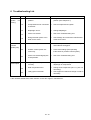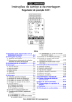
1
Holter Regelarmaturen GmbH & Co. KG
Valves for heating, ventilation, air conditioning – for industrial and power plant use
Operating Manual
Pneumatic membrane actuators
Types PA-N 160 and PA-N 280
0508 / 112966 / HORA / GB
PA-N160+280_GB_0508
Contents
1 General information ................................................................................3
1.1 Manufacturer’s contact address .......................................................................... 3
1.2 Reservation of changes and copyright ............................................................... 3
1.3 Validity of this user manual.................................................................................. 3
1.4 Safety information and regulations ..................................................................... 4
1.4.1 Meaning of the information ................................................................................ 4
1.4.2 General safety information ................................................................................ 4
1.4.3 Qualified personnel ........................................................................................... 4
1.5 Warranty................................................................................................................. 5
2 Transport, storage and handling............................................................5
3 Description, technical data .....................................................................5
3.1
3.2
3.3
3.4
3.5
Area of application ................................................................................................ 5
Function and mode of operation.......................................................................... 6
Dimension drawing ............................................................................................... 6
Sectional drawing with parts list.......................................................................... 7
Limits for application ............................................................................................ 8
4 Assembly .................................................................................................8
4.1 Installation of the actuator onto the valve........................................................... 9
4.2 Dismantling the actuator off the valve............................................................... 10
4.3 Connection of the control air conduit and components .................................. 10
4.4 Reversal of the operating mode and exchanging spares ................................ 10
4.4.1 PA-N 160 and PA-N 280 without manual positioning ...................................... 10
4.4.2 PA-N 160 and PA-N 280 with manual positioning ........................................... 12
5 Commissioning & Maintenance ...........................................................12
5.1
5.2
Commissioning ................................................................................................... 12
Maintentance ....................................................................................................... 13
6 Error search list.....................................................................................14
2 / 14
1 General information
1.1
Manufacturer’s contact address
Holter Regelarmaturen GmbH & Co. KG
Helleforthstraße 58-60
D - 33758 Schloß Holte-Stukenbrock
Phone:
FAX:
E-Mail:
Internet:
1.2
Postfach 14 60
D – 33751 Schloß Holte-Stukenbrock
+49 – (0) – 5207 – 8903 – 0
+49 – (0) – 5207 – 88 037
[email protected]
http://www.hora.de
Reservation of changes and copyright
The regulations, directives, standards etc. are compliant with the current state of information at the time of
development and are not subject to modification service. They must be applied by the operator at his own
responsibility in their latest valid version.
Concerning all data, information, and illustrations in this manual we reserve the right of technical
modifications and improvements. No claims can be considered for alteration or rework of already delivered
actuator.
The copyright for this operating manual as well as all rights in case of patent awarding or registration of
registered design remains with the manufacturer!
1.3
Validity of this user manual
This user manual is only valid for the actuator types PA-N 160 and PA-N 280 with or without manual
adjustment.
The regulations, directives and information stated in this operating manual are valid for the European
Community. Operators outside the EC must, at their own responsibility, regard the stated rules as practised
basis for safe operation and compare their implementation to the national / regional regulations valid for the
installation location.
In case you require further information, or if special problems occur that are not treated extensively enough
in the operating manual, please contact your supplier / manufacturer directly.
In case of questions, state the data from the type label (see picture 4):
• Man. no. (picture 4 field 1)
• Type (picture 4 field 2)
• Spring (picture 4 field 3)
• Input air pressure (picture 4 field 4)
• Function (picture 4 field 5)
3 / 14
1.4
Safety information and regulations
1.4.1
Meaning of the information
Danger:
1.4.2
•
•
•
•
Means that death, serious personal injury or serious material damage may be incurred
if the respective safety measures are ignored.
Attention:
Means that material damage or adverse environmental influences may occur if this
information is ignored.
NOTE:
Means information concerning a certain advantage if this recommendation is adhered
to.
General safety information
For installation, operation and maintenance of the accessories, the respectively valid regulations
pertaining to maintenance of industrial health and safety, accident prevention as well as the EC
regulations must be observed at the operator’s own responsibility!
Every person given responsibility for one of the measures described in this operating manual must have
read and understood this manual!
Fitting, operating and maintenance staff apply safe working practices at all times and have to avoid any
working methods that could in any way endanger persons or damage the actuators or other assets.
Before beginning any maintenance and / or repair work the electric leads leading to the valve actuator
must be disconnected in accordance with EC directives by qualified staff. The valve also needs to be
depressurised, cooled down and emptied.
Danger:
During operation, the valve is under pressure and temperature.
If the warning information is ignored, death or serious personal injuries or material damage
may be incurred.
Only qualified staff (see 1.4.3) may work on or around these actuators. The personnel must be
thoroughly familiar with all warnings, the installation and the maintenance measures according to this
operating manual.
The perfect and safe operation of the actuators requires appropriate transport, correct storage,
positioning and mounting as well as careful, safety-conscious operation and repair.
•
The above information and the following warnings do not consider possible additional regional, local or
in-company safety regulations and must be complemented by the operator at his own responsibility if
necessary!
1.4.3
Qualified personnel
For the purposes set out in these operating instructions, or warning notices, persons shall be considered
qualified if they are familiar with positioning, mounting and commissioning and the operation or maintenance
of the actuators, and have the usual qualifications for this type of occupation. The necessary and prescribed
qualifications include:
• Training / instruction or authorization to turn on /off circuits and appliances / systems according to EN
60204 (DIN VDE 0100 / 0113) and the standards of safety technology.
• Training or instruction according to the standards of the safety technology concerning care and use of
adequate safety and work protection equipment.
• First Aid training.
4 / 14
1.5
Warranty
The scope and period of warranty is stated in the manufacturer’s “General Terms of Delivery“. The latest
valid issue, at the time of delivery, is decisive.
Amongst others no liability shall be accepted for damages to the actuators arising due to one or more of the
reasons stated below:
• Ignorance or non-observance of this operating manual.
• Insufficiently qualified installation, operating and / or maintenance personnel.
• Natural wear.
• Faulty or negligent treatment of the drives.
• Chemical, electrochemical and / or electrical influences.
Furthermore warranty and manufacturer’s liability is excluded for:
• Non-observance of the maintenance of industrial health and safety standards, accident prevention
regulations, EC and / or other safety regulations.
• Modifications or changes of the actuator that were executed improperly or without manufacturer’s prior
consent.
• Faulty installation, incorrect commissioning and improper operation.
• Inappropriate or improper application, in case of improper use as well as in case of other than the agreed
conditions of use.
The risk in case of a violation of the above restrictions shall be borne, in case of personal or material
damage, exclusively by operator!
2 Transport, storage and handling
During transport and intermediate storage the following points should be observed:
• Until installation, the actuator should be stored in a dry place.
• Temperature for transport and storage should be between –30°C and +80°C.
• The actuator must be protected against external forces (impacts, shocks, vibrations etc.).
• Damage to the corrosion protection (paint, oiled surfaces etc.) must be repaired immediately.
• Intermediate storage for more than 6 months must be avoided.
• If the actuator is already mounted onto a valve please also observe the conditions for transport, storage
and handling of the valve
Please ensure that there is sufficient clearance above the installation location for dismantling and installation.
(See also chapter 3.3)
If the actuator is mounted on a valve, the chain hoists used for fitting the assembly group are to be attached
to the valve. In this process, the construction unit must be secured against rotating or be supported, so that
personal and material damage is avoided.
3 Description, technical data
3.1
Area of application
The pneumatic control actuators are directly mounted to actuate control valves. They are especially suited
for application in control systems of the chemical industry. They achieve high control forces for brief control
times. Also, a safety position in case of control power failure is ensured through the springs.
5 / 14
3.2
Function and mode of operation
By means of the pneumatic actuator pneumatic control signals are converted into a shearing movement. The
necessary reaction force is generated by the pressure springs on membrane plate.
In case of air failure the actuator is reset into the initial position through the spring force.
The operating mode of the drive, spring opens – air closes (SO) or air opens – spring closes (SC) is
achieved depending on the installation of the springs. For actuators already installed in systems the
operating mode can be changed with simple tools without additional parts.
3.3
Dimension drawing
Actuator
type
Stroke
[mm] {in}
Total volume
[dm³] {cu.in}
Stroke volume
[dm³] {cu.in}
10 {0,39}
20 {0,78}
20 {0,78}
PA-N 280
30 {1,18}
0,34 {20,75}
0,5 {30,51}
1,04 {63,46}
1,32 {80,55}
0,16 {9,76}
0,32 {19,52}
0,56 {34,17}
0,84 {51,26}
PA-N 160
Table 1:
5,8 {12,8}
9,1 {20,1}
12,9 {28,4}
16,2 {35,7}
Actuator type PA-N 280 SC and SO without and with manual positioning (structure identical
for PA-N 160)
Operating
mode
FS
PA-N 160
FÖ
FS
PA-N 280
FÖ
Table 2:
Weight with manual positioning
[kg] {lb}
Volumes and weights (total volume equals stroke volume + air volume with relaxed springs)
Picture 1:
Actuator
type
Weight without manual positioning
[kg] {lb}
A (1)
[mm]
{in}
ØB
[mm]
{in}
107
{4,21} 202
127 {7,95}
{5,0}
107
284
{4,21}
{11,1
137
8}
{5,39}
C.
[mm]
{in}
E
[mm]
{in}
F
G
[mm]
{in}
H
[mm]
{in}
ØI
[mm]
{in}
J
[mm]
{in}
K
291
{11,46}
100
{3,94}
M12
15
25
20
19,5
{0,59} {0,98} {0,79} {0,77}
M10
323
{12,72}
Dimensions in pressure-free status for picture 1
6 / 14
(1)
L
NPT
¼/
G¼
M
[mm]
{in}
N
[mm]
{in}
ØO
[mm]
{in}
573
{22,56}
200
{7,87}
160
{6,3}
605
{23,82}
at spring range beginning
3.4
Sectional drawing with parts list
SC
Picture 2:
Position
1
2
3
4
5
6
7
8
10
10.1
10.2
10.3
10.4
10.5
10.6
Table 3:
SO
SC
SO
Actuator type PA-N 160 SC and SO without and with manual positioning (structure identical
for PA-N 280)
Designation
Spindle
Ring divided
Membrane disc
Membranes *
Plate
Axial clamping screw
Tension nut
Threaded pin
Guide, complete *
Guide
Socket
Scraper
Support ring
Square ring
Disk
Position
10.7
11
12
13
14
15
16
17
18
19
20
21
22
Designation
O-ring
Cover bottom
Spring centring sheet
Pressure spring
Cover top
Hexagonal screw
Disk
Hexagonal screw
Hexagonal nut
Groove nut
Column
Coupling
Cylinder screw
30
Spindle
* Spare Parts
Parts list for picture 2
7 / 14
Position
31
32
33
34
35
36
37
38
39
40
41
42
43
44
45
Designation
Grooved clamping pin
Leadscrew
Hexagonal screw
Rotary guard
Bridge
Axial needle ring
Threaded bush
Hexagonal nut
Bridge lid
Cylinder screw
Threaded pin
Hand wheel
Flap
Grease nipple
Locking bolt
3.5
Limits for application
The actuators are designed to be used in ambient temperatures between -30°C and +80°C. The temperature
limit is due to the material of the membranes and seals.
The pressure springs as well as the membranes are designed for 2 million strokes.
The maximum operating pressure of the actuators is 6.0 bar.
Actuator
type
Membrane Stroke
Spring area Number of Spring closes / Spring opens /
surface
springs
Closing force Closing force [N] {lbf} with input air pressure [bar] {psi}
[cm²] {sq.in} [mm] {in} [bar] {psi}
[N] {lbf}
1,5
2,0
2,5
3,5
4,0
5,0
6,0
10
{0,39}
PA-N 160
160
{24,8}
20
{0,78}
20
{0,78}
PA-N 280
280
{43,4}
30
{1,18}
Table 4:
0,6-0,8
{8,7-11,6}
0,9-1,2
{13,0-17,4}
1,2-1,6
{17,4-23,2}
1,8-2,4
{26,1-34,8}
0,6-1,0
{8,7-14,5}
0,9-1,5
{13,0-21,7}
1,2-2,0
{17,4-29,0}
1,8-3,0
{26,1-43,5}
0,6-0,7
{8,7-10,1}
0,9-1,2
{13,0-17,4}
1,2-1,5
{17,4-21,7}
1,8-2,3
{26,1-33,3}
2,5-3,2
{36,2-46,4}
0,6-0,8
{8,7-11,6}
0,9-1,3
{13,0-18,8}
1,2-1,7
{17,4-24,6}
1,8-2,5
{26,1-36,2}
2
3
4
6
2
3
4
6
2
3
4
6
6
2
3
4
6
960
{215}
1440
{323}
1920
{431}
2880
{647}
960
{215}
1440
{323}
1920
{431}
2880
{647}
1680
{377}
2520
{566}
3360
{755}
5040
{1133}
7000
{1574}
1680
{377}
2520
{566}
3360
{755}
5040
{1133}
1120
{251}
480
{107}
1920
{431}
1280
{287}
640
{143}
2720
{611}
2080
{467}
1460
{328}
160
{35}
2400
{539}
1600
{359}
800
{179}
800
{179}
1600
{359}
800
{179}
2240
{503}
840
{188}
3640
{818}
2240
{503}
1400
{314}
5040
{1133}
3640
{818}
2800
{629}
560
{125}
1960
{440}
560
{125}
3360
{755}
1960
{440}
840
{188}
4760
{1070}
3360
{755}
2240
{503}
4320
{971}
3680
{827}
3040
{683}
1760
{395}
4000
{899}
3200
{719}
2400
{539}
800
{179}
7840
{1762}
6440
{1447}
5600
{1258}
3360
{755}
2800
{629}
7560
{1699}
6160
{1384}
5040
{1133}
2800
{629}
5120
{1151}
4480
{1007}
3840
{863}
2560
{575}
4800
{1079}
4000
{899}
3200
{719}
1600
{359}
9240
{2077}
7840
{1762}
7000
{1573}
4760
{1070}
4200
{944}
8960
{2014}
7560
{1699}
6440
{1447}
4200
{944}
6720
{1510}
6080
{1366}
5440
{1222}
4160
{935}
6400
{1438}
5600
{1258}
4800
{1079}
3200
{719}
12040
{2706}
10640
{2391}
9800
{2203}
7560
{1699}
7000
{1573}
11760
{2643}
10360
{2329}
9240
{2077}
7000
{1573}
8320
{1870}
7680
{1726}
7040
{1582}
5760
{1294}
8000
{1798}
7200
{1618}
6400
{1438}
4800
{1079}
14840
{3336}
13440
{3021}
12600
{2832}
10360
{2329}
9800
{2203}
14560
{3273}
13160
{2958}
12040
{2706}
9800
{2203}
Actuating forces
4 Assembly
Danger !
Before beginning any work, please observe:
• Switch electrical components voltage-free and secure against unintentional restart!
• Work properly and following the EC safety regulations as well as the warnings and
information in this operating manual.
• Ensure that the pipe section where the valve is located is pressure-free.
• Allow the valve to cool down to about room temperature.
8 / 14
4.1
Installation of the actuator onto the valve
For diagonal installation position the actuator must be installed in a way that the position of the columns
generate the maximum resistance torque (see picture 3).
Picture 3:
Position of the columns for horizontal installation
From a diagonal position of 30° of a vertical position it is recommended to support the actuator weight. This
is important if vibration of the pipe system is likely.
In the following installation is carried out:
• Bring the cone spindle of the valve into the lower fitting position.
• Place the actuator on without tightening the nuts (on column 20) for fastening tightly.
• Connect control air conduit to the actuator (see chapter 4.3)
• if a manual positioning exists, the turning safeguard (34) must be moved with the manual wheel (42) to
zero position (marked by a sign on column 20).
• For a drive with operating mode SC, set the desired starting point (e.g. 1.1 bar).
For a drive with operating mode SO, drive out the stroke until the actuator spindle comes to a halt closely
before the valve spindle.
Danger: Please ensure that no compressed air can unintentionally escape from the actuator.
A pressure drop in the actuator may lead to a pre-tension between the valve and the actuator
spindle (1), blowing off the coupling (21) (when cylinder screws (22) are removed).
•
•
•
NOTE: For drives with manual positioning the actuator spindle (1) can also be brought into fitting
position via manual positioning.
In the respective actuator position, connect valve and actuator spindle (1) by means of coupling (21 and
22), observing that the threads fully catch.
No tighten the nuts that fasten the columns (20) on the valve.
Put manual positioning (if available) into 0 position. Turn the manual wheel to the extend that the turning
safeguard (34) is at the same level as the marking (sign on column 20).
9 / 14
4.2
•
Dismantling the actuator off the valve
Move actuator into central position by means of air pressure.
Danger: Please ensure that no compressed air can unintentionally escape from the actuator.
A pressure drop in the actuator may lead to a pre-tension between the valve and the actuator
spindle (1), blowing off the coupling (21) (when cylinder screws (22) are removed).
•
•
•
•
•
4.3
NOTE: For drives with manual positioning the actuator spindle (1) can also be brought into fitting
position via manual positioning.
Loosen cylinder screws (22) and take coupling (21) off valve and actuator spindle (1).
Relax actuator again by lowering control pressure or bringing the manual positioning into zero position
(turning safeguard (34) and marking on column (20) on the same level).
Disconnect control air conduit from actuator (see chapter 4.3).
Remove fastening nuts on the columns (20). Secure actuator against dropping.
Take actuator off valve.
Connection of the control air conduit and components
Danger: When installing or dismantling the control air conduit please observe that it is pressurefree, as otherwise parts may be blown off when loosening the connections.
For operating mode SC, the control air conduit must be connected to the bottom cover and for operating
mode SO to the top cover. The connecting thread is NPT ¼ or G ¼.
Attention:The control air conduit may only be impinged with control pressure on the opposite side of the
springs (pressure room). The connecting drill hole on the spring side must be closed with the
supplied stopper, so that dirt cannot enter and air can escape during movement.
If an existing position regulator is dismantled and re-installed, please ensure that the position of the regulator
is not changed. If the position regulator is exchanged the parameters for the new one must be adjusted to
the old ones. The nominal stroke must not be exceeded.
4.4
Reversal of the operating mode and exchanging spares
For all the installations carried out here, the actuator must be taken off the valve (see chapter 4.2). If the
operating mode or the spring force has been altered, the type label must also be altered.
4.4.1
PA-N 160 and PA-N 280 without manual positioning
The following steps are necessary to dismantle the actuator:
• Remove hexagonal screws short (15) and the respective nuts (18) and washers (16) from the covers (11
and 14).
• Loosen hexagonal screws long (17) evenly until the pre-tension of the pressure springs (13) has been
relaxed completely. Then remove them along with the respective nuts (18) and washers (16).
10 / 14
•
•
For operating mode SO: Remove top cover (14). Pull the spindle components with the braced parts (1 –
8) from the cover bottom (11). Remove the spring centring sheets (12) and the pressure springs (13)
from the cover bottom (11). If the guide is to be replaced (10), undo the groove nut (19) and pull the
guide (10) from the cover bottom (11).
Dismantling of the spindle with braced parts (1 – 8) (Necessary when exchanging the membranes (4) or
when changing the operating mode): Loosen threaded pin (8) to the extend that the thread with the
tension nut (7) is free. Turn tension nut (7) onto the axial tension screw (6) until the upper membrane
disk (3) releases the split rings (2). Remove split rings (2) from spindle (1). Pull membrane disc (3),
membranes (4), plate (5) and axial tension screw with tension nut and threaded pin (6 - 8) off the spindle
(1).
For operating mode SC: Remove cover top (14), spring centring sheets (12) and pressure springs (13).
Pull spindle components with screwed-on parts (1 – 8) from cover bottom (11). If the guide is to be
replaced (10), undo the groove nut (19) and pull the guide (10) from the cover bottom (11).
Dismantling of the spindle with screwed-on parts (1 – 8) (Necessary when exchanging the membranes
(4) or when changing the operating mode): Loosen threaded pin (8) to the extend that the thread with the
tension nut (7) is free. Turn tension nut (7) onto the axial tension screw (6) until the upper membrane
disk (3) releases the split rings (2). Remove split rings (2) from spindle (1). Pull membrane disc (3), axial
tension screw with tension nut and threaded pin (6 - 8), plate and (5) membranes (4) off the spindle (1).
The following steps are necessary to install the actuator:
• Clean all parts and check them for damage. If necessary, re-work parts or replace with original parts.
• If necessary, plug guide (10) into cover bottom (11). Ensure that the O-ring (10.7) is not forgotten.
Fasten with groove nut (19).
• For operating mode SO: Insert lower split rings (2) into the spindle (1). Push lower membrane disc (3),
axial tension spring with tension nut and threaded pin (6 – 8), the plate (5), the membranes (4) and the
upper membrane disc (3) onto the spindle (1). Insert upper split rings (2) into the spindle (1). Brace the
system by twisting apart the axial tension screw (6) and tension nut (7). Tighten threaded pin (8) to
secure the connection. Insert lower spring centring sheet (12), pressure springs (13) evenly spread
across the diameter and the upper spring centring sheet (12) into the cover bottom (11). Insert spindle
with braced parts (1 – 8) into cover bottom (11). Put on cover top (14). Put hexagonal screws long (15)
with one washer each (16) evenly spread across the diameter into the actuator from the top. From
below, put on the disc (16) and hexagonal nuts (18). Evenly tighten hexagonal nuts (18) until the two
covers (11 and 14) are on top of each other. If the stopper is not in the cover top (14), plug it in.
• For operating mode SC: Insert lower split rings (2) into the spindle (1). Push lower membrane disc (3),
membranes (4), plate (5), axial tension screw with tension nut and threaded pin (6 – 8) and upper
membrane disc (3) onto spindle (1). Insert upper split rings (2) into the spindle (1). Brace the system by
twisting apart the axial tension screw (6) and tension nut (7). Tighten threaded pin (8) to secure the
connection. Insert spindle with braced parts (1 – 8) into cover bottom (11). Place the lower spring
centring sheet (12), pressure springs (13) evenly spread across the diameter and the upper spring
centring sheet (12) onto the plate (5). Put on cover top (14). Put hexagonal screws long (15) with one
washer each (16) evenly spread across the diameter into the actuator from the top. From below, put on
the disc (16) and hexagonal nuts (18). Evenly tighten hexagonal nuts (18) until the two covers (11 and
14) are on top of each other. If the stopper is not in the cover bottom (11) plug it in.
• Mount the other hexagonal screws (17) with the washers (16) and the hexagonal nuts (18) and tighten
evenly.
11 / 14
4.4.2
PA-N 160 and PA-N 280 with manual positioning
The following steps are necessary to dismantle the actuator:
• Bring the manual positioning in zero position (turning safeguard (34) and marking on the column (20) at
the same level). To do so, first unlock drop-in pin (45).
• Push grooved clamping pin (31) out of the spindle (30).
• Unscrew hexagonal nuts (38) off the manual positioning columns (20) and remove the whole of the
upper part of the manual positioning.
• The further dismantling procedure is the same as chapter 4.4.1.
The following steps are necessary to install the actuator:
• Clean all parts and check them for damage. If necessary, re-work parts or replace with original parts.
• Installation is initially the same as the installation according to chapter 4.4.1.
• Place the upper part of the manual positioning (35 – 45) onto the columns (20) and fasten with the
hexagonal nuts (38).
• Loosen hexagonal screws (33) to the extend that the turning safeguard (34) on the threaded spindle (32)
can turns.
• Turn the threaded spindle (32) to the extend that the hole for the grooved clamping pin (31) in the
spindle (30) is visible through the slits in the threaded spindle (32).
Attention: The spindle (30) must not be twisted, as otherwise damage to the membrane may occur
•
•
(4).
Press grooved clamping pin (31) into the spindle (30), so that it evenly protrudes from the threaded
spindle (32).
Tighten hexagonal nuts (33) with 20 Nm to tighten the turning safeguard (34).
5 Commissioning & Maintenance
5.1
Commissioning
If the actuator is equipped with a manual positioning, it must be brought into zero position (turning safeguard
(34) and marking on the column (20) at the same level). To do so, unlock drop-in pin (45) and turn the
manual wheel (42). If the suitable position is reached, the drop-in pin (45) engages again.
To ensure faultless operation, the control air necessary for operation should be prepared by a maintenance
unit. If the actuator is operated at temperatures blow zero, dry control air must be used.
12 / 14
5.2
Maintentance
The pneumatic actuators are low-maintenance.
The guide (10) and the membranes (4) are consumables have to be replaced if necessary.
To ensure continuous readiness for use of the manual positioning, we recommend to check the greasing
situation of the threaded spindle (32) every 3 months and, if necessary, put grease directly onto the thread.
The spindle is lubricated at the factory. For this the lubricant KLÜBERPLEX BE 31-502 by
KLÜBER/LUBRICATION is used. When using a different, at least equivalent lubricant, all parts that are in
contact with the lubricant must be cleaned thoroughly before re-lubricating, so that mixing and possible
reaction of the two lubricants is excluded. As alternative lubricant we recommend Oest EP by Oest.
Attention: When using other lubricants or when mixing different lubricants the manufacturer
shall not be liable for possible sequential damage.
When ordering spare parts, state the information given on the type label (see picture 4):
• Man. no. (picture 4 field 1)
• Type (picture 4 field 2)
• Spring (picture 4 field 3)
• Input air pressure (picture 4 field 4)
• Function (picture 4 field 5)
Picture 4:
Type plate
13 / 14
6 Error search list
error
No.
Actuator
1.1
spindle
not
moving
Actuator
spindle
moves jerkily
High air
consumption
Possible causes
Measures
•
Manual positioning is not in
zero position.
•
Bring manual positioning into zero position
(see chapter 5.1)
1.2
•
Compressed air is not in
contact with actuator.
•
Check compressed air system.
1.3
•
Ruptured membrane.
•
Exchange membranes.
1.4
•
Valve cone jammed.
•
See error search list for the valve.
1.5
•
Control force is too weak for the •
valve.
2.1
•
There is too little compressed
air.
2.2
•
Control regulator set incorrectly. •
2.3
•
Valve cone has seized slightly
due to dirt particles.
•
See error search list for the valve.
3.1
•
Membranes not pressed in
properly.
•
Re-tighten hexagonal nuts (18) until
membranes pressed in properly (4).
3.2
•
Seals worn.
•
Exchange guide (10) and/or membranes (4).
•
Inflow conduits to actuator
leaking.
•
Check inflow conduits for leaks and replace
or seal if necessary.
3.3
•
Check dimension or contact manufacturer of
the overall system.
Check compressed air system for damage
and sufficient flow.
Correction of the settings (see operating
manual control regulator).
If the measures described above do not result in a satisfying outcome, the supplier / manufacturer must be
notified.
14 / 14
Holter Regelarmaturen GmbH & Co. KG
Heizungs-, Lüftungs-, Klimaarmaturen - Industrie- und Kraftwerksarmaturen
Operating Instructions
Pneumatic Actuators
Type PA-N 540 – PA-N 2160
0405 / 111503 / HORA / GB
PA-N 540-2160_GB_0405.doc
Contents
Contents........................................................................................................3
1 General Information ................................................................................4
1.1 Manufacturer's Contact Address..........................................................................4
1.2 Modification Rights & Copyright ..........................................................................4
1.3 Validity of Operating Instructions ........................................................................4
1.4 Safety Instructions & Regulations........................................................................5
1.4.1 Significance of Instructions ................................................................................5
1.4.2 General Safety Instructions................................................................................5
1.4.3 Qualified Personnel............................................................................................5
1.5 Warranty .................................................................................................................6
2 Transportation, Storage & Handling ......................................................7
3 Specification, Technical Data.................................................................8
3.1
3.2
3.3
3.4
Application .............................................................................................................8
Function & Operation ............................................................................................8
Section Drawings with Piece Lists .......................................................................8
Limits of Application ...........................................................................................11
4 Assembly ...............................................................................................12
4.1 Fitting the Actuator to the Valve.........................................................................13
4.2 Removing the Actuator from the Valve ..............................................................14
4.3 Connecting the Control Air Pipe & Add-on Parts.............................................14
4.4 Operating Mode Reversal & Fitting Spare Parts ...............................................14
4.4.1 PA-N 540 & PA-N 1080 without Manual Control...............................................14
4.4.2 PA-N 540 & PA-N 1080 with Manual Control ...................................................16
4.4.3 PA-N 2160 with & without Manual Control........................................................17
5 Commissioning & Maintenance ...........................................................18
5.1
5.2
Commissioning ....................................................................................................18
Maintenance .........................................................................................................18
6 Troubleshooting List.............................................................................19
3 / 19
1 General Information
1.1
Manufacturer's Contact Address
Holter Regelarmaturen GmbH & Co. KG
Helleforthstraße 58-60
D -33758 Schloß Holte-Stukenbrock
Tel. :
FAX
Email:
Website:
Postfach 14 60
D – 33751 Schloß Holte-Stukenbrock
+49 – (0) – 5207 – 8903 – 0
+49 – (0) – 5207 – 88 037
[email protected]
http://www.hora.de
1.2 Modification Rights & Copyright
The regulations, guidelines, standards etc. cited in these Operating Instructions comply with the latest
information status during their production and we do not provide an updating service. The operator is
responsible for using the latest valid edition in each case.
The right to technical modifications and improvements is reserved at all times with regard to all data,
information and illustrations in these Operating Instructions. Any claim to modification or improvement to
yokes already supplied is excluded.
Copyright to these Operating Instructions and also all rights in the event of patent award or design
registration remain with the manufacturer!
1.3 Validity of Operating Instructions
These Operating Instructions only apply to actuator types PA-N 540, PA-N 1080 and PA-N 2160 with or without
manual control.
The regulations, guidelines and tips quoted in these Operating Instructions apply to the European
Community. Operators outside the EC are responsible for considering the regulations listed as a practical
basis for safe handling and for measuring their effectiveness against the regional / national regulations which
are applicable to the installation site.
Should you require further information or should particular problems arise which are not dealt with in
sufficient detail in these Operating Instructions, you may request the necessary information directly from the
supplier / manufacturer.
In the event of queries, please quote the data on the nameplate (see Fig. 6):
• Fabrication No. (Fig. 6 Box 1)
• Type (Fig. 6 Box 2)
• Spring (Fig. 6 Box 3)
• Air supply pressure (Fig. 6 Box 4)
• Function (Fig. 6 Box 5)
4 / 19
1.4 Safety Instructions & Regulations
1.4.1 Significance of Instructions
Danger:
Caution:
Note:
Means that death, serious injury or considerable damage to property can occur if the
relevant precautions are not taken.
Means that damage property or the environment can occur if this advice is not
adhered to.
Means a potential advantage to the user if the recommendation is acted upon.
1.4.2 General Safety Instructions
•
•
•
•
It is the operator's responsibility to observe the current Health & Safety, Accident Prevention and EC
Guidelines for installation, operation and maintenance!
Every person, who is entrusted with any of the procedures specified in these Operating Instructions,
must have read and understood these Operating Instructions!
Installation, operating and maintenance personnel shall apply safe working practices for all procedures
and refrain from using any practice which jeopardises the safety of personnel or damages the actuators
or other material assets in any way whatsoever.
Before beginning any maintenance and / or repair work the electric leads leading to the valve must be
disconnected in accordance with EC directives by qualified staff. The valve also needs to be
depressurised, cooled down and emptied.
Danger
The valve is under pressure and temperature during operation.
Death, serious physical injuries or material damage may occur, if the warning notices are not
observed.
Only qualified personnel (see Chapter 1.4.3) may work on or near these actuators. These personnel
must be completely familiar with all safety precautions, installation and maintenance procedures in
accordance with these Operating Instructions.
The perfect and safe operation of the actuators requires appropriate transport, correct storage,
positioning and mounting as well as careful, safety-conscious operation and repair.
•
The above instructions and the following warning notices do not take into account any additional
regional, local or company safety regulations and the operator is responsible for any additions as
required!
1.4.3
Qualified Personnel
For the purposes set out in these operating instructions, or warning notices, persons shall be considered
qualified if they are familiar with positioning, mounting and commissioning and the operation or maintenance
of these actuators, and have the usual qualifications for this type of occupation. The following are considered
to be necessary or prescribed qualifications:
• Education / training or authorisation to connect and disconnect circuits and equipment / systems in
accordance with EN 60204 (DIN VDE 0100 / 0113) and in accordance with safety standards.
• Education or training in accordance with safety standards in the care and utilisation of appropriate safety
and protective equipment.
• First aid training.
5 / 19
1.5 Warranty
The extent and duration of a guarantee is stated in the Manufacturer's "General Terms & Conditions of
Supply". The latest edition valid at the time of delivery is decisive in each case.
Amongst others no liability shall be accepted for damages to the actuators arising due to one or more of the
reasons stated below:
• Ignorance or non-observation of these Operating Instructions.
• Inadequately qualified installation, operating and / or maintenance personnel.
• Fair wear and tear.
• Improper or negligent handling of actuators.
• Chemical, electrochemical and / or electrical influences.
Furthermore, the manufacturer's guarantee and liability are excluded in the event of:
• Non-observance of Health & Safety, Accident Prevention and EC and / or other safety regulations.
• Inappropriate changes or modifications to the actuator or those carried out without the manufacturer's
approval.
• Faulty installation, incorrect commissioning and improper operation.
• Inappropriate or improper utilisation, utilisation not in accordance with specification or any operating
conditions other than those agreed.
The risk of physical and / or material damage in the event of infringement of the above restrictions is the sole
responsibility of the operator!
6 / 19
2 Transportation, Storage & Handling
The following points should be observed during transportation and intermediate storage:
• The actuator should be stored in a dry environment until installation.
• The transportation and storage temperature should be between -30°C and +60°C.
• The actuator should be protected against external forces (jolting, impact, vibrations etc.).
• Damages to the corrosion proofing (coating, oiled surfaces etc.) are to be repaired immediately.
• Intermediate storage for more than 6 months is to be avoided at all costs.
• If the actuator is already fitted to a valve, the transportation, storage- and handling conditions for the
valve shall also be observed
It shall be ensured that lifting eyes for chain hoists are available at the correct height above the installation
site. It would be even better if sliding rails or swivel arms with hoisting gear were available at the place of
installation.
Fig. 1 gives examples of handling possibilities for fitting the actuators.
Fig. 1: Actuator Handling
If the actuator is mounted on a valve, the chain hoists used for fitting the subassembly are to be attached to
the valve.
7 / 19
3 Specification, Technical Data
3.1 Application
Pneumatic control actuators are designed directly for actuating control valves. They are particularly suitable
for utilisation in control systems in the chemical industry. They achieve high actuating powers with short
actuating times. A safety position is also assured in the event of actuating pressure failure by the springs.
3.2 Function & Operation
Pneumatic actuating signals are converted into thrust motion by the pneumatic piston actuator. The required
return force is produced by the pressure springs located on the diaphragm disc.
In the event of air supply failure, the actuator is reset to the default position by spring force.
The actuator mode of operation, i.e. spring opens – air closes (SO) or air opens – spring closes (SC) is
achieved depending on the mounting of the springs. The mode of operation of actuators already fitted to
systems can be changed without additional components using simple tools.
3.3 Section Drawings with Piece Lists
Operation
SO
Operation
SC
SO
SC
Fig. 2: Actuator Type PA-N 540 SO & SC without and with Manual Control
8 / 19
Operation
SO
Operation
SC
SO
SC
Fig. 3: Actuator Type PA-N 1080 SO & SC without and with Manual control
9 / 19
Operation
SO
Operation
SC
SO
SC
Fig. 4: Actuator Type PA-N 2160 SO & SC without and with manual control
10 / 19
Item
1
2
3
4
5
6
7
8
9
10
10.1
10.2
10.3
10.4
11
11.1
11.2
12
13
14
15
16
17
18
19
20
21
22
23
24
25
Table 1:
Designation
Item
Spindle
26
Bushing
27
O-Ring *
28
Disc
29
Diaphragm *
30
Disk
Nut
Headless pin
34
Support
35
Guide complete: *
36
Guide
37
Bush
38
O-ring
39
Seal element
40
Screw connector complete: *
41
Screw connections
42
Bush
43
Lower casing complete
44
Ring
45
Pressure spring
46
Pressure spring
47
Upper casing complete
48
Ring
49
Hexagonal screw long
50
Hexagonal screw short
51
Disk
52
Hexagon nut
53
Coupling
54
Cheese-head screw
55
Reducing nipple
56
Stopper
57
* = spare parts
Piece List for Figs. 2 to 4
Designation
Spindle
Adjustment washer
Casing PA-N 2160
U-Seal-disc
Hexagon head cap screw
Manual control
Screw connections
Spindle
Housing
Ring
Headless pin
Stroke indicator
Leadscrew
Housing cover
Cheese head screw
Manual control support
Bridge
Cheese head screw
Axial Needle Bearing
Threaded bush
Bridge cover
Cheese-head screw
Hand wheel
Headless pin
Lubricating nipple
Locking bolt
Metal
Hexagonal screw
Gearbox complete
Cheese-head screw
The pressure springs and the diaphragms are designed for over 1 million up-and-down strokes.
3.4 Limits of Application
The actuators are designed to be used in ambient temperatures between -30°C and +60°C. The temperature
limit is determined by the diaphragm and seal materials.
The maximum operating pressure of the actuators is 6.0 bar. To calculate the actuator force, the diaphragm
surface area is multiplied by the spring pressure or the operating pressure minus the equivalent spring
pressure.
Example: Actuator PA-N 1080 SC with a spring range of 1.6 – 3.9 bar and an operating pressure of 6 bar
Closing power of spring with extended spindle: F = 108000 mm² * 0.16 N/mm² = 17280 N
Closing power of spring with retracted spindle: F = 108000 mm² * 0,39 N/mm² = 42120 N
Opening power by operating pressure at starting point: F = 108000 mm² * (0.6 – 0.16) N/mm² = 47520 N
Opening power by operating pressure at end point: F = 108000 mm² * (0.6 – 0.39) N/mm² = 22680 N
11 / 19
Table 2 lists standard actuators with their application limits.
Drive
Diaphragm
surface area
Control
pressure
connection
[cm²]
PA-N 540
540
G½
Approx. weight
[kg]
with manual
without
control
manual
control
30
52
Stroke
Spring range
[mm]
[bar]
30
0.7 – 1.0
1.4 – 2.0
2.1 – 3.0
0.6 – 1.3
1.1 – 2.6
1.7 – 3.9
0.8 – 1.3
1.1 – 1.9
1.9 – 3.2
0.7 – 1.6
0.9 – 2.3
1.6 – 3.9
0.8 – 1.3
1.1 – 1.9
1.9 – 3.2
0.7 – 1.6
0.9 – 2.3
1.6 – 3.9
50
PA-N 1080
1080
G½
95
120
60
80
PA-N 2160
2160
G½
180
215
60
80
Table 2:
Actuator Application Limits
4 Assembly
Danger!
Please observe before commencing any work:
• Disconnect electrical components and secure against accidental switching-on!
• Work properly and safely in accordance with EC regulations and the warnings and advice
given in these operating instructions.
• Depressurise the pipe section in which the valve sits.
• Allow the valve to cool down to approx. room temperature.
12 / 19
4.1 Fitting the Actuator to the Valve
For installation at an angle, fit the actuator so that the maximum resistance force is achieved by the position
of the supports (see Fig. 5).
Fig. 5: Position of Supports for Horizontal Installation
Supporting the actuator weight is recommended starting from an angle of 30° from the vertical. This applies
in particular if vibrations in the pipework system are anticipated.
Installation procedure:
• Bring the valve cone spindle into the lower seat position.
• Mount the actuator without tightening the nuts and screws for fixing to the valve crossbar.
• Connect the control air pipe to the actuator (see Chapter 4.3)
• If there is a manual control, fit the stroke indicator on the housing (36 & 39) between the grooves on the
manual control supports (43).
• Set the required starting point (e. g. 1.1 bar) for an actuatror with SC operation.
For an actuator with SO operation, extend the stroke until the actuator spindle comes to a standstill just
before the valve spindle.
•
•
Danger Ensure that compressed air cannot escape accidentally from the actuator. A pressure
drop in the actuator can cause prestress between the valve and actuator spindle (1) and ejection
of the coupling (22) (if the cheese-head screws (23) have been removed).
Note: With actuators with manual control, the actuator spindle (1) can also be brought into the correct
position via the manual control.
Connect the valve and actuator spindle (1) via the coupling (22 & 23) in the respective actuating position,
whereby it should be ensured that the threads are fully engaged and that the stroke indicator arrow
points to the lowest mark on the stroke indicator plate when the actuator is closed.
Now tighten the nuts and screws to fix the actuator to the valve crossbar.
13 / 19
4.2 Removing the Actuator from the Valve
•
•
•
•
•
•
•
Move the actuator into the central position using air pressure.
Danger Ensure that compressed air cannot escape accidentally from the actuator. A pressure
drop in the actuator can cause prestress between the valve and actuator spindle (1) and ejection
of the coupling (22) (if the cheese-head screws (23) have been removed).
Note: With actuators with manual control, the actuator spindle (1) can also be brought into the correct
position via the manual control.
Undo the cheese-head screws (23) and remove the coupling (22) from the valve and actuator spindle
(1).
Depressurise the actuator once more by reducing the control pressure and bringing the manual control
into the zero position (stroke indicator on housing (36 & 39) between the grooves on the manual control
supports (43)).
Disconnect control air pipe from the actuator (see Chapter 4.3).
Protect the actuator (see Chapter 2)
Remove the fixings nuts and screws from the actuator supports (9).
Remove the actuator from the valve.
4.3 Connecting the Control Air Pipe & Add-on Parts
Danger: When fitting and removing the control air pipe, ensure that it is depressurised, otherwise
parts can be ejected when undoing the connections.
With SC operation, connect the control air pipe to the lower casing, and with SO operation to the upper
casing. The connecting thread is G ½.
Caution: The control air pipe may only be loaded with actuating pressure on the side opposite the springs
(pressure chamber). The connecting bores on the spring side must be sealed with the reducing
nipple (24) and stopper (25) so that no dirt can get in and air can escape during operation.
If an existing position control system is removed and refitted, ensure that the position of the control is not
changed. If the position control system is changed, the parameters of the new system shall be adapted to
the old. The nominal stroke may not be exceeded.
4.4 Operating Mode Reversal & Fitting Spare Parts
The actuator must be removed from the valve for all the fitting jobs undertaken here (see Chapter 4.2).
4.4.1 PA-N 540 & PA-N 1080 without Manual Control
Proceed as follows to dismantle the actuator:
• Remove the short hexagonal screws (19) from the housing.
• Loosen the long hexagonal screws (18) evenly until the preload on the pressure springs (14 and/or 15)
has been dissipated completely. Then remove completely together with the ring (17 only PA-N 1080).
14 / 19
•
•
With SO operation: Remove the upper casing (16). Remove the spindle assembly together with the
screwed parts (1 – 8) from the lower casing (12). Take the ring (13) and the pressure springs (14 and/or
15) from the lower casing (12). Should the guide (10) and/or screw connector (11) need to be renewed,
unscrew the screw connector (11) and remove the guide (10) from the lower casing (12).
Dismantling the spindle together with screwed parts (1 – 8) (Necessary when changing the O ring (3) or
changing the mode of operation): Loosen the setscrew (8) so that the thread of the nut (7) is visible.
Unscrew the nut (7) from the spindle (1). Remove the washer (6), diaphragm (5), disc (4), O ring (3) and
bush (2) from the spindle.
With SC operation: Remove the upper casing (16), the pressure springs (14 and/or 15) and the ring (13).
Remove the spindle assembly together with the screwed parts (1 – 8) from the lower casing (12). If the
guide (10) and/or the screw connector (11) needs to be renewed, unscrew the screw connector (11) and
remove the guide (10) from the lower casing (12).
Dismantling the spindle together with screwed parts (1 – 8) (Necessary when changing the O ring (3) or
changing the mode of operation): Loosen the setscrew (8) so that the thread of the nut (7) is visible.
Unscrew the nut (7) from the spindle (1). Remove the bush (2), O ring (3), disc (4), diaphragm (5) and
washer (6) from the spindle.
Proceed as follows to fit the actuator:
• Clean all parts and inspect for damage. If necessary, rework the parts or replace with original parts.
• If necessary, insert the guide (10) into the upper casing (12). Secure with the screw connector (11).
• With SO operation: Put the bush (2), the O ring (3), the disc (4), the diaphragm (5; ensure that the
diaphragm fabric is on the disc side) and the washer (6) onto the spindle (1). Screw the nut (7) tightly
onto the spindle and secure with the setscrew (8). Place the pressure springs (14 and/or 15) and the ring
(13) onto the lower casing (12). Insert the spindle together with the screwed parts (1 – 8) into the lower
casing (12). Mount the lower casing (16) and the ring (17 only PA-N 1080). Insert the long hexagonal
screws (18) into the actuator from above evenly distributed over the circumference. Push on the washers
(20) and hexagonal nuts (21) from below. Tighten the hexagonal nuts (21) evenly until the pressure
springs (14 and/or 15) are preloaded. If the reducing nipple (24) with the stopper (25) is not in the upper
casing (16), screw it in.
• With SC operation: Put the washer (6), the diaphragm (5; ensure that the diaphragm fabric is on the disc
side), the disc (4), the O ring (3) and the bush (2) onto the spindle (1). Screw the nut (7) tightly onto
spindle and secure with the setscrew (8). Insert the spindle together with the screwed parts (1 – 8) into
the lower casing (12). Put the pressure springs (14 and/or 15) and the ring (13) onto the spindle together
with the screwed parts (1 – 8). Mount the upper casing (16). Insert the long hexagonal screws (18) into
the actuator from above evenly distributed over the circumference. Push on the ring (17 only PA-N 1080),
the washers (20) and hexagonal nuts (21) from below. Tighten the hexagonal nuts (21) evenly until the
pressure springs (14 and/or 15) are preloaded.
If the reducing nipple (24) together with the stopper (25) is not in the lower casing (12), screw it in.
• Insert the short hexagonal screws (19) into the remaining holes from above. Push on the washers (20)
and hexagonal nuts (21). Tighten all hexagonal nuts (21) evenly until the diaphragm (5) is compressed.
15 / 19
4.4.2 PA-N 540 & PA-N 1080 with Manual Control
Proceed as follows to dismantle the actuator:
• Bring the manual control into the zero position (stroke indicator on housing (36 & 39) between the
grooves on the manual control supports (43)) .
• Unscrew the cheese-head screws (42) and move the leadscrew (40) upwards.
• With SO operation: Loosen the setscrew (38) so that the thread of the ring (37) is visible. Unscrew the
ring (37) from the spindle (35).
• With SC operation: Connect the air pipe to the lower casing (12). Move the actuator into the central
position using air pressure.
•
•
•
•
Danger: Ensure that compressed air cannot escape accidentally from the actuator. A pressure
drop can cause compression when removing the ring (37).
Loosen the setscrew (38) so that the thread of the ring (37) is visible. Unscrew the ring (37) from the
spindle (35). Depressurise the actuator once more by reducing the air pressure. Disconnect the air pipe
from the actuator (see Chapter 4.3).
Remove the short hexagonal screws (19) from the housing.
Loosen the hexagonal screws (18) evenly until the preload on the pressure springs (14 and/or 15) is
dissipated completely. Then remove completely together with the ring (17 only PA-N 1080).
With SO operation: Remove the upper casing (12). Remove the spindle assembly together with screwed
parts (1 – 6 + 8 + 35) from the lower casing (12). Take the ring (13) and the pressure springs (14 and/or
15) from the lower casing (12). Should the guides (10) and/or screw connectors (11) need to be
renewed, unscrew the screw connector (11 & 34 for PA-N 1080 at the top) from both casings and remove
the guides (10) from the casings (12).
Dismantling the spindle together with screwed parts (1 – 6 + 8 + 35) (Necessary when changing the O
ring (3) or changing the mode of operation): Loosen the setscrew (8) so that the spindle thread (35) is
visible. Unscrew the spindle (35) on the spindle (1). Remove the washer (6), diaphragm (5), disc (4), O
ring (3) and bush (2) from the spindle.
With SC operation: Remove the upper casing (12), the pressure springs (14 and/or 15) and the ring (13).
Remove the spindle assembly together with screwed parts (1 – 6 + 8 + 35) from the lower casing (12).
Should the guides (10) and/or screw connectors (11) need to be renewed, unscrew the screw connector
(11 & 34 for PA-N 1080 at the top) on both casings and remove the guides (10) from the casings (12).
Dismantling the spindle together with screwed parts (1 – 6 + 8 + 35) (Necessary when changing the O
ring (3) or changing the mode of operation): Unscrew the setscrew (8) so that the spindle thread (35) is
visible. Unscrew the spindle (35) from the spindle (1). Remove the bush (2), O ring (3), disc (4),
diaphragm (5) and washer (6) from the spindle.
Proceed as follows to fit the actuator:
• Clean all parts and inspect for damage. If necessary, rework the parts or replace with original parts.
• If necessary, insert the guides (10) into the casings (12). Secure with screw connector (11 & 34 for PA-N
1080 at the top).
16 / 19
•
•
•
•
•
•
•
With SO operation: Put the bush (2), the O ring (3), the disc (4), the diaphragm (5; ensure that the
diaphragm fabric is on the disc side) and the washer (6) onto the spindle (1). Screw the spindle (35)
tightly onto the spindle and secure with setscrew (8). Place the pressure springs (14 and/or 15) and the
ring (13) on the lower casing (12). Insert the spindle together with the screwed parts (1 – 6 + 8 + 35) into
the lower casing (12). Mount the upper casing (12) and the ring (17 only PA-N 1080). Insert the long
hexagonal screws (18) into the actuator from above evenly distributed over the circumference. Insert the
washers (20) and hexagonal nuts (21) from below. Tighten the hexagonal nuts (21) evenly until the
pressure springs (14 and/or 15) are preloaded. If the reducing nipple (24) with the stopper (25) is not in
the upper casing (12), screw it in.
With SC operation: Put the washer (6), the diaphragm (5; ensure that the diaphragm fabric is on the disc
side), the disc (4), the O ring (3) and the bush (2) onto the spindle (1). Screw the spindle (35) tightly onto
the spindle (1) and secure with setscrew (8). Insert the spindle together with the screwed parts (1 – 6 + 8
+ 35) into the lower casing (12). Put the pressure springs (14 and/or 15) and the ring (13) onto the
spindle together with the screwed parts (1 – 6 + 8 + 35). Mount the upper casing (12). Insert the long
hexagonal screws (18) into the actuator from above evenly distributed over the circumference. Insert the
ring (17 only PA-N 1080), the washers (20) and hexagonal nuts (21) from below. Tighten the hexagonal
nuts (21) evenly until the pressure springs (14 and/or 15) are preloaded.
If the reducing nipple (24) with the stopper (25) is not in the lower casing (12), screw it in.
Insert the short hexagonal screws (19) from above into the remaining holes. Put on the washers (20) and
hexagonal nuts (21). Tighten all hexagonal nuts (21) evenly until the diaphragm (5) is compressed.
With SO operation: Screw the ring (37) onto the spindle (35) and secure with setscrew (38).
With SC operation: Connect the air pipe to the lower casing (12). Move the actuator into the central
position using air pressure.
Danger: Ensure that compressed air cannot escape accidentally from the actuator. A pressure
drop can cause compression when removing the ring (37).
Screw the ring (37) onto the spindle (35) and secure with setscrew (38). Depressurise the actuator once
more by reducing the air pressure. Disconnect the air pipe from the actuator (see Chapter 4.3).
Move the leadscrew (40) downwards. Fasten the housing (36) with the cheese-head screws (42) to the
leadscrew (40). With PA-N 540, ensure that the stroke indicator (39) is fitted appropriately.
Bring the manual control into the zero position (stroke indicator on housing (36 & 39) between the
grooves on the manual control supports (43)).
4.4.3 PA-N 2160 with & without Manual Control
Special fitting tools are required for changing spare parts in the actuator and for changing the mode of
operation. The manufacturer must be consulted prior to installation for this reason.
17 / 19
5 Commissioning & Maintenance
5.1 Commissioning
If the actuator is fitted with a manual control, it shall be brought into the zero position (stroke indicator on
housing (36 & 39) between the grooves on the manual control supports (43)). Open the locking bolt (53) and
turn the handwheel (50 for PA-N 540; on the gearbox (56) for PA-N 1080). Once the correct position has been
reached, the locking bolt (53) can be re-engaged.
In order to ensure trouble-free operation, the control air required for actuation is processed by a maintenance
unit. If the actuator is operated at subzero temperatures, dry control air must be used .
5.2 Maintenance
Pneumatic actuators without manual control are maintenance-free.
O ring (3), diaphragm (5), guide complete (10) and screw connector complete (11) are wearing parts and
must be changed as necessary.
In order to ensure constant availability of the manual control, we recommend checking and, if necessary,
topping-up the lubricant level for the spindle (35) every 3 months.
The spindle is lubricated in the factory. For this the lubricant KLÜBERPLEX BE 31-502 by
KLÜBER/LUBRICATION is used. If using a different but equivalent lubricant, all parts coming into contact
with the lubricant must be cleaned thoroughly prior to using the new lubrication in order to preclude mixing
and any potential reaction of the two lubricants. Oest EP from the Oest company is recommended as an
alternative lubricant. Caution: If using alternative or mixing different lubricants, the manufacturer does
not undertake any guarantee for consequential damages.
Changing the lubricant after 8 – 10 years is recommended:
The manufacturer should be consulted in the event of lubricant change.
Quote the data on the nameplate (see Fig. 6) when ordering spare parts:
• Fabrication No. (Fig. 6 Box 1)
• Type (Fig. 6 Box 2)
• Spring (Fig. 6 Box 3)
• Air supply pressure (Fig. 6 Box 4)
• Function (Fig. 6 Box 5)
Fig. 6: Nameplate
18 / 19
6 Troubleshooting List
Fault
No.
Actuator
1.1
spindle
not
moving
•
Possible Cause
Manual control not in zero
position.
•
Measures
Bring the manual control into the zero
position (see Chapter 5.1)
1.2
•
Compressed air not connected
to actuator.
•
Check compressed air system.
1.3
•
Diaphragm is torn.
•
Change diaphragm.
1.4
•
Valve cone seized.
•
See Valve Troubleshooting List.
1.5
•
Design actuator power is too
weak for the valve.
•
Check design and consult the manufacturer
of the whole valve.
Movement of 2.1
actuator
spindle jerky
•
Too little compressed air.
•
Check compressed air system for damage
and sufficient throughput.
2.2
•
Position control system set
incorrectly.
•
Correct the settings (see Operating
Instructions for position control system).
2.3
•
Valve cone seized slightly due
to dirt particles.
•
See Valve Troubleshooting List.
3.1
•
Diaphragm not compressed
correctly.
•
Tighten hexagonal nuts (21) until the
diaphragm is compressed.
3.2
•
Seal components worn.
•
3.3
•
Leaky pipes to actuator.
•
Change seal components (10 & 11, plus 3 if
necessary).
Check pipes for leaks and change or seal as
necessary.
High air
consumption
If the remedies stated above lead nowhere contact the supplier / manufacturer.
19 / 19