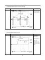
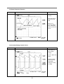
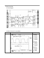
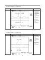
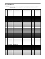
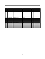
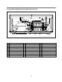
1
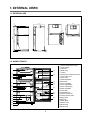
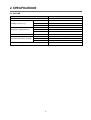
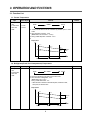
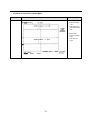
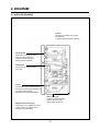
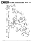
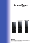
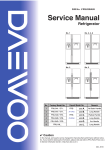
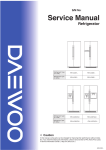
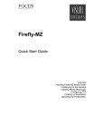
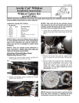
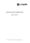
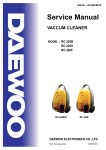
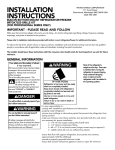
S/M No. : FR631KD012
Service Manual
Refrigerator
Model: FR-631KD
FR-710KR
✔ Caution
: In this Manual, some parts can be changed for improving, their
performance without notice in the parts list. So, if you need the
latest parts information,please refer to PPL(Parts Price List) in
Service Information Center (http://svc.dwe.co.kr).
DAEWOO ELECTRONICS CO., LTD.
http://svc.dwe.co.kr
Jan. 2004
SAFETY AND PRECAUTIONS
1) For starters, be sure to check any chances of the leakage of electricity
2) You could handle a part in the vicinity of electricity after unplugging
3) You should put on rubber glovers to prevent an electric shock on operation test
4) Make sure the rated current, voltage, capacity before using an instrument
5) Keep your wet hands away from the metal goods in the freezer compartment not to be frostbitten
6) Be careful not to let water to permeate the electric part in the machine room
7) with the door open during your working, you might be damaged by that door
8) You should give a tilt to the refrigerator for your safe after removing the breakable goods inside the refrigerator
9) You'd better use cotton gloves if you fix it up around the evaporator
TABLE OF CONTENTS
1. EXTERNAL VIEWS .........................................................................................................................................................2
1-1. EXTERNAL SIZE ...........................................................................................................................................2
1-2. NAME OF PARTS ..........................................................................................................................................2
2. SPECIFICATIONS ...........................................................................................................................................................3
2-1. OUTLINE ........................................................................................................................................................3
3. OPERATION AND FUCTIONS........................................................................................................................................4
3-1. FUNCTION LIST ............................................................................................................................................4
3-2. CIRCUIT & WIRE DIAGRAM .........................................................................................................................7
3-3. CIRCUIT .........................................................................................................................................................8
4. DIAGRAM ......................................................................................................................................................................14
4-1. AIR FIOW DIAGRAM ...................................................................................................................................14
4-2. REFRIGENT CYCLE DIAGRAM ..................................................................................................................15
5. EXPLODED VIEW AND PARTS LIST...........................................................................................................................16
5-1. TOTAL EXPLODED VIEW ...........................................................................................................................16
5-2. TOTAL PARTS LIST ....................................................................................................................................17
5-3. MACHINE ROOM EXPLODED VIEW AND PARTS LIST............................................................................21
1
1. EXTERNAL VIEWS
1-1. EXTERNAL SIZE
810
590
10
12
17.3
589
695
62
38.4
715.1
820
1.1 52
18
96
1084
732
1817.4
820
1-2. NAME OF PARTS
1
u
2
3
4
5
i
p
6
o
7
8
d
9
0
a
s
q
w
f
e
r
t
y
2
1 Freezer Compartment Lamp
2 Shelf Ffreezer
3 Case Icing
4 Guide Icing
5 Ice Box
6 Refrigerator Compartment Lamp
7 Cover Cubic Duct
8 Fresh Case
9 Shelf Refrigerator
0 Deodorant
q Cover Vegetable
w Case Vegetable(B)
e Case Vegetable(A)
r Guide Vegetable
t Front Grille
y Adjustable Foot
u Freezer Pocket Top
i Freezer Pocket Under
o Egg Pocket
p Egg Tray
a Guide Bottle
s Bottle Pocket
d Multi Pocket
f Multi Pocket
2. SPECIFICATIONS
2-1. OUTLINE
DIVISION
CONTENTS
MODEL NAME
USABLE CAPACITY (L)
EXTERNAL DIMENSION( mm)
REFRIGENT
COOLING &CONTROL SYSTEM
FR-631KD
FREEZER
138
REFRIGERATOR
366
TOTAL
504
WIDTH
818
DEPTH
752
HEIGHT
1818
R134a
110
COOLING SYSTEM
Fan Cooling System
DEFROST SYSTEM
Fin Evaporator Forced
DEFORST CONTROL
Automatic Start & Stop
NET WEIGHT (kg)
85
3
3. OPERATION AND FUCTIONS
3-1. Function List
1-1. Freezer Temperature
Input
1. Temperature
Dial
2. F Thermostat
3. ON / OFF
DIFF.
Control Object
1. COMP
2. F-FAN
3. C-FAN
Contents
Remark
1. Freezer temperature is controlled by Freezer Temperature Dial.
Weak
Middle
Strong
2. COMP, F-FAN and C-FAN are controlled by ON/OFF point of each
mode.
3. ON / OFF DIFF of Freezer : 4.0°C
(Middle OFF Point of Freezer : -12.0°C)
4. Strong / Weak Step DIFF of Freezer : 3.0°C
5.
Temperature
-9.0˚C
-12.0˚C
ON
-15.0˚C
-13.0˚C
-16.0˚C
ON/OFF
DIFF
OFF
-19.0˚C
STEP DIFF
Weak
STEP DIFF
Middle
MODE
Strong
1-2. Refrigerator(Fresh Food Compartment) Temperature
Input
Control Object
1. Temperature 1. R-Fan
Dial
2. R Thermostat
3. ON / OFF
DIFF
Contents
Remark
1. efrigerator temperature mode is set by the temperature dial.
Weak
Middle
Strong
2. R-FAN is controlled by ON / OFF point of each mode.
3. ON / OFF DIFF of Refrigerator : 3.0°C
(Middle OFF Point : 0.5°C)
Strong / Weak STEP DIFF : 2°C
* When R-Thermo reaches to R-FAN ON point, R-FAN turns ON ;
OFF point, R-FAN turns OFF.
Temperature
5.5˚C
3.5˚C
ON
1.5˚C
2.5˚C
0.5˚C
STEP DIFF
Weak
ON/OFF
DIFF
-1.5˚C
STEP DIFF
Middle
4
OFF
MODE
Strong
1-3. Defrosting Cycle
Input
1. Accumulated
work time of
COMP
Control Object
1. Defrosting
Mode
Contents
Remark
1. What to consider in determining the defrosting cycle
☞ Total (accumulated) work time of COMP
2. Conditions to start defrosting mode
☞ When total work time of COMP is more than 8, defrosting mode
starts unconditionally.
START
2
4
6
7
8
(Total Work Time of COMP)
1-4. Defrosting Mode
Input
1.Defrosting
Cycle
Control Object
1. COMP
2. F-FAN
3. R-FAN
4. HEATER
Contents
Remark
1. Defrosting Mode
1) COMP, F/R/C-FAN: Control
Control
1) If Bi-Metal is over 10, Heater turns Off.
2) COMP, F/R/C FAN: Off
Heater Defrosting
Pause
1) Pause: 5 minutes
2) COMP, F/C-FAN: Off
3) R FAN: Control
Control
1) COMP, F/R/C FAN: Control
2. Time Chart in Defrosting Mode
Comp
F-FAN
C-FAN
ON
OFF
ON
ON
R-FAN
HTR ON
HTR
HTR Start
HTR Finish Pause Finish/
Pause Star CONTROL
3. Output Control & Limit Time of Each Defrosting Mode
COMP
F-FAN
R-FAN
HEATER
Limit Time
Control
ON/OFF
ON/OFF
ON/OFF
OFF
–
Heate Defrosting
OFF
OFF
OFF
ON
If Bi-metal≥10°C,
HTR turns Off.
Pause
OFF
OFF
ON
OFF
5min.
1) When defrosting starts COMP and F/R/C-FAN turn Off.
2) R Fan is ON/OFF Controlled in Pause mode.
5
Control
ON/OFF
ON/OFF
ON/OFF
OFF
–
1-5. Time Delay of Electrical Parts
Input
1. Door Switch
Control Object
1. F-FAN
2. R-FAN
Contents
Remark
1. F/R-Fan movement by Door Switch
Open
DOOR
Close
On
R FAN
Off
F FAN
On
Off
Time Delay : 0.2 second
- When door is open, F-Fan and R-Fan turn Off simultaneously.
- When Door SW is closed and Fans turn On, R-Fan first turns on and
0.2second later F-Fan turns On.
2. Fan Delay and Priority
- R FAN ON ---> ON without delay
- F FAN ON ---> ON after 0.2second delay
- C FAN ON ---> ON after 0.1second delay
Terms to be ON.
On
R
FAN
Off
On
C
FAN
Off
0.1sec.
On
Off
F
FAN
0.2sec.
- In case of DC-Fan initial movement, R-Fan starts first, then C-Fan and
F-Fan work due to the over current protection.
6
- R-Fan turns
Off when
Door Switch
turns On.
7
Defrost
Heater
BK
BK
Bimetal
Input
BK
WH
77±5°C
Temp Fuse
DOOR
S/W
F-Lamp
R-Lamp
BU
RED
BR
BK
WH
3-2. Circuit & Wire Diagram
3-3. Circuit
1) Power Part
1-1) Circuit Diagram
1-2) Noise Prevention of Line Power
Point
Oscilloscope Measurement
A
Remark
- Filter function to
prevent the Line
Voltage Noise
under 20MHz
8
1-3) Noise Prevention in Turn-on of Switch Power IC
Point
Oscilloscope Measurement
B
Remark
- Prevention of Surge
Noise when Switch
Power IC1 turns on.
1-4) Initial Voltage of Switch Power IC
Point
Oscilloscope Measurement
C
Remark
- IC1 Initial Movement Circuit
- Initial Voltage : 15V
- After Initial
Movement : 12V.
- Below 10V : Reset
and returns to initial
state.
9
1-5) Power Protection Function
Point
Oscilloscope Measurement
D
Remark
- Circuit Protection
Function
- Abnormal Mode of
Short etc. at 2nd
Side
- When Vcc is
sensed as "Below
10V", it blocks the
power to protect the
circuit.
1-6) Constant Voltage Control Circuit
Point
Oscilloscope Measurement
E,F,G
Remark
- Control Mode at
Non-constant
Voltage
- F point : "Below 10V
Wave".
- Constant Voltage
Mode Control by
Pulse Width
Change according
to voltage
10
2) Output Control Part
2-1) Circuit Diagram
2-2) Wave of Point A-A" in Control Mode
Point
Oscilloscope Measurement
A-A"
Remark
- In CONTROL
A : H/L Signal
Repetition
A' : H/L Signal
Repetition
A" : H/L Signal
Repetition
- At Door Open
A : H Signal
A' : H/L Signal
Repetition
A" : H/L Signal
Repetition
- In Defrosting
A : H/L Signal
Repetition
A' : H Signal
A" : H Signal
11
2-3) Wave of Point B-B" in Control Mode
Point
Oscilloscope Measurement
B-B"
Remark
- At Door Close
* CE1 of Point B
charges & discharges according to ON/OFF of
point A.
* Point B Voltage :
1.5V
* Logic Signal : L
- At Door Open
* Point B Voltage :
6.5V
* Logic Signal : H
2-4) Wave of Point C-C" in Control Mode
Point
Oscilloscope Measurement
C-C"
Remark
- At Door Close
* Point C Voltage :
0.2V
* Logic Signal : L
* Q1 TR does not
work.
- At Door Open
* Point C Voltage :
0.7V
* Q1 TR works.
12
2-5) Wave of Point D-D" in Control Mode
Point
Oscilloscope Measurement
D-D"
Remark
- At Door Close
* Point D Voltage :
1.3V
* Fan work is possible due to Q4-5
flow.
- At Door Open
* Point D Voltage :
0.2V
* Fan does not
work.
13
4. DIAGRAM
4-1. AIR FLOW DIAGRAM
Freezer
Pleas don’t put bottles such as beer,
beverage etc.
It might be broken because of freezing
Freezer pocket
Please don’t put long term storing
items such as ice cream etc.
It might be melted because of
opening the door freguently.
Chilled room
It is good for the storage of fishes
and meats.
Crisper
It is suitable to store vegetable and fruit.
The moisture panel which is attached to
the cover humidity properly.
Vegetable and fruit would be better to
Multiple outlet of cooling air.
Please don’t put in vegetable etc. which
contain moisture. It might be frozen
because of low temperature.
Inlet of cooling air
It should not be blocked with
food etc. as it is the inlet
where cooling air returns.
14
4-2. REFRIGRANT CYCLE DIAGRAM
C
O
M
P
R
E
S
S
O
R
W
I
H
O
T
C
O
N
P
I
P
E
D
R
Y
E
R
C
A
P
I
L
L
A
R
Y
T
U
B
E
15
E
V
A
P
O
R
A
T
O
R
A
C
C
U
M
U
L
A
T
O
R
S
U
C
P
I
P
E
P
I
P
E
C
O
N
S
5. EXPLODED VIEW AND PARTS LIST
5-1. TOTAL EXPLODED VIEW
16
5-2. TOTAL PARTS LIST
✔ Caution : In this Service Manual, some parts can be changed for improving, their performance without notice in the parts list.
So, if you need the latest parts information, please refer to PPL (Parts Price List) in Service Information Center
(http://svc.dwe.co.kr)
NO
PART CODE
PART NAME
PART DESCRIPTION
1
3010018600
ASSY CAB URT
5080KB
1
2
3012905400
HINGE *T
SCP-1 T2.3
1
3
3016001230
SPECIAL BOLT T/U
M6X22
4
4
3011429000
COVER *T HI
PP
1
5
7112401211
SCREW TAPPING
T1 TRS 4X12 MFZN
2
6
3010521900
COVER M-PCB BOX
PP VO
1
7
3016401150
CAPACITOR RUN
400VAC 11µF
1
8
3012712501
HARNESS RUN CONN
1
9
3014386020
PCB MAIN AS
1
10
3018120010
SWITCH TIMER DEFROST
11
3012723400
HARNESS DEF TIMER
3010519800
BOX M/POWER
3012905801
HINGE *M AS
1
14
3012905501
HINGE *M
1
15
3014901820
SHAFT *M HI
S20C
1
16
3011424700
SPECIAL BOLT M
M6X20
3
17
3011424700
COVER *M HI
ABS
1
18
3012905600
HINGE *U
1
19
3016005300
SPECIAL WASHER
1
20
3016001230
SPECIAL BOLT T/U
21
3016500720
CASTER *F *L AS
22
3016000700
SPECIAL SCREW
23
3012102501
FOOT ADJ *L AS
1
24
3016500820
CASTER *F *R AS
1
25
3012101501
FOOT ADJ AS
1
26
3011448600
COVER CAB BRKT
PP
1
27
7112401211
SCREW TAPPING
T1 TRS 4X12 MFZN
2
28
3011301250
CORD POWER AS
29
7112401211
SCREW TAPPING
T1 TRS 4X12 MFZN
1
30
3011302900
FUSE GLASS TUBE
C12201
1
31
3013202400
HOSE DRN AS
32
7112401211
SCREW TAPPING
33
3012400902
GRILL AS
1
34
3014423320
COIL-CON AS
1
35
3010102100
ABSORBER C MOTR
NR
1
36
3012004400
FIXTURE C MOTR
SUS
1
37
3015909800
MOTOR C
230V/50Hz
1
38
3011802200
FAN
ABX OD3.17XD110
1
39
3011200500
CLAMP FAN
SUS 304
1
41
3016805310
DRYER AS
TMDEX09UR1
Q'TY
1
1
12
13
PP
M6X22
1
3
1
M5X15
2
1
1
T1 TRS 4X12 MFZN
6
1
17
REMARK
NO
PART CODE
42
3011113610
CASE VAPORI
PP
1
43
7112401211
SCREW TAPPING
T1 TRS 4X12 MFZN
1
44
3956130R50
COMPRESSOR
HPL30YG-5
1
45
3016002500
SPECIAL WASR
SK-5
4
46
3018119980
SWITCH P RELAY AS
4TM308NHBYY-52, S330
1
47
3012610000
CLAMP BAND RELAY
SK-5
1
48
3010309110
BASE COMP AS
SBHG T1.2
1
49
3016003300
SPECIAL BOLT
T2 M6.5X20
4
T2S TRS 4X12 MFZN
50
PART NAME
PART DESCRIPTION
Q'TY
REMARK
7122401211
SCREW TAPPING
3018908000
LOUVER F B AS
51
3012004001
FIXTURE MOTR
PP
1
52
3012007800
FIXTURE MOTR A
PP
1
53
3015906500
MOTOR R
BLDC
1
54
3015905300
MOTOR F
BLDC
2
55
3018908000
LOUVER F B
PP
1
56
3011802200
FAN
ABS OD3.17XD110
2
3018909300
LOUVER F A AS
57
3013335100
INSU F LUVR A
F-PS
1
58
3018909300
LOUVER F A
HIPS
4
59
7122401811
SCREW TAPPING
T2 TRS 4X18 MFZN
4
60
3010924600
CAP F LUVR
HIPS
4
61
3017820900
SHELF F AS
HIPS(5080NB/KB)
1
M-501
3017820920
SHELF F AS
HIPS(5080NB/KB)
1
M-551
3011110200
CASE ICING
PE
2
3010519500
BOX ICE AS
65
3012603400
HANDLE ICE BOX
ABS
1
66
3011415500
COVER ICE BOX
GPPS
1
67
3010519600
BOX ICE
HIPS
1
64
2
1
1
1
68
3018301900
THERMOSTAT F
1
68-1
3012723900
HARNESS THERMO F AS
1
69
3012008000
FIXTURE F LAMP
HIPS
1
70
3013501500
KNOB CONTL
ABS
1
71
3017903700
SOCKET *F LAMP AS
72
3123600080
LAMP AS
73
3015504800
WINDOW F
PP
1
74
3018100050
SWITCH DR
2 BUTTON/4P
1
3012508700
GUIDE V/CASE *M AS
1
75
3012505600
GUIDE V/CASE *M
1
76
3015304100
SUPPORTER ROLL B
1
77
3014904300
SHAFT ROLLER
1
78
3011110400
CASE VEGETB *L A
1
240V/15W
SAN
18
1
1
NO
PART CODE
PART NAME
PART DESCRIPTION
Q'TY
REMARK
79
3011110700
CASE VEGETB *L B
HIPS(5080NB/KB)
1
80
3011428702
COVER V/CASE
SAN(5080NB/KB)
1
M-501
3011428602
COVER V/CASE
SAN(5080NB/KB)
1
M-551
81
3011110500
CASE VEGETB *R A
SAN
1
82
3011111000
CASE VEGETB *R B
HIPS(5080NB/KB)
1
83
3014700200
ROLLER V/CASE
*R/*L = 2/2
4
84
3015303300
SUPPORTER ROLL
*R/*L = 2/2
4
85
3017815002
SHELF R *U AS
GLASS(5080NB/KB)
1
M-501
M-551
3017813102
SHELF R *U AS
GLASS(5080NB/KB)
1
86
3011111310
CASE CHILD
SAN(5080NB/KB)
1
87
3017814902
SHELF R *T AS
GLASS(5080NB/KB)
1
M-501
3017812602
SHELF R *T AS
GLASS(5080NB/KB)
1
M-551
88
7112401211
SCREW TAPPING
T2 TRS 4X12 MFZN
2
89
3012507020
GUIDE *L AS
PA-6
1
89-1
3012505010
GUIDE V/CASE *L
89-2
3014700700
ROLLER *M
4
89-3
3016006100
SPECIAL WASR
1
89-4
7112401211
SCREW TAPPING
T1 TRS 4X12 MFZN
1
90
3012507120
GUIDE *R AS
PA-6
1
91
7122401611
SCREW TAPPING
T2S 4X16
4
93
3011428900
COVER CUBIC DUCT
ABS
4
1
3018904500
LOUVER R *S *L AS
94
3018904300
LOUVER R *S *L
PP
1
95
3013324301
INSU *S *L
F-PS
1
96
7112401611
SCREW TAPPING
T1 TRS 4X16 MFZN
2
3018908410
LOUVER *S *R AS
97
3018904400
LOUVER *S *R
98
3013324401
INSU R *S *R
F-PS
1
99
9010916800
CAP RETUN DUCT
ABS
1
100
3011900600
FILTER CUBIC DEO
VINYLON T0.3
1
101
3018701400
DEO ANTI CUBIC
102
30155027000
WINDOW R
GPPS
1
103
3013501500
KNOB CONTL
ABS
1
104
3013601100
LAMP AS
240 [V] / 15 [W]
1
105
3017903700
SOCKET *R LAMP AS
106
7112401611
SCREW TAPPING
T1 TRS 4X16 MFZN
2
107-1
3011444500
COVER RETUN DUCT
PP
1
107-2
3011444600
COVER RETUN DUCT
PP
1
108
3018302000
THERMOSTAT R
109
3019012600
POCKET SM
HIPS
1
110
3019012700
POCKET JUMBO
HIPS
1
1
PP
1
1
1
1
19
NO
PART CODE
PART NAME
PART DESCRIPTION
Q'TY
110-1
3019012800
POCKET MULTI
HIPS
2
111
3012509000
GUIDE JUMBO POCKET AS
ABS
1
112
3019012500
POCKET EGG
HIPS
2
113
3011161500
CASE EGG
GPPS
1
114
3012307620
GASKET R DR AS
PVC-S
1
115
3019012300
POCKET F *U
HIPS
1
116
3019012200
POCKET F *T
HIPS
1
117
3012307520
GASKET F DR AS
PCV-S
1
118
3010017900
ASSY F DR
EMBOSS
1
119
3010026300
ASSY R DR
EMBOSS
1
120
3012610900
HANDLE F
ABS
1
121
7002501611
SCREW MACHINE
TRS 5X16 MFZN
2
122
3011609100
DECO F DR HNDL
ABS
1
123
3012611000
HANDLE R
ABS
1
124
7002501611
SCREW MATCHING
TRS 5X16 MFZN
2
125
3011609200
DECO R DR HNDL
ABS
1
126
3014532600
EMBLEM
AMCOR DESIGN
1
20
REMARK
5-3. MACHINE ROOM EXPLODED VIEW AND PARTS LIST
12
5
14
25
15
16
24
11
13
11
7
2
11
9
4
13
NO
PART NAME
NO
PART NAME
13
NO
PART NAME
1
BASE CAB *B
10
CABLE TIE
18
PIPE SUC CONN
2
SCREW MACHINE
11
CASE VAPORI AS
19
ABSORBER PIPE
3
CORD POWER AS
12
PIPE WI-CON AS
20
PIPE MUFFLER AS
4
SCREW TAPPING
13
SCREW TAPPING
21
ABSORBER PIPE A
5
COMPRESSOR
14
DRAIN HOSE B AS
22
PIPE HOT
6
ABSORBER COMP AS
15
SWITCH P-RELAY AS
23
PIPE SERVICE
7
WASHER SPECIAL
16
BAND RELAY
24
MOTOR C
8
BASE COMP AS
17
PIPE SUC AS
25
FAN C AS
9
DRYER AS
21
DAEWOO ELECTRONICS CO., LTD.
686, AHYEON-DONG MAPO-GU SEOUL, KOREA
C.P.O. BOX 8003 SEOUL, KOREA
TELEX: DWELEC K28177-8
CABLE: “DAEWOOELEC”
S/M NO. : FR631KD012
PRINTED DATE: Jan. 2004