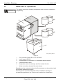
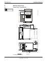
1
Installation Planning Order No.: DD+DIS303.03E Classic E.O.S. *1WACPK1* 1 piece WACPK MA 1 Type 5270/100 Classic E.O.S. CL Type 5270/105 INSTALLATION PLANNING and Technical Data Internal Version 6 R .CD _02 000 0 1 0_ 527 The Installation Planning Instructions can also be ordered separately. Order number: DD+DIS303.03E printed in Germany 02 / 2004 Agfa Group Confidential Caution: This system uses mains voltage. Please observe the pertinent safety instructions. These instructions describe adjustments and routines, which must only be performed by qualified technical personnel. Note: Electrical repairs and connections must only be made by certified electricians. Mechanical repairs and connections must only be made by certified technicians. CE Declaration: According to the medical directives the CE Declaration (CE Conformity) becomes void if the product is modified without permission of the manufacturer! This applies to all parts, not only the safety devices! We reserve the right to change data and characteristics in the light of technical progress. Installation Planning DD+DIS303.03E Chapter 14 Contents 1 Safety............................................................................. 1 2 Scope of Delivery and Accessories ............................ 3 2.1 Classic E.O.S. Type 5270/100..............................................3 2.2 Classic E.O.S. CL Type 5270/105 ........................................3 2.3 Peripheral equipment ...........................................................4 2.4 Exhaust connection through the floor ................................4 3 System Overview.......................................................... 5 3.1 Classic E.O.S. Type 5270/100..............................................5 3.2 Classic E.O.S. CL Type 5270/105 ........................................6 4 Machine Dimensions.................................................... 7 4.1 Classic E.O.S. Type 5270/100..............................................7 4.2 Classic E.O.S. CL Type 5270/105 ........................................8 5 Transport path .............................................................. 9 6 Access for Repair and Maintenance ......................... 10 6.1 Classic E.O.S. Type 5270/100............................................10 6.2 Classic E.O.S. CL Type 5270/105 ......................................11 7 Daylight / Darkroom Installation (only Classic E.O.S. Type 5270/100) ......................... 12 7.1 Machine in the daylight, film feed in the darkroom, light seal at the darkroom feed table.................................12 Installation at the wall opening ..............................................12 Installation with light tight wall ...............................................13 7.1.1 7.1.2 7.2 Edition 6, Revision 0 7.2.1 Machine in the darkroom, film exit in the daylight, light seal at the dryer with light tight wall .........................14 Installation at the wall opening with light tight wall.................14 7.3 Light tight wall ....................................................................15 8 Installation .................................................................. 16 8.1 Hoses and installation material .........................................16 8.2 Supply and disposal through the lower front panel (only Classic E.O.S. Type 5270/100) ..................................17 Classic E.O.S. / Classic E.O.S. CL (Type 5270 / 100 / 105) Chapter 14 / I Installation Planning Chapter 14 / II DD+DIS303.03E 8.2.1 8.2.2 8.2.3 8.2.4 Instructions for breaking out the openings............................ 17 Required openings for standard installations........................ 17 Installing the developer / fixer supply hoses ......................... 18 Installing the disposal hoses ................................................ 19 8.3 8.3.1 Supply and disposal through the floor............................. 20 Installing the disposal hoses ................................................ 21 8.4 Replenisher tanks for developer and fixer ....................... 22 8.5 Disposal tanks.................................................................... 23 8.6 8.6.1 8.6.2 8.6.3 Water connection ............................................................... 24 Wall / machine connection at a water pressure of 2 – 6 bar . 25 Wall / machine connection at a water pressure > 6 bar ........ 26 Overview of adaptation parts for water installations:............. 27 8.7 8.7.1 8.7.2 Exhaust connection ........................................................... 29 Exhaust connection through lower front panel (only Type 5270/100) ........................................................... 29 Exhaust connection through the floor ................................... 30 8.8 Electrical connection of the machine ............................... 31 9 Technical Data .............................................................33 9.1 Electrical data..................................................................... 33 9.2 Ambient and climatic conditions ...................................... 33 9.3 Transport and storage conditions .................................... 34 10 Machine Specifications...............................................35 10.1 Type overview .................................................................... 35 10.2 Film types ........................................................................... 35 10.3 Film formats ....................................................................... 35 10.4 Functional data................................................................... 36 11 Dimensions and Weights............................................37 11.1 Classic E.O.S. Type 5270/100 ........................................... 37 11.2 Classic E.O.S. CL Type 5270/105 ..................................... 37 12 Machine Standards and Directives ............................38 12.1 Safety .................................................................................. 38 12.2 Radio interference suppression........................................ 38 12.3 Electromagnetic compatibility .......................................... 38 12.4 Certificates and guidelines................................................ 39 13 Checklist for Installation Planning.............................41 Classic E.O.S. / Classic E.O.S. CL (Type 5270 / 100 / 105) Edition 6, Revision 0 Installation Planning DD+DIS303.03E 1 Safety General safety instructions • The machine must only be used as described in the operating instructions. Any other use may result in damage to the machine or may affect the machine function with the consequence that the machine can no longer be used as intended, and therefore presents a risk for patients, user, and environment. • The machine must only be operated by qualified personnel trained on the machine. • Ensure that only trained personnel have access to the machine. • Ensure that the machine can always be supervised and that any tampering is prevented. • Repairs or modifications on the machine must only be performed by trained service personnel authorized by Agfa. • In case of visible damage on the machine housing the machine must not be operated or used, and must immediately be disconnected from the mains. • Built-in or external safety devices must not be circumvented or disabled. • Disconnect the machine from the mains before starting any maintenance. • If a mains connection is absolutely required these maintenance routines must only be made by specially trained personnel. • Like all technical devices, this machine must be operated, cared for and serviced correctly as described in the documentation provided with the machine. • If the machine is not operated correctly, or if it is not serviced correctly, Agfa will not be liable for any resulting disturbances, damage or injuries. • When installing the machine make sure that either the mains plug or an all-cable disconnecting device is provided in the internal installation close to the machine and is easily accessible. • If the machine is connected with other components or assemblies, Agfa will guarantee safety only for combinations which are approved by Agfa. • In case of conspicuous smoke or noises, immediately disconnect the machine from the mains. Special instructions for the handling of chemicals • When handling chemicals, always observe the applying safety and environmental regulations, as well as the operating and warning instructions pertaining to these chemicals. • Wear stipulated protective clothing and safety goggles. • When disposing of chemicals and waste water, you must comply with the local regulations concerning waste water and environmental protection. • If photo-chemicals get in your eyes, proceed exactly according to the warning instructions and/or the instructions published by the manufacturers of the chemicals. If required, immediately rinse your eyes with cold water. Afterwards see the doctor immediately. • Avoid inhaling of chemical fumes. Make sure that there is sufficient ventilation at the installation site of the machine, i.e. an air exchange that is at least ten times the room volume per hour. • Always comply with the installation instructions. • Verify tightness of all connections for chemicals and water, as well as waste water, on the machine in regular intervals. At least check whenever suggested in the operating instructions and/or service instructions. Edition 6, Revision 0 Classic E.O.S. / Classic E.O.S. CL (Type 5270 / 100 / 105) Chapter 14 / 1 Installation Planning DD+DIS303.03E • If solution gets into the inside of the machine (e.g. by spilling during tank filling), the machine must immediately be disconnected from the mains and cleaned thoroughly by the service personnel. • Do not use chlorine or chlorine containing substances in the film processor. The use of chlorine or chlorine containing substances may cause irreparable damage in your film processor. Use of these substances may result in termination of the manufacturer’s warranty. The film processor must not be operated in the direct vicinity of the patients as defined in EN60601-1 and IEC 601-1. Adherence to safety regulations • This film processor meets the safety requirements as defined in EN 60950: 1997 (IEC 950) and EN 60601-1-2: 1993, UL 1950 and CSA C22.2 No. 950 and has interference suppression as defined in EN 50081-1, EN 55011, and FCC 47 Part 15, Subchapter B, Class A. • The water connection is in compliance with DIN 1988 / EN 1717:2001. Chapter 14 / 2 Classic E.O.S. / Classic E.O.S. CL (Type 5270 / 100 / 105) Edition 6, Revision 0 Installation Planning DD+DIS303.03E 2 Scope of Delivery and Accessories 2.1 Classic E.O.S. Type 5270/100 Machine Type Power connection Classic E.O.S. 5270/100 1 N~ 230 V (200-240 V) 50/60 Hz ABC Code 37XK3 Accessory box • Wire chute • Exhaust hose including joint to the connection stub • Power cable UL NEMA 6-20 P • Power cable VDE CEE 7 standard cover VII • Sealing tape 12x12mm; 1.3m long; self-adhesive • Pipe • Label (wrap-around) DEV, FIX, WAT; OVERFLOW • Installation kit • Accessory box with small installation parts • Accessory box with installation parts for the exhaust • Technical documentation 2.2 Classic E.O.S. CL Type 5270/105 Machine Type Power connection Classic E.O.S. CL 5270/105 1 N~ 230 V (200-240 V) 50/60 Hz ABC Code EFPHK Accessory box • Wire chute • Exhaust hose including joint to the connection stub • Power cable UL NEMA 6-20 P • Power cable VDE CEE 7 standard cover VII • Sealing tape 12x12mm; 1.3m long; self-adhesive • Pipe • Label (wrap-around) DEV, FIX, WAT; OVERFLOW • Installation kit • Accessory box with small installation parts • Accessory box with installation parts for the exhaust • Technical documentation Edition 6, Revision 0 Classic E.O.S. / Classic E.O.S. CL (Type 5270 / 100 / 105) Chapter 14 / 3 Installation Planning 2.3 2.4 DD+DIS303.03E Peripheral equipment Mixer Type 5280 Mixer communication cable (Mixer to film processor) CM+9528030301 Replenisher tanks (2 x 30 liters) with level sensor / cable 5 m Type 8186 / 701 ABC Code: FJ1QL Replenisher tanks (2 x 80 liters) with level sensor / cable 6 m Type 8186 / 101 ABC Code: F98XW Exhaust connection through the floor Order an additional exhaust stub Ø 100 mm, CM+9522030091 Chapter 14 / 4 Classic E.O.S. / Classic E.O.S. CL (Type 5270 / 100 / 105) Edition 6, Revision 0 Installation Planning DD+DIS303.03E 3 System Overview 3.1 Classic E.O.S. Type 5270/100 TYPE 5270/100 4 1 3 2 5270_10014_006.cdr Figure 1 The system requires the following components which must be considered in the planning: 1 Film processor Classic E.O.S. 5270/100 2 Disposal tanks or connection to a centralized disposal system 3 Chemical solution mixer 4 Replenisher tanks for developer and fixer instead of mixer -- Water connection via water filter (not shown) Depending on the customer’s wishes, the film processor can be combined with the following additional equipment. According to the required configuration further installation planning for corresponding equipment (e.g. mixer) must be taken into consideration. Edition 6, Revision 0 Classic E.O.S. / Classic E.O.S. CL (Type 5270 / 100 / 105) Chapter 14 / 5 Installation Planning 3.2 DD+DIS303.03E Classic E.O.S. CL Type 5270/105 TYPE 5270/105 The system requires the following components which must be considered in the planning: 1 3 2 5 4 5270_10014_005.cdr Figure 2 1 Film processor Classic E.O.S. CL 5270/105 2 Laser Imager LR3300 3 Disposal tanks or connection to a centralized disposal system 4 Chemical solution mixer 5 Replenisher tanks for developer and fixer instead of mixer -- Water connection via water filter (not shown) Depending on the customer’s wishes, the film processor can be combined with the following additional equipment. According to the required configuration further installation planning for corresponding equipment (e.g. mixer) must be taken into consideration. Chapter 14 / 6 Classic E.O.S. / Classic E.O.S. CL (Type 5270 / 100 / 105) Edition 6, Revision 0 Installation Planning DD+DIS303.03E 4 Machine Dimensions 4.1 Classic E.O.S. Type 5270/100 710 (27.95) 5270_10014_003.cdr TYPE 5270/100 1065 (41.93) 615 (24.21) 945 (37.20) 1130 (44.49) 60 (2.36) 210 (8.27) 120 (4.72) 1130 (44.49) 985 (38.78) 760 (29.92) 710 (27.95) 385 (15.16) 540 (21.26) 80 (3.15) 495 (19.49) 30 (1.18) 105 (4.13) 130 (5.12) 470 (18.5) 710 (27.95) 30 (1.18) Figure 3 Dimensions in mm (inch) Edition 6, Revision 0 Classic E.O.S. / Classic E.O.S. CL (Type 5270 / 100 / 105) Chapter 14 / 7 Installation Planning 4.2 DD+DIS303.03E Classic E.O.S. CL Type 5270/105 710 (27.95) TYPE 5270/105 1165 (45.87) 1020 (40.16) 795 (31.3) 745 (29.3) 420 (16.54) 540 (21.26) 650 (25.59) 1165 (45.87) 985 (38.81) 740 (29.13) 210 (8.27) 35 (1.38) 65 (2.56) 740 (29.156) LR3300 710 (27.95) 740 (29.156) 470 (18.5) 120 (4.72) 1760 (69.344) 35 (1.38) 5270_10014_004.cdr Figure 4 Dimensions in mm (inch) Chapter 14 / 8 Classic E.O.S. / Classic E.O.S. CL (Type 5270 / 100 / 105) Edition 6, Revision 0 Installation Planning DD+DIS303.03E 5 Transport path The film processor must fit through all doors and hallways on its transport path to the installation site. Classic E.O.S. / Classic E.O.S. CL Smallest door width (Type 5270/100/105) Edition 6, Revision 0 without pallet at least 73 cm (29 inch) with pallet at least 82 cm (32 inch) Classic E.O.S. / Classic E.O.S. CL (Type 5270 / 100 / 105) Chapter 14 / 9 Installation Planning DD+DIS303.03E 6 Access for Repair and Maintenance 6.1 Classic E.O.S. Type 5270/100 TYPE 5270/100 The required floor space for the film processor (with feed table, chute and the required clearance on the left) is 1270 x 860 mm (50.03 x 33.88 inch). The free space indicated in the illustration must be guaranteed for repair and maintenance, otherwise the time required for service will increase. Optimum dimensions: We recommend to plan on this free space. 2340 (92.19) Minimum dimensions: Do not go below this minimum space. 310 (12.21) 5270_10001_004.cdr A Figure 5 (A) Operation side Dimensions in mm (inch) Chapter 14 / 10 Classic E.O.S. / Classic E.O.S. CL (Type 5270 / 100 / 105) Edition 6, Revision 0 Installation Planning DD+DIS303.03E 6.2 Classic E.O.S. CL Type 5270/105 TYPE 5270/105 The required floor space for the film processor in combination with the Laser Imager LR3300, feed table, chute and the required clearance on the left is 1700 x 860 mm (66.98 x 33.88 inch). In case of an installation of the Laser Imager LR3300 or another daylight system observe the installation documentation enclosed with the machine. The free space indicated in the illustration must be guaranteed for repair and maintenance, otherwise the time required for service will increase. Optimum dimensions: We recommend to plan on this free space. Minimum dimensions: Do not go below this minimum space. 2710 (106.77) 1910 (75.25) 1710 (67.37) 860 (33.88) 400 (15.76) 740 (29.15) 600 (23.64) 600 (23.64) A 740 (29.15) 1700 (66.98) 40 (1.57) 2120 (83.52) 3120 (122.92) 380 (14.97) 400 (15.76) LR3300 1000 (39.4) 5270_10001_005.cdr A 300 (11.82) 700 (27.58) 600 (23.64) Figure 6 (A) Operation side Dimensions in mm (inch) Edition 6, Revision 0 Classic E.O.S. / Classic E.O.S. CL (Type 5270 / 100 / 105) Chapter 14 / 11 Installation Planning 7 DD+DIS303.03E Daylight / Darkroom Installation (only Classic E.O.S. Type 5270/100) Chapter 7 “Daylight / Darkroom Installation” only refers to the Standalone Version Type 5270/100. Type 5270/105 has been designed for installation as daylight system. 7.1 Machine in the daylight, film feed in the darkroom, light seal at the darkroom feed table 7.1.1 Installation at the wall opening Film feed Darkroom Film output (wire chute) A 60° chamfer must be provided on the wall opening. Wall Wall base 6 3 1 2 5 527214nm.cdr 50 (1.97) Light seal (foam rubber – by the meter) Order no. CM+0000014259 Daylight 4 min. 1120 (44.1) TYPE 5270/100 Figure 7 Dimensions in mm (inch) Wall opening: min. 580 (22.8) max. 680 (26.8) Wall base Wall opening max. 1120 (44.1) Wall 3 1 2 50 (1.97) 527014jm.cdr Figure 8 Dimensions in mm (inch) Chapter 14 / 12 Classic E.O.S. / Classic E.O.S. CL (Type 5270 / 100 / 105) Edition 6, Revision 0 Installation Planning DD+DIS303.03E Installation with light tight wall TYPE 5270/100 Film feed A 60° chamfer must be provided on the wall opening. Wall Light tight wall Film output (wire chute) Wall base Light seal (foam rubber – by the meter) Order no. CM+0000014259 Darkroom Daylight 3 2 4 1 min. 1120 (44.1) max. 1500 (59.1) 7.1.2 5 7 6 527014pm.cdr Figure 9 Dimensions in mm (inch) Wall opening 3 2 1 2 50 (1.97) Wooden board, 20 mm (0.79 inch) with opening min. 1110 (43.7) max. 1120 (44.1) Overlap wall / light tight wall at least 5 cm on all sides 1550 (61.0) Wall 1 min. 670 (26.4) max. 680 (26.8) 527014lm.cdr Figure 10 Dimensions in mm (inch) See 7.3, Light tight wall Edition 6, Revision 0 Classic E.O.S. / Classic E.O.S. CL (Type 5270 / 100 / 105) Chapter 14 / 13 Installation Planning DD+DIS303.03E 7.2 Machine in the darkroom, film exit in the daylight, light seal at the dryer with light tight wall 7.2.1 Installation at the wall opening with light tight wall Darkroom 1 Film feed 2 3 Wall A 60° chamfer must be provided on the wall opening. 4 5 6 Light tight wall Film output (wire chute) Light seal (foam rubber – by the meter) Order no. CM+0000014259 Wall base 7 Daylight 2 3 1 min. 1120 (44.1) max. 1500 (59.1) TYPE 5270/100 6 7 527014rm.cdr Figure 11 Dimensions in mm (inch) The lower the height of the wall opening the more difficult will be the access to the film removal. Wall opening Wall 2 Overlap wall / light tight wall at least 50 mm (1.97 inch) on all sides 2 2 50 (1.97) 3 Wooden board, 20 mm (0.79 inch) with opening min. 1110 (43.7) max. 1120 (44.1) 1 1550 (61.0) 3 1 1 min. 670 (26.4) max. 680 (26.8) 527014lm.cdr Figure 12 Dimensions in mm (inch) See 7.3, Light tight wall Chapter 14 / 14 Classic E.O.S. / Classic E.O.S. CL (Type 5270 / 100 / 105) Edition 6, Revision 0 Installation Planning DD+DIS303.03E Light tight wall 5273_10003_004.cdr 7.3 min. 1110 (43.7) max. 1120 (44.1) TYPE 5270/100 min. 670 (26.4) max. 680 (26.8) 1020 (40.2) Figure 13 Dimensions in mm (inch) Coverage of a wall opening of up to 1400 mm x 900 mm (55.16 inch x 35.46 inch) is possible. An overlap of 50 mm (1.97 inch) must be guaranteed on all sides. The manufacturer does not supply the light tight wall (wooden board) required for the installation of a film processor! Edition 6, Revision 0 Classic E.O.S. / Classic E.O.S. CL (Type 5270 / 100 / 105) Chapter 14 / 15 Installation Planning DD+DIS303.03E 8 Installation 8.1 Hoses and installation material Only use fiber-reinforced PVC hoses Ø 19x4 mm for the external hose connections (outside the machine)! The supply and disposal hoses for developer, fixer, water, and safety overflow in the machine are marked by tapes: DEV WAT = developer = water FIX OVERFLOW = fixer = safety overflow Tapes to be wrapped around external hoses are included in the accessory box. The following hoses are to be used for the supply connections: Supply Color Dimensions Order number connection (mm / inch) Developer red (DEV) 10x3 / 0.39x0.12 CM+0000064082 fiber-reinforced Fixer blue (FIX) 10x3 / 0.39x0.12 CM+0000064083 fiber-reinforced The following hoses are to be used for the disposal connections: Disposal Color Dimensions Order number connection (mm / inch) Developer red (DEV) 19x4 / 0.75x0.16 CM+0000064133 fiber-reinforced Fixer blue (FIX) 19x4 / 0.75x0.16 CM+0000064134 fiber-reinforced Water transparent 19x4 / 0.75x0.16 CM+0000007620 safety overflow (WAT) fiber-reinforced The accessory box includes an approx. 50 cm (19.69 inch) long PAP hose for the exhaust connection. The PAP hose (Ø 100 mm / Ø 3.94 inch) can be ordered by the meter: Order number CM+0000064117 Hose clamp Supply CM+9037170090 Disposal CM+9037200400 Exhaust CM+7037196490 Hose connection Disposal Chapter 14 / 16 Supply CM+9521075161 CM+9521075041 Threaded bush CM+9521075050 Y – connector CM+9034200440 Exhaust connection ∅ 100 mm (3.93 inch) Order an additional joint for the floor connection! CM+9522030091 Classic E.O.S. / Classic E.O.S. CL (Type 5270 / 100 / 105) Edition 6, Revision 0 Installation Planning DD+DIS303.03E 8.2 Supply and disposal through the lower front panel (only Classic E.O.S. Type 5270/100) 8.2.1 Instructions for breaking out the openings TYPE 5270/100 8.2.2 • It is not necessary to remove the front panel in order to break out the openings. • Mark the recesses to be broken out with a felt-tip marker. • The material can be broken out by holding a screwdriver against he groove and hitting it with a hammer. 527303nm.cdr Figure 14 Required openings for standard installations TYPE 5270/100 (A) Exhaust connection (B) Developer overflow / drain (C) Fixer overflow / drain 1 (D) Water overflow / drain E (E) Safety overflow, tanks D (F) Developer supply C F (G) Fixer 2 supply B G (H) Water supply A H 5273_10002_004.cdr Figure 15 Edition 6, Revision 0 Classic E.O.S. / Classic E.O.S. CL (Type 5270 / 100 / 105) Chapter 14 / 17 Installation Planning 8.2.3 DD+DIS303.03E Installing the developer / fixer supply hoses TYPE 5270/100 Only use fiber-reinforced PVC hoses Ø 10x3 mm (0.39x0.12 inch) for the external hose connections (outside the machine)! Position the hoses without kinks! Installing the developer / fixer supply: 2 1 3 4 5 7 8 6 G 7 10 F 9 A 527003OM.CDR Figure 16 (F) (G) POS 1 2 3 4 5 6 7 8 9 10 Chapter 14 / 18 Developer (DEV) Fixer (FIX) (A) Supply direction Designation PVC hose Ø 9x1.5 mm (0.35x0.06 inch) Hose positioning / reinforcement bend-protection Hose clamp Hose connection stub Threaded bush Rubber elbow Ø 10 mm (0.39 inch) Hose clamp Pipe stub Ø 10x1 mm (0.39x0.04 inch) PVC hose Ø 10x3 mm (0.39x0.12 inch) fiber-reinforced Developer: red Fixer: blue Hose clamp Configuration Pre-installed in the machine Not included in shipment, can be ordered, CM+7946064580 Pre-installed in the machine Included in the accessory box Not included in shipment, can be ordered, CM+9511017970 Not included in shipment, can be ordered, CM+7037200210 Not included in shipment, can be ordered, CM+9511017920 Not included in the shipment, can be ordered, CM+0000064082 CM+0000064083 Not included in shipment, can be ordered, CM+7037200230 Classic E.O.S. / Classic E.O.S. CL (Type 5270 / 100 / 105) Edition 6, Revision 0 Installation Planning DD+DIS303.03E 8.2.4 Installing the disposal hoses TYPE 5270/100 Only use fiber-reinforced PVC hoses Ø 19x4 mm (0.75x0.16 inch) for the external hose connections (outside the machine)! Position the hoses without kinks! A 1 2 3 4 6 5 5 7 5 B 8 D E 527003QM.CDR Figure 17 (A) (B) (C) Drain direction Developer drain / overflow Fixer drain / overflow (D) (E) Pos Designation 1 PVC hose Ø 19x2.5 mm (0.75x0.10 inch) transparent 2 Hose clamp 3 Hose connection stub Ø 20 mm (0.79 inch) 4 Threaded bush 5 Hose clamp 6 Rubber elbow 7 Water drain / overflow Safety overflow, tanks Configuration Pre-installed in the machine Included in the accessory box Not included in shipment, can be ordered, CM+9037200400 Not included in shipment, can be ordered, CM+9889629521 Not included in shipment, can be ordered, CM+7839185010 Not included in shipment, can be ordered CM+0000064133 Pipe stub Ø 20 mm (0.79 inch) 8 PVC hose, Developer (red, fiber-reinforced): Ø 19x4 mm (0.75x0.16 inch) Fixer (blue, fiber-reinforced): Ø 19x4 mm (0.75x0.16 inch) CM+0000064134 Water (transparent, fiber-reinforced): Ø 19x4 mm (0.75x0.16 inch) CM+0000007620 • Combine the hoses of the safety overflow (OVERFLOW) and water (WAT) with a Y piece and connect them with one drain hose, if this is permitted by the local regulations. Install the drain hose to the floor drain. Edition 6, Revision 0 Classic E.O.S. / Classic E.O.S. CL (Type 5270 / 100 / 105) Chapter 14 / 19 Installation Planning 8.3 DD+DIS303.03E Supply and disposal through the floor Only use fiber-reinforced PVC hoses Ø 10x3 mm (0.39x0.12 inch) for the external hose connections (outside the machine)! Position the hoses without kinks! Classic E.O.S. CL (5270/105) Classic E.O.S. (5270/100) TYPE 5270/105 TYPE 5270/100 H 1 3 4 9 1 H 4 10 9 1 3 5270_10003_016.CDR 4 5270_10014_011.CDR 10 9 Figure 19 Figure 18 Pos Designation 1 PVC hose Ø 9x1.5 mm (0.35x0.06 inch) 3 Hose clamp 4 Hose connection stub 10 Hose clamp 9 H PVC hose Ø 10x3 mm (0.39x0.12 inch) fiber-reinforced Developer: red Fixer: blue Safety pressure hose Configuration Pre-installed in the machine Not included in shipment, can be ordered, CM+7037200230 Not included in the shipment, can be ordered, CM+0000064082 CM+0000064083 Included in the accessory box • If necessary shorten the internal supply hoses and insert the hose connection stub (4) again. • Connect the fiber-reinforced (external) PVC hoses with the hose connection stub (4) of the internal supply hoses. • Position the hoses together through the opening in the bottom to the mixer or to the individual tanks. Chapter 14 / 20 Classic E.O.S. / Classic E.O.S. CL (Type 5270 / 100 / 105) Edition 6, Revision 0 Installation Planning DD+DIS303.03E 8.3.1 Installing the disposal hoses WAT FIX2 FIX1 DEV 1 2 3 5 8 5270_10003_017.CDR Figure 20 Pos Designation 1 PVC hose Ø 19x2.5 mm (0.75x0.10 inch) transparent 2 Hose clamp 3 Hose connection stub Ø 20 mm (0.79 inch) 5 Hose clamp 8 PVC hose, Developer (red, fiber-reinforced): Ø 19x4 mm (0.75x0.16 inch) Fixer (blue, fiber-reinforced): Ø 19x4 mm (0.75x0.16 inch) Water (transparent, fiber-reinforced): Ø 19x4 mm (0.75x0.16 inch) Configuration Pre-installed in the machine Not included in the shipment, CM+9037200400 Not included in shipment, can be ordered CM+0000064133 CM+0000064134 CM+0000007620 • Shorten the internal disposal hoses if necessary and insert the hose connection stub (3) again. • Connect the fiber-reinforced (external) PVC hoses with the hose connection stub (3) of the internal disposal hoses. • Position the disposal hoses of developer (DEV) and fixer (FIX) together through the opening in the bottom and to the central disposal site. • Combine the hoses of the safety overflow (OVERFLOW) and water (WAT) with a Y piece and connect them with one drain hose, if this is permitted by the local regulations. Install the drain hose to the floor drain. Edition 6, Revision 0 Classic E.O.S. / Classic E.O.S. CL (Type 5270 / 100 / 105) Chapter 14 / 21 Installation Planning 8.4 DD+DIS303.03E Replenisher tanks for developer and fixer Replenisher pump with filter Replenisher tanks or Mixer Replenisher hose Figure 21 • To be observed for the use of individual tanks or a mixer: maximum suction height: 2 m (78.74 inch) maximum suction length: 15 m (590.55 inch) Replenisher tanks must not be installed inside the machine! The customer cannot refill the tanks! Level monitoring in the replenisher tanks Four plugs are provided on the Control Board PCB1 for connection of the replenisher supply for mixer, developer, fixer, and for the anti-algae solution. A communication cable with 20 m (787.4 inch) an be ordered for the Mixer: CM+9528030301 Chapter 14 / 22 Classic E.O.S. / Classic E.O.S. CL (Type 5270 / 100 / 105) Edition 6, Revision 0 Installation Planning DD+DIS303.03E 8.5 Disposal tanks For disposal of chemicals and wash water the regulations of the local authorities regarding the pertaining Sewage Act must be observed! If it is allowed to drain the exhausted solutions into the sewer, then the drain pipe must be a polyethylene pipe up to the main pipe (vertical drain pipe). The installation of the disposal lines to the disposal tanks must be carried out professionally by authorized technicians. In Germany this must be done in compliance with §19 WHG and DIN 1988 / EN 1717:2001. In other countries the corresponding national regulations must be considered. It must be guaranteed that developer or fixer solution never gets into the wash water, not even in case of overflow due to clogged lines, if the wash water is drained into the public sewage system. Install the respective hoses and protection facilities. In Germany the pertaining regulations are the general minimum requirements for the disposal of waste water in waters, dated Jan. 31, 1994, Appendix 53 – Photographic Processes (silver halide photography). In other countries the respective country-specific regulations and laws must be observed. Disposal possibilities Disposal through the front panel (only type 5273/100): Disposal connections through the lower front panel: • Disposal in individual tanks (developer / fixer), and water is drained in the sewer, or • Disposal in centralized disposal station Disposal connections through the lower front panel Disposal tanks Figure 22 In case of a disposal with individual tanks, the disposal hoses are always filled with chemicals. Disposal through the floor: Disposal through the floor to the centralized disposal station with one disposal hose each for developer, fixer, and water. For maintenance purposes we recommend a separate drain fro cleaning chemicals. Centralized disposal Drain hoses (below the film processor) Edition 6, Revision 0 Classic E.O.S. / Classic E.O.S. CL (Type 5270 / 100 / 105) Figure 23 Chapter 14 / 23 Installation Planning 8.6 DD+DIS303.03E Water connection Also see Chapter 3 Water consumption Permanent replenishment: max. 3 liters / min (101.45 fl.oz. / min). The water supply rate per square meter of processed film can be changed via code. Water pressure 2 bar (200 kPa) to 6 bar (600 kPa) Water temperature pH value min. 5 °C 6.5 to 8 Water conductivity value min. 3µS/cm Reliable level detection in the water tank cannot be guaranteed if this value is too low. Regulations The free water supply of the machine is in compliance with the regulations of DIN 1988 / EN 1717:2001 (technical regulations for the installation of drinking water). - Shut-off valve not included in shipment Clutch 1 2 3 4 Threaded fitting 5 6 230 7 2000 (78.7) Pressure reducer (manometer), for water pressure > 6 bar Flexible safety pressure hose Solenoid valve Dirt filter 527314sm.cdr Dimensions in mm (inch) Figure 24 • Position the safety pressure hose, mounted at the dirt filter, all the way to the shut-off valve or pressure reducer. Safety CM+9036260160 pressure hose: tested in compliance with DIN 57700 Part 600 2 m (78.74 inch) long ³/4" union nut • For safety we recommend to provide a floor drain close to the machine. Chapter 14 / 24 Classic E.O.S. / Classic E.O.S. CL (Type 5270 / 100 / 105) Edition 6, Revision 0 Installation Planning DD+DIS303.03E 8.6.1 Wall / machine connection at a water pressure of 2 – 6 bar To protect the drinking water from a return flow of waste water via the hand shower a safety fitting (1) must be installed. This consists of a ventilation valve with integrated check valve. The installation according to the standard DIN 1988 / EN 1717:2001 must follow the illustration! 3/4" (1/2)" (3/4)" USA 1/2" 4 1 3 2 min. 150 mm X Y Z 527214VM.CDR Figure 25 If necessary the individual assemblies must X be supported. Y Z Pos. Edition 6, Revision 0 1 Part number FU+8966008 Qty 1 2 FU+58618 1 3 CM+9034200580 1 4 CM+9034200590 1 Cleaning sink Overflow Waste water Designation Size Safety combination, ½" chromium plated Hand shower with ½" hose Hexagon reduction ¾" USA piece (brass) Hexagon reduction ¾" piece (brass) Classic E.O.S. / Classic E.O.S. CL (Type 5270 / 100 / 105) Remarks optional Chapter 14 / 25 Installation Planning 8.6.2 DD+DIS303.03E Wall / machine connection at a water pressure > 6 bar To protect the drinking water from a return flow of waste water via the hand shower a safety fitting (1) must be installed. This consists of a ventilation valve with integrated check valve. The installation according to the standard DIN 1988 / EN 1717:2001 must follow the illustration! Set the pressure reducer to a pressure value between 2 and 6 bar! 3/4" (1/2)" (3/4)" USA 1/2" 1/2" 1 3 2 4 min. 150mm 5 X Y Z 527214WM.CDR Figure 26 If necessary the individual assemblies must X be supported. Y Z Pos. Chapter 14 / 26 1 Part number FU+8966008 Qty 1 2 FU+58618 1 3 FU+8656001 1 4 FU+8656002 1 5 CM+9034200590 1 Designation Safety combination, chromium plated Hand shower with hose Pressure reducer SYR 315 Manometer 0 - 10 bar Hexagon reduction piece (brass) Classic E.O.S. / Classic E.O.S. CL (Type 5270 / 100 / 105) Cleaning sink Overflow Waste water Dimensions ½" Remarks ½" ½" optional ½" ¾" Edition 6, Revision 0 Installation Planning DD+DIS303.03E 8.6.3 Overview of adaptation parts for water installations: Adaptation part with name Connection Order number/ part number A ½ " external thread B ¾ " external thread CM+7034200320 Reduction nipple (brass) A ¾ " external thread CM+9034200600 B ¾ " external thread Double nipple (brass) A ½ " external thread B ½ " external thread CM+7034200260 Double nipple (brass, chromium plated) A ¾ " internal thread + seal B ½ " external thread CM+7034215230 Reduction piece with seal (movable parts; brass, chromium plated) A ½ " internal thread B ¾ " external thread CM+7034200280 Reduction nipple (brass) A ¾ " external thread B ½ " internal thread CM+9034200590 Reduction piece (brass) Edition 6, Revision 0 Classic E.O.S. / Classic E.O.S. CL (Type 5270 / 100 / 105) Chapter 14 / 27 Installation Planning DD+DIS303.03E Adaptation part with name Connection Order number/ part number A ¾ " external thread CM+9034200580 Reduction piece (fitting for USA) B 1.085-12 UNS-3B internal thread PIPE THREADS American National Standard A ¾ " external thread CM+7512017410 (GHT) PIPE THREADS American National Standard B ½ " internal thread Fitting for USA (water connection humidifier) A ¾ " internal thread B ½ " external thread CM+7523010550 Reduction piece (brass, compact part) for ½ " screw connection CM+9896611740 ¾ " screw connection CM+9034200610 Flat seal A ¾" union nut B ¾" union nut Pressure hose Chapter 14 / 28 Classic E.O.S. / Classic E.O.S. CL (Type 5270 / 100 / 105) CM+9036260160 Edition 6, Revision 0 Installation Planning DD+DIS303.03E 8.7 Exhaust connection Also see Chapter 3, Section 6 8.7.1 Exhaust connection through lower front panel (only Type 5270/100) Flexible exhaust hose ∅ 100 mm Crossover Connection piece for exhaust hose Dimensions in mm Figure 27 The film processor has an integrated exhaust unit. • Connection stub at the machine: ∅ 100 mm • Max. length of the exhaust hose: 5 m. If the hose is longer install an additional fan! • Exhaust volume: min. 50 m³/h – max. 100 m³/h For functional reasons the exhaust connection must always lead out of the machine. Edition 6, Revision 0 Classic E.O.S. / Classic E.O.S. CL (Type 5270 / 100 / 105) Chapter 14 / 29 Installation Planning 8.7.2 DD+DIS303.03E Exhaust connection through the floor Dimensions in mm Flexible exhaust hose ∅ 100 mm Exhaust connection through the floor Exhaust connection: 2 screw-type exhaust connections; center hole through the floor _ 114 mm ∅> Order no.: CM+9522030091 Figure 28 The film processor has an integrated exhaust unit. • Connection stub at the machine: ∅ 100 mm • Max. length of the exhaust hose: 5 m If the hose is longer install an additional fan! • Exhaust volume: min. 50 m³/h – max. 100 m³/h For functional reasons the exhaust connection must always lead out of the machine. Chapter 14 / 30 Classic E.O.S. / Classic E.O.S. CL (Type 5270 / 100 / 105) Edition 6, Revision 0 Installation Planning DD+DIS303.03E 8.8 Electrical connection of the machine Power connection 1N~ 230 – 240 V; 50/60 Hz (200 - 240 V) Fuse protection 15 / 16 A A GFI switch: (IN = 30 mA in compliance with VDE 664) is integrated in the machine. Leakage current towards PE Protective earth < 3.5 mA Installation regulations VDE Electrical installations in the installation room must be in compliance with the regulations IEC 364, VDE 0100 and VDE 0107. < 0.1 Ω towards ground UL Mains connection in the installation room VDE Double shockproof outlet according to DIN 49441 and CEE 7 standard plate VII UL Required connection cable (scope of delivery) Edition 6, Revision 0 Outlet for three-prong plugs NEMA 6-20 R VDE PVC line H05VV - F 3G 1.5 (3 wires) cable length 3.5 m usable length 2.3 m UL Main breaker Electrical installations in the installation room must be in compliance with the regulation "National Electrical Code" (NEC) (NFPA 70). Cable included in the accessory box to replace the VDE cable. PVC line SJT 3 x AWG 12 (with plug NEMA 6-20 P) cable length 3.4 m usable length 2.4 m Upon machine installation it must be ensured that either the mains connector or an all-pole circuit breaker for the installation on site is located close to the machine and easily accessible. Classic E.O.S. / Classic E.O.S. CL (Type 5270 / 100 / 105) Chapter 14 / 31 Installation Planning DD+DIS303.03E Outlet connection: All-pole main breaker (option: if there is no access to the outlet) Mains supply with outlet Power cable with three-prong plug GFI switch (IN = 30 mA, in compliance with VDE 664) Note: Parts and are not included in the machine shipment. 1 4 2 3 527314km.cdr Figure 29 Chapter 14 / 32 Classic E.O.S. / Classic E.O.S. CL (Type 5270 / 100 / 105) Edition 6, Revision 0 Installation Planning DD+DIS303.03E 9 Technical Data 9.1 Electrical data Power connection 1N~ 230 – 240 V; 50/60 Hz (200 - 240 V) Power consumption: Standby (room temperature ~ 20 °C) during film processing 0.45 kWh (1620 kJ) Fuse protection 15 A / 16 A Leakage current towards PE < 3.5 mA Main breaker Safety regulations 2.9 kW/h (10440 kJ/h) Upon machine installation it must be ensured that either the mains connector or an all-pole circuit breaker for the installation on site is located close to the machine and easily accessible. Electrical installations in the installation room must be incompliance with IEC 364 (VDE 0100 / 0107). A GFI switch: (IN = 30 mA in compliance with VDE 664) is integrated in the machine. 9.2 Ambient and climatic conditions Room temperature min. 10 °C (50 °F), max. 30 °C (86 °F) Room temperature min. 5 °C (41 °F) below the set developer temperature Relative humidity min. 10 %, max. 80 %, no condensation Ventilation Avoid inhaling of chemical fumes. Make sure that there is sufficient ventilation at the installation site of the machine, i.e. an air exchange that is at least ten times the room volume per hour. Light-tightness maximum 2500 Lux The machine must not be opened during the operation. It is light tight only if all panels are correctly mounted. Acoustic test ISO 7779 (airborne noise) Edition 6, Revision 0 during standby during film cycle Classic E.O.S. / Classic E.O.S. CL (Type 5270 / 100 / 105) max. 35 dB (A) max. 48 dB (A) Chapter 14 / 33 Installation Planning DD+DIS303.03E Radiation effects Upon machine installation in the close vicinity to the X-ray room, the local regulations for radiation protection must be followed (protection of personnel against scattered radiation). The machine has not been designed for the installation in the X-ray room, i.e. there is no internal screening against scattered radiation. Floor conditions Waterproof, chemical-resistant floor covering (pH value 4 - 11) A floor drain close to the film processor is recommended. Floor load 50 N / cm² (7.75 N / in²) Cleaning sink A cleaning sink with water tap and hose shower should be provided for maintenance work. Minimum inside dimensions of the sink: Heat emission (approx. values) Width Depth Height Standby (max.) Film run (max.) Exhaust connect. 9.3 70 cm (27.56 inch) 40 cm (15.75 inch) 20 cm (7.87 inch) into the room 250 W / 900 kJ/h into the connected 1200 W / 4320 kJ/h exhaust into the room 900 W / 3240 kJ/h total 2100 W / 7560 kJ/h Integrated exhaust in the dryer is a standard feature. During film cycle the exhaust runs at full capacity. During standby mode the exhaust can be set to half-capacity via the service program. Transport and storage conditions Ambient temperature up to max. -25 °C for 72 h max. 55 °C for 96 h (IEC 68-2-1 (Ab)) (IEC 68-2-2 (Bb)) Relative humidity in the given temperature range between 5% and 95%. Chapter 14 / 34 Classic E.O.S. / Classic E.O.S. CL (Type 5270 / 100 / 105) Edition 6, Revision 0 Installation Planning DD+DIS303.03E 10 Machine Specifications 10.1 Type overview Machine Type Classic E.O.S. 5270/100 1N~ 230-240 V (200 - 240 V) 50/60 Hz 5270/105 1N~ 230-240 V (200 - 240 V) 50/60 Hz Classic E.O.S. CL 10.2 Power connection ABC Code ECZ26 ECZ38 Film types All commercially available medical x-ray films suitable for machine processing. 10.3 Film formats Type 5270/100 Sheet films Roll film Edition 6, Revision 0 10 x 10 cm (3.9 x 3.9 inch) 35 x 43 cm (13.8 x 16.9 inch) 43.5 cm (17.1 inch) Processing of roll film is NOT possible! Type 5273/105 Sheet films Roll film smallest size largest size max. film width smallest size largest size max. film width 13 x 18 cm (5.1 x 7.1 inch) 35 x 43 cm (13.8 x 16.9 inch) 43.5 cm (17.1 inch) Processing of roll film is NOT possible! Classic E.O.S. / Classic E.O.S. CL (Type 5270 / 100 / 105) Chapter 14 / 35 Installation Planning 10.4 DD+DIS303.03E Functional data Process code Feeding speed Processing time in DEV Processing time (film 35 x 35 cm) Film: end / end incl. Film Films / h (35 x 35 cm) Machine tank volumes Developer Fixer 1 Fixer 2 Water Developer tank temperature standard adjustable between 25 °C (77 °F) - 39 °C (102.2 °F) Fixer 2 tank temperature Heating time from 20 °C (68 °F) to 34 °C (93.2 °F) Dryer step setting Standard setting replenishment cycles Developer / fixer Standard setting Replenishment rate Developer / fixer Water Range Replenishment rate Developer / fixer Water Water supply Adjustment range for water pressure min. max. Water conductivity value Water pH value Silver concentration in the waste water Chapter 14 / 36 HT (60s) 160 cm/min (62.99 in/min) 12.5 sec IP (90s) 106 cm/min (41.73 in/min) 18.8 sec RP (2min) 80 cm/min (31.5 in/min) 24.9 sec EXT (3min) 52 cm/min (20.47 in/min) 38.3 sec 71 sec 82 sec 107 sec 124 sec 142 sec 164 sec 218 sec 253 sec 220 150 110 75 34 °C (93.2 °F) 34 °C (93.2 °F) 8.8 l (297.6 fl.oz.) 10 l (338.18 fl.oz.) 5.8 l (196.15 fl.oz.) 5.8 l (196.15 fl.oz.) 38 °C (100.4 °F) 36 °C (96.8 °F) 34 °C (93.2 °F) approx. 20 min 13 (Software Version CLLC1107; older versions: 10 steps) 0.25 m² (3.88 in²) 400 ml/m² 30000 ml/m² 50 – 800 ml/m² 3000 – 30000 ml/m² 3000 ml/min (101.45 fl.oz./min) 2 bar 6 bar min. 3 µS / cm If the value drops below this threshold reliable level detection in the water tank can no longer be guaranteed! 6.5 to 8 < 1 ppm Classic E.O.S. / Classic E.O.S. CL (Type 5270 / 100 / 105) Edition 6, Revision 0 Installation Planning DD+DIS303.03E 11 Dimensions and Weights 11.1 Classic E.O.S. Type 5270/100 Dimensions Length mm (inch) incl. packing box 1200 (47.24) without packing 1270 (50) material (with feed table and chute) Width mm (inch) 800 (31.5) 710 (27.95) Height mm (inch) 1460 (57.48) 1130 (44.49) Weight with packing material without packing material with full tanks 11.2 Weight approx. kg (lbs) 200 (441) 135 (297) 165 (364) Classic E.O.S. CL Type 5270/105 Dimensions Length mm (inch) incl. packing box 1200 (47.24) without packing 1070 (42.16) material (with docking unit and chute) Width mm (inch) 800 (31.5) 710 (27.95) Height mm (inch) 1460 (57.48) 1130 (44.49) Weight with packing material without packing material with full tanks Edition 6, Revision 0 Weight approx. kg (lbs) 200 (441) 135 (297) 165 (364) Classic E.O.S. / Classic E.O.S. CL (Type 5270 / 100 / 105) Chapter 14 / 37 Installation Planning DD+DIS303.03E 12 Machine Standards and Directives 12.1 Safety Europe EN 60950 / A11 1997 "Safety of Information Technology Equipment" (identical with IEC 950: 1992 and with VDE 0805/ 11. 97). USA UL 1950 July 3, 1995 “Safety of Information Technology Equipment, Including Electrical Business Equipment”. Canada CSA 22.2 No. 950 - 95 “Safety of Information Technology Equipment, Including Electrical Business Equipment”. 12.2 Radio interference suppression Europe In compliance with EN 50081-1: 1992 "Generic Standard for Emission Requirements", (identical with VDE 0839, Part 81-1/ 03. 93) EN 55011 1998, Class B "Radio Disturbance Characteristics of Medical Equipment" (corresponds to VDE 0878, Part 22 / 04.98) For equipment in residential areas, business and commercial areas, and in doctors’ offices. North-America (USA, Canada) US Standard FCC 47 Part 15, Subchapter B, Class A / Edition 8/ 1976 Equipment considered “Non-Household Appliances” 12.3 Electromagnetic compatibility EMVG (German Electromagnetic Compatibility Act) and EC Regulation 89 / 336 / EEC; EN 50082-1: 1997 EN 61000-3-2 “Limit Values for Harmonic Emissions” EN 61000-3-3 “Limit Values for Flicker” Chapter 14 / 38 Classic E.O.S. / Classic E.O.S. CL (Type 5270 / 100 / 105) Edition 6, Revision 0 Installation Planning DD+DIS303.03E 12.4 Certificates and guidelines CE Medical Device Directive 93/42 EEC TÜV Product Service Mark “Design tested and monitored” UL Approbation E 477 50 (M) C-UL Approbation E 477 50 (M) “Technical directives for drinking water installations, protection against reflux” DIN 1988, Part 4/ 1988 / EN 1717:2001 General conditions and Appendix 53 – Photographic Processes administrative regulations for (silver halide photography) minimum requirements on the disposal of waste water into public waters, dated 31.01.1994 (Germany) Ministry for Environmental Rubrique No. 2950 Protection Maximum water consumption for (France) - single-layer emulsions must not exceed a maximum of 15l/m2 * - double-sided emulsions must not exceed a maximum of 30l/m2 * * Activated in the program <Service Settings / Replenishment / Wat. Repl. Value> Edition 6, Revision 0 Classic E.O.S. / Classic E.O.S. CL (Type 5270 / 100 / 105) Chapter 14 / 39 Installation Planning Chapter 14 / 40 DD+DIS303.03E Classic E.O.S. / Classic E.O.S. CL (Type 5270 / 100 / 105) Edition 6, Revision 0 Installation Planning DD+DIS303.03E 13 Checklist for Installation Planning General System components 1 yes no Film processor Daylight system Mixer Replenisher tanks Centralized disposal Disposal tanks Silver recovery (fixer, water) 2 Transport path Sufficient floor load Elevator (door size, load) Door size 3 Installation version Daylight Darkroom 4 Unloading and unpacking Free space provided for lifting the machines off the pallet prepared: yes no Required external connections: 5 Film processor All-pole circuit breaker Outlet (distance to machine:_____m) 6 Mixer Outlet (distance to machine:_____m) 6 Silver recovery Outlet (distance to machine:_____m) 7 Hose connections Supply and disposal through rear wall Supply and disposal through the floor Exhaust hose required, length_____m Exhaust: connection piece installed on site Supply hoses installed Disposal hoses installed 8 Air conditioning system Exhaust connection installed Exhaust rate sufficient 9 Water connection present 10 Free space around machine Required minimum guaranteed 11 Wall opening considered Edition 6, Revision 0 Classic E.O.S. / Classic E.O.S. CL (Type 5270 / 100 / 105) Chapter 14 / 41 AGFA and the Agfa-Rhombus are trademarks of Agfa-Gevaert AG, Germany Herausgegeben von / Published by / Edité par Agfa-Gevaert AG Fototechnik Tegernseer Landstraße 161 D - 81539 München Printed in Germany / Imprimé en Allemagne / stampato in Germania