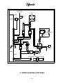
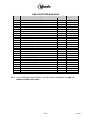
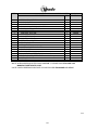
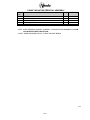
1
SAFETY SECTION
S-1
3/2002
A COMMITMENT TO SAFETY
The Vendo Company is committed to safety in every aspect of our product design. Vendo
is committed to alerting every user to the possible dangers involved in improper handling
or maintenance of our equipment. The servicing of any electrical or mechanical device
involves potential hazards, both to those servicing the equipment and to users of the
equipment. These hazards can arise because of improper maintenance techniques. The
purpose of this manual is to alert everyone servicing Vendo equipment of potentially
hazardous areas, and to provide basic safety guidelines for proper maintenance.
This manual contains various warnings that should be carefully read to minimize the risk
of personal injury to service personnel. This manual also contains service information to
insure that proper methods are followed to avoid damaging the vendor or making it unsafe.
It is also important to understand these warnings are not exhaustive. Vendo could not
possibly know, evaluate, or advise of all of the conceivable ways in which service might be
done. Nor can Vendo predict all of the possible hazardous results. The safety
precautions outlined in this manual provide the basis for an effective safety program. Use
these precautions, along with the service manual, when installing or servicing the vendor.
We strongly recommend a similar commitment to safety by every servicing organization.
Only properly-trained personnel should have access to the interior of the machine.
This will minimize the potential hazards that are inherent in electrical and mechanical
devices. Vendo has no control over the machine once it leaves the premises. It is the
owner or lessor’s responsibility to maintain the vendor in a safe condition. See Section I of
this manual for proper installation procedures and refer to the appropriate service manual
for recommended maintenance procedures. If you have any questions, please contact the
Technical Services Department of the Vendo office nearest you.
SAFETY RULES
•
•
•
•
•
•
•
•
•
•
Read the Safety Manual before installation or service.
Test for proper grounding before installing to reduce the risk of electrical shock and
fire.
Turn off power switch or disconnect power cord from wall outlet before servicing or
clearing product jams. The vending mechanism can trap and pinch hands.
Use only fully-trained service technicians for Power- On servicing.
Remove any product prior to moving a vendor.
Use adequate equipment when moving a vendor.
Always wear eye protection, and protect your hands, face, and body when working
near the refrigeration system.
Use only authorized replacement parts.
Be aware of inherent dangers in rocking or tipping a vending machine.
Always turn power off before plugging or unplugging vendor to wall outlet.
S-2
3/2002
SECTION I: VENDOR INSTALLATION
A.
Vendors are large, bulky machines of significant size and weight. Improper
handling can result in injury. When moving a vendor, carefully plan the route to be
taken and the people and equipment required to accomplish the task safely.
B.
Remove all tape, shipping sealant, and Styrofoam from the vendor. Loosen any
shipping devices used to secure interior parts during shipping. Remove the wooden
shipping base attached to the vendor base by the vendor leveling screws. Make
certain the leveling screws are in place and functional.
C.
Position the vendor three to four inches (7.6 cm to 10.2 cm) from a well-constructed
wall (of a building or otherwise) on a flat, smooth surface.
IMPORTANT: The vendor requires three inches (7.6 cm) of air space from the wall
to ensure proper air circulation to cool the refrigeration unit.
D.
Adjust the leveling screws to compensate for any irregularities on the floor surface.
Ideally, no adjustment will be necessary and the leveling legs will be flush with the
bottom of the vendor. A spirit level is a useful aid to level the vendor. When the
vendor is properly leveled the outer door, when opened, will remain stationary.
Vendors must be level to ensure proper operation and to maintain stability
characteristics. Do not add legs to the vendor.
E.
Check the manufacturer’s nameplate on the left or right side of the vendor’s outer
door to verify the main power supply requirements of the vendor. Be sure the main
power supply matches the requirements of the vendor. To ensure safe operation,
plug the vendor only into a properly grounded outlet.
DO NOT USE EXTENSION CORDS.
F.
Recommended voltage specs = volts required + amps of circuit.
NOTE:
Any power supply variance more than + 10% may cause the vendor to
malfunction.
*
Power outlets must be properly grounded.
*
Power outlets must be properly polarized, where applicable.
Test the outlets using the following information.
(Refer to Figure 1 on Page S-4.)
S-3
3/2002
TYPE 1
STEP 3
LARGE SLOT-LINE 2
NEUTRAL CONTACT (WHITE) 0 - 5 VOLTS
STEP 1
STEP 2
SMALL SLOT-LINE 1
LIVE CONTACT (BLACK)
110 VOLTS
ROUND SOCKET
EARTH CONTACT
(GREEN) 0 VOLTS
EARTH CONTACT SLOT
TYPE 2
SLOT
NEUTRAL CONTACT
(BLUE) 0-5 VOLTS
(GREEN AND YELLOW)
0 VOLTS
STEP 2
STEP 3
STEP 1
SLOT
LIVE CONTACT
(BROWN) 220 VOLTS
POWER CONTACT SOCKET
TYPE 3
NEUTRAL (BLUE) 0-5 VOLTS
OR LIVE (BROWN) 220 VOLTS
STEP 2
STEP 3
POWER CONTACT
SOCKET
EARTH CONTACT
(GREEN AND YELLOW)
0 VOLTS
NEUTRAL (BLUE) 0-5 VOLTS
OR LIVE (BROWN) 220 VOLTS
POWER CONTACT SOCKET
TYPE 4
NEUTRAL (BLUE) 220 VOLTS
OR LIVE (BROWN) 0-5 VOLTS
STEP 1
STEP 2
STEP 3
POWER CONTACT
SOCKET
EARTH CONTACT
(GREEN AND YELLOW)
0 VOLTS
TYPE 5
STEP 1
NEUTRAL (BLUE) 0-5 VOLTS
OR LIVE (BROWN) 220 VOLTS
POWER CONTACT SOCKET
NEUTRAL (BLUE) 0-5 VOLTS
OR LIVE (BROWN) 220 VOLTS
STEP 1
STEP 2
STEP 3
EARTH CONTACT SOCKET
(GREEN AND YELLOW)
0 VOLTS
POWER CONTACT SOCKET
NEUTRAL (BLUE) 0-5 VOLTS
OR LIVE (BROWN) 220 VOLTS
FIGURE 1
CHECKING FOR PROPER GROUNDING AND POLARIZATION
S-4
3/2002
SECTION I: VENDOR INSTALLATION (CONTINUED)
For Type 1 and Type 2 outlets, test for Grounding and Polarization as follows:
1.
With a test device (volt meter or test light), connect one probe to the receptacle’s
neutral contact and the other to the live contact. The test device should show a
reaction.
2.
Connect one probe to the receptacle’s earth contact and the other to the live
contact. The test device should show a reaction.
For Type 3 through Type 5 outlets, test for Grounding as follows:
1.
2.
With a test device (volt meter or test light), determine which of the receptacle’s
power contacts is the live contact.
A.
Connect one probe to the receptacle’s earth contact.
B.
Connect the second probe to the left (or upper) power contact. If a reaction
occurs, this is the live power contact. If a reaction does not occur, move the
second probe to the right (or lower) contact. A reaction should occur,
indicating that this is the live power contact.
Connect one probe to the receptacle’s live power contact (as determined in step 1).
Connect the second probe to the other power contact (neutral). The test device
should show a reaction.
IF THE ABOVE CONDITIONS ARE NOT MET FOR THE GIVEN OUTLET
TYPE, CONTACT A LICENSED ELECTRICIAN AND HAVE THE
NECESSARY CORRECTIONS MADE.
S-5
3/2002
SECTION I: VENDOR INSTALLATION (CONTINUED)
G.
Door Support (Figure 2)
The door support is to ensure that the
outer door closes squarely to the cabinet.
Raising the door can also ensure proper
alignment of the door latch.
FIGURE 2
H.
Door Latch Alignment (Figure 3)
After any door adjustment, the floating quicker
lock assembly should align itself automatically.
The latch assembly is adjustable. To adjust,
loosen the latch bracket mounting screws,
raise or lower the latch assembly into position,
then tighten the mounting screws.
DO NOT INSERT OBJECTS
INTO LOCK CAVITY.
2
1
LATCH
BRACKET
MOUNTING
SCREW
TO FREE OBJECTS, REMOVE
LOCK CAP AS SHOWN
FIGURE 3
WARNING:
KEEP FINGERS AND OTHER OBJECTS OUT OF LOCK CAVITY
NOTE:
Refer to the appropriate parts and service manual for detailed
instructions, operating principles, and recommended maintenance
intervals and procedures.
S-6
3/2002
SECTION II: ELECTRICAL HAZARDS
GENERAL
Vendo vending machines are provided with the appropriate power supply setting for your
area. Some models are equipped with step-down transformers, as required. This enables
the vending machine to operate on different main voltages. Refer to Section I. E. for
information to determine the main power requirements. Refer to the appropriate service
manual for details of step-down transformer operations.
The power sources just mentioned are standard for both household and commercial
lighting and appliances. However, careless or improper handling of electrical circuits can
result in injury or death. Anyone installing, repairing, loading, opening, or otherwise
servicing a vending machine should be alerted to this point. Apply all of the normal
precautions observed in handling electrical circuits, such as:
•
•
•
•
•
•
A.
Refrigeration servicing to be performed by qualified personnel only.
Unplug the vendor or move power switch to off position before servicing or clearing
product jams.
Replace electrical cords if there is any evidence of fraying or other damage.
Keep all protective covers and ground wires in place.
Plug equipment into outlets that are properly grounded and polarized (where
applicable), and protected with fuses or circuit breakers.
All electrical connections must be dry and free of moisture before applying power.
Grounding Systems
Vendo vending machines are provided with the appropriate service cord for the
power supply in your area. The service cord will connect to the matching electrical
outlet. Always ensure that the outlet to be used is properly grounded before
plugging in the vendor. (See pages S-3 through S-5.)
WARNING:
ALWAYS TEST TO VERIFY PROPER GROUNDING PRIOR TO
INSTALLATION TO REDUCE THE RISK OF ELECTRICAL
SHOCK AND FIRE
The electrical grounding system also includes the bonding of all metal components within
the vendor. This involves a system of bonding wires identified by green or green and
yellow marking. The system uses serrated head screws, lock washers, and star washers
to ensure the electrical connection between parts. Maintenance of vending equipment
may involve disassembly. Include the above items when reassembling, even if the
vending machine may appear to function normally without them. Omitting any of these
items can compromise a link in the grounding system. See the appropriate service
manual or kit instructions for components and assembly instructions.
S-7
3/2002
SECTION II: ELECTRICAL HAZARDS (CONTINUED)
B.
Servicing with “Power Off”
For maximum safety, unplug the service cord from the wall outlet before opening
the vendor door. This will remove power from the equipment and avoid electrical
and mechanical hazards. Service personnel should remain aware of possible
hazards from hot components even though electrical power is off. See the
appropriate sections of this manual for further information.
C.
Servicing with “Power On”
Some service situations may require access with the power on. Power on servicing
should be performed only by fully-qualified service technicians. Particular
caution is required in servicing assemblies that combine electrical power and
mechanical movement. Sudden movement (to escape mechanical action) can
result in contact with live circuits and vice versa. It is therefore doubly important to
maintain maximum clearances from both moving parts and live circuits when
servicing.
WARNING:
“POWER-ON” SERVICING SHOULD BE ACCOMPLISHED ONLY BY
FULLY-TRAINED PERSONNEL. SUCH SERVICE BY UNQUALIFIED
INDIVIDUALS CAN BE DANGEROUS.
Power to lighting and refrigeration system is shut off automatically by the electronic
controller when the outer door is opened. Applies to V-Max only.
NOTE:
For power-on servicing of the vendor’s lighting system, turn lighting power on by
accessing the “LIT” test function of the electronic controller (see programming
on inner door). Applies to V-Max only.
For power-on servicing of the vendor’s refrigeration system, turn refrigeration
power on by accessing the “CNPR” test function of the electronic controller (see
programming on inner door). Applies to V-Max only.
S-8
3/2002
SECTION III: MECHANICAL HAZARDS
A.
Servicing of Moving Parts and Assemblies
When servicing assemblies involving moving parts, use extreme caution!! Keep
fingers, hands, loose clothing, hair, tools, or any foreign material clear of
entrapment.
As noted before under the electrical hazards section, Power On servicing should
only be performed by qualified personnel. Refer to and heed the warnings noted in
the electrical hazards section. These warnings refer to the potential hazards
associated with electrical power and moving parts. Always maintain maximum
clearances from electrical and moving parts.
Always install protective covers and guards when reassembling equipment.
WARNING:
THIS VENDING MACHINE INCLUDES MECHANICAL EQUIPMENT
WHICH CAN BE HAZARDOUS IF IMPROPERLY HANDLED OR
SERVICED. USE CAUTION AND CONSULT THE VENDO SAFETY
MANUAL AND THE VENDO SERVICE MANUAL FOR ADDITIONAL
SAFETY INFORMATION.
WARNING
WARNING
RISK OF SHOCK !
ELECTRICAL!
RISK OF ENTRAPMENT !
S-9
3/2002
SECTION IV: REFRIGERATION HAZARDS
GENERAL
Refrigeration systems involve both electrical power and mechanical action. These
systems may present any of the potential dangers shown in the sections on electrical and
mechanical hazards contained in this manual. See Sections II and III for further
information.
A.
Compressed Refrigerant
Refrigeration systems involve the compression and evaporation of gases. The
pressures contained represent a potential hazard if suddenly released in confined
areas. Caution is required when performing maintenance tests or repairs. All
testing of sealed refrigeration systems must be done by trained personnel who are
familiar with the systems and pressures involved.
B.
Physical Protection
The accidental release of refrigerant gases can result in physical injuries. Always
wear protective glasses and protect your hands, face, and body when working near
the refrigeration system.
WARNING:
ALWAYS WEAR EYE PROTECTION AND PROTECT YOUR HANDS,
FACE, AND BODY WHEN WORKING NEAR THE REFRIGERATION
SYSTEM.
SECTION V: TEMPERATURE HAZARDS
GENERAL
Maintenance personnel should be alerted to the potential hazards from hot metal surfaces.
High temperatures may be present throughout the refrigeration system even though
electrical power has been removed.
S-10
3/2002
SECTION VI: SUBSTITUTIONS AND MODIFICATIONS
GENERAL
Unauthorized changes or the substitution of unauthorized parts can compromise the
equipment designs. This can result in unsafe conditions for either the service
personnel or the equipment users. Always refer to the appropriate parts and service
manual for replacement parts and maintenance instructions. If questions arise,
contact the Technical Services Department of the Vendo office in your area.
When servicing the vending machine, always reassemble all components to their
original location and position. Maintain the correct routing for tubing, electrical wiring,
etc. Replace all clamps, brackets, and guides to their original locations. Replace all
tubing, sleeving, insulating material, and protective covers to their original condition.
WARNING:
VENDO EQUIPMENT HAS BEEN PROVIDED WITH APPROPRIATE
PROTECTIVE DEVICES TO PROTECT AGAINST THE POSSIBILITY
OF OVERHEATING AND FIRE AS A RESULT OF EQUIPMENT OR
COMPONENT FAILURES. SUBSTITUTION, MODIFICATION, OR
BYPASSING OF SUCH PROTECTIVE DEVICES CAN CREATE
DANGEROUS CONDITIONS.
PROTECTIVE CIRCUITS SHOULD
NEVER BE BYPASSED, AND FAILED PROTECTIVE DEVICES MUST
BE REPLACED ONLY WITH FACTORY-AUTHORIZED PARTS.
A.
Service Cord Replacement
Vendo vending machines are furnished with unique power supply cords. If
replacement becomes necessary, consult the appropriate parts and service manual
and order the correct replacement cord for the model of vending machine in
question. Do not use substitute replacement cords. Only authorized service
personnel with appropriate training should replace the vending machine service
cord. If a question should arise concerning which service cord to order, contact the
Technical Services Department of the Vendo office in your area.
S-11
3/2002
SECTION VI: SUBSTITUTIONS AND MODIFICATIONS (CONTINUED)
WARNING:
THIS APPLIANCE MUST BE EARTHED.
IMPORTANT!
The wires in the main leads are colored in accordance with the following code:
110v/120v
Green
White
Black
220v/240v
Green and Yellow ............................ Earth
Blue................................................... Neutral
Brown ............................................... Live
S-12
3/2002
SECTION VII: CONSUMER SAFETY WARNING
WARNING:
VENDOR CAN BE OVERTURNED IF SUFFICIENT FORCE IS
APPLIED, AND MAY RESULT IN SERIOUS INJURY OR DEATH.
GENERAL
There have been incidents, including fatalities, when vending machines have been
vandalized by being pulled over in an attempt to obtain free product or money.
To warn of the danger involved in tipping, shaking, or rocking the vending machine, a
decal has been designed to be affixed to vending machines. (One such decal is
supplied with the vending machine.) Vendo will supply sufficient decals to be placed
on all machines, on request. If you have any questions, contact the Technical Services
Department of the Vendo office in your area.
THE FOLLOWING DECAL SHOULD BE PLACED IN A POSITION ON
THE VENDOR CONTROL PANEL AT EYE LEVEL.
WARNING
Never rock or tilt.
Machine can fall over
and cause serious
injury or death.
Vending machine will
not dispense free
product.
MISE EN
GARDE
Ne jamais secouer
ou incliner.
Le distributeur peut
se renverser et causer
des blessures graves
ou la morte.
Cette machine ne
distribue pas de
produits gratuitement.
389611A
ENGLISH
389611-1A
FRENCH
S-13
AVISO
Nunca voltie o incline
esta maquina.
Puede caer sobre usted
y cauzarle heridas
graves o matarle.
Esta Vendomatica no
provee producto gratis.
389611-2A
SPANISH
3/2002
GAS ISLAND VENDOR INSTALLATION PROTOCOL
Vendo Gas Island Vending Machines have been evaluated by UL (Underwriters
Laboratories Inc.®) for placement at service stations which the NFPA (National Fire
Protection Association) considers a hazardous location. These vendors must be
correctly installed and inspected per the following protocol before they are put into
service.
A. Vendor is to be installed in accordance with the National Electrical Code, NFPA 70,
Article 514 - Gasoline Dispensing and Service Stations, NFPA 30A - Automotive and
Marine Service Station Code, and the Local Authority Having Jurisdiction.
IMPORTANT - Compliance includes direct wiring of the vendor to the voltage source
utilizing proper metal conduit and circuit protection.
B. When installed on support base, the vendor can be installed in an 18-inch high Class
I, Group D, Division 2 Hazardous Location. Additionally, the vendor must be installed
at least 18 inches from any flammable liquid dispensing device.
Vendor support base is to be attached to vendor as shown by view on page S-15.
Vendor should be securely bolted in place using ½-inch nominal diameter hardware
as a minimum.
C. IMPORTANT: FOR ANY INSTALLATION REQUIRING LEVELING OF THE
VENDOR, IT IS MANDATORY TO OBTAIN APPROVAL OF THE LOCAL
AUTHORITY HAVING JURISDICTION. THERE ARE NO EXCEPTIONS.
To level more than 1/8 inch, it is suggested to follow these guidelines:
1. Shimming of one or more mounting points should be done with solid steel,
minimum thickness of 1/8 inch. Solid aluminum is acceptable.
2. It is not acceptable to place shims under all (4) mounting points.
3. Shims should be a minimum of 2 ½ inch x 2 ½ inch square or 2 ½ inch diameter.
4. Shim should have a hole, (approximately ½ inch diameter), through the center in
the same manner as the GIV pedestal foot.
5. Shim should be protected against corrosion by painting, plating, etc.
6. IMPORTANT: Hold down bolt should be a solid, continuous bolt.
It is MANDATORY that all installations requiring leveling be approved by the
LOCAL AUTHORITY HAVING JURISDICTION.
D. Warning - Power tools with arcing and sparking parts, such as electric drills, should
not be used in any hazardous locations during the installation of this vendor.
E. The dispensing area shall be in clear view of the attendant at all times, and placing or
allowing any obstacle to come between the dispensing area and the attendant control
area shall be prohibited.
F. Upon completion of the installation, the Local Fire Marshall, or Authority Having
Jurisdiction, must verify the installation complies with the codes shown in Item A.
After authorization, the vendor may be placed into operation.
S-14
3/2002
MOUNTING TO PEDESTAL
VENDOR
PEDESTAL
FLAT WASHER
LOCK WASHER
HEX BOLT 1/2"-13x1 1/2"
FRONT AND REAR COVER
IMPORTANT - INSTALLATION REQUIREMENTS
Electrical equipment, such as vending machines, installed within a 20-ft. radius of a
gasoline dispensing unit must meet safety specifications of the National Electrical
Code, NFPA 70 - Article 514 - Gasoline Dispensing and Service Stations, NFPA 30A Automobile and Marine Service Station Code, and the Local Authority Having
Jurisdiction.
Safety Specifications are:
•
•
•
•
•
The vending machine must be UL Listed for installation near gasoline dispensing
equipment.
The vending machine is UL Listed for use in an 18-inch high Class I, Group D,
Division 2 Hazardous Location.
Installation requires ON-SITE approval of Local Fire Marshall, or Authority Having
Jurisdiction.
The vending machine should be securely bolted in place using ½” nominal diameter
hardware as a minimum. Use template provided on pedestal carton for mounting
locations. If vendor requires leveling more than 1/8 inch, refer to Page S-14.
The vending machine must be direct-wired to the voltage source utilizing proper
metal conduit and circuit protection.
Note: There are unique safety and approval considerations required for placement of a
vendor at the gasoline island which will require a non-standard vending machine. A
standard vending machine located at or near the gasoline dispensing area will create
unacceptable risks and will not meet safety agency requirements.
S-15
3/2002
PARTS, SALES, & SERVICE CENTERS OF VENDO/SANDEN COMPANY
AREA
United States,
Canada
Japan
Europe, Mid-East,
Africa, Mid-Asia
Australia,
New Zealand
Singapore,
Hong Kong,
Indonesia,
Philippines, India
Taiwan
Belgium
England
Italy
Spain
ADDRESS
The Vendo Company
7209 N. Ingram
Fresno, CA 93650 U.S.A.
Sanden International Corporation
31-7 Taito 1-Chome
Taito-ku
Tokyo 110, Japan
Vendo GMBH
Spangerstr. 22, P.O. Box 130940
40599 Dusseldorf
Germany
Sanden International Pty. Ltd.
54 Allingham St., Condell Park
N.S.W. 2200
Australia
Sanden International (Singapore) Pte., Ltd.
Sanden House, 25, Ang Mo Kio St. 65
Singapore 569062
The Republic of Singapore
Sanden International Taiwan Corp.
No, 21-6, Sec 1
Tun Hwa S. Rd., Taipei, Taiwan
Taiwan, ROC
N.V. Vendo Benelux, S.A.
Industrial Research Park N.O.H.
13 Font St. Landry
1120 Brussels
Belgium
Vendhall, Ltd.
Unit 17, The Basingstoke Enterprise Centre
Westham Lane, Worting Rd,
Basingstoke, Hants RG22, 6NQ
Great Britain
Vendo Italy S.p.A.
Casella Postale 9
1-15033 Casale Monferrato
Italy
Vendo Iberia, S.A.
C/ Sant Ferran No. 92
Poligono Industrial la Almeda, Sector P-1
08940 Cornella, (Barcelona), Spain
S-16
PHONE NUMBERS
Tel: (559) 439-1770
Fax: (559) 439-2083
Tel: (81) 3-3835-1321
Fax: (81) 3-3833-7096
Tel: (49) 211-74-039-0
Fax: (49) 211-7488541
Tel: 61-2-9791-0999
Fax: 61-2-9791-9029
Tel:
Fax:
65-482-5500
65-482-1697
Tel: 886-2-570-6106
Fax: 886-2-577-1959
Tel: 32-2-268-2595
Fax: 32-2-268-2862
Tel: 44-1256-479309
Fax: 44-1256-844469
Tel: 39-142-335111
Fax: 39-142-5623-48
Tel: 343-474-1555
Fax: 343-474-1842
3/2002
PARTS, SALES, & SERVICE CENTERS OF VENDO/SANDEN COMPANY
FOR LATIN AMERICA
AREA
Mexico
Central America
Chile
Brazil
South America
ADDRESS
Vendo de Mexico
Camino Real de Toluca No. 154
Col. Bellavista
01140 Mexico D.F. Mexico
The Vendo Company
7209 N. Ingram
Fresno, CA 93650 U.S.A.
Pelp Internacional, S.A.
4560 El Rosal
Huechuraba, Santiago, Chile
Cimaq Industria e Comercio de Maq,
Ltda.
Estrada Uniao e Industria, 9.120 Itaipava
25730-730 Petropolis
Rio de Janeiro, Brazil
The Vendo Company
7209 N. Ingram Ave.
Fresno, CA 93650 U.S.A.
S-17
PHONE NUMBERS
Tel: (525) 515-9745
Fax: (525) 277-0111
Tel: (559) 439-1770
Fax: (559) 439-2083
Tel: (562) 243-9710
Fax: (562) 740-0504
Tel: (55242) 22-2666
Fax: (55242) 22-3244
Tel: (559) 439-1770
Fax: (559) 439-2083
3/2002
NOTES
S-18
3/2002
GENERAL INFORMATION
G-1
8/2002
GENERAL INFORMATION
This manual contains programming, operation, and complete parts and electrical wiring
diagrams.
The V-MAX controller is a microprocessor which will permit pricing per selection from
0.00 to 99.99. This machine also has space-to-sales programming.
Specifications:
MODEL
V-MAX 576
V-MAX
V-MAX
V-MAX
540/720
630/840
512/680
SELECTIONS
7-8
9-10
9-10
9 or 13
DIMENSIONS (HEIGHT X WIDTH X DEPTH)
CURVED DOOR
72” x 32 ½” 72” x 39 ½“ 79” x 39 ½ “
Not
x 34 ¾”
x 35”
x 35”
Available
FLAT DOOR
72” x 32 ½” 72” x 39 ½” 79” x 39 ½”
Not
x 31 ½”
x 32 ½”
x 32 ½”
Available
MARKETING VENDOR
Not
Not
Not
72” x 39 ½”
Available
Available
Available
x 34 ¾”
ROBO DOOR
Not
72” x 39 ½” 79” x 39 ½”
Not
Available
x 32 ½”
x 32 ½”
Available
SINGLE COLUMNS
8
10
10
10
51/68
84
72
72
CAPACITY 12 oz. CAN***
26
36
30
30
16 oz. GLASS
PER
30
38
32
32
COLUMN 20 oz. **
SHIPPING WEIGHT
640 lbs
685 Ibs
750 Ibs
758 lbs
OPERATION VOLTAGE
115v 60 Hz. 115v 60 Hz. 115v 60 Hz. 115v 60 Hz.
AMP. RATING
10
10
10
10
REFRIGERATION
115v 60 Hz. 115v 60 Hz. 115v 60 Hz. 115v 60 Hz.
VOLTAGE
V-MAX
603/800
9 or 13
Not
Available
Not
Available
79” x 39 ½”
x 34 ¾”
Not
Available
10
60/80
32
36
818 lbs
115v 60 Hz.
10
115v 60 Hz.
*Dimensions and shipping weight will vary slightly due to manufacturing tolerances,
shipping boards and whether or not coinage is installed.
** 20 oz. PET capacity may vary based on the shape and size of the bottle.
***12 oz. Can capacities are listed using a 4-deep set up.
INITIAL SET-UP
G-2
8/2002
A. UNPACKING
Remove all plastic film, cardboard, and tape from the outside of the vendor. Loosen
any shipping devices used to secure interior parts during shipment (backspacer,
shims, or spacers).
To remove shipping boards from base, raise vendor on a well-stabilized lifting
device. Remove the leveling bolt which holds the boards in place and remove the
boards. Replace bolts to equal heights in the threaded holes.
Another method to remove shipping boards is to split the boards apart. Using a
pinch bar or a heavy screwdriver and hammer, insert tool into the slots and force the
board apart.
B. POSITIONING
IMPORTANT: PLACE THE VENDOR IN DESIRED LOCATION AT LEAST THREE
TO FOUR INCHES (8 TO 10 CENTIMETERS) AWAY FROM ANY REAR
OBSTRUCTION. This is for proper air flow through the refrigeration compartment.
The refrigeration system requires front to rear air circulation for proper operation.
C. POWER SUPPLY CONNECTION
CAUTION: DO NOT USE AN EXTENSION CORD!
The vendor’s power requirements will vary depending upon the country it was
purchased for. To verify the power requirements of the vendor, check the serial plate
located on the hinged side of the outer door (see Figure 4 on page G-4). The power
requirements are listed on the serial plate.
To insure safe operation of the vendor, the vendor’s power supply must be a
properly grounded and polarized outlet. Before plugging the vendor into the outlet,
test the outlet to confirm it will meet the vendor’s power requirements. If the power
supply of the outlet is different from the power requirements of the vendor, a
transformer may be necessary.
If the power requirements are not properly met, contact a licensed electrician and
have the necessary correction made.
Should you require additional information, contact the Technical Services
Department of the Vendo office in your area.
G-3
8/2002
APPROVED FOR OUTDOOR USE
MODEL
BASIC
UNIT
SERIAL NO.
CHARGE
LR 13085
AMPS
OZ. R-134a
MIN. TEST PRESSURE APPLIED - PSI
HIGH SIDE 235
LOW SIDE 140
R
239L
endo
THE VENDO COMPANY FRESNO, CA.
VENDING MACHINE
REFRIGERATED
105/115v
50/60
1
VOLT
CYCLE
PHASE
POWER REQUIREMENTS
FIGURE 4
NOTE: The Model number of the vending machine is located on the top left hand corner of the
serial plate. Do Not use the “BASIC UNIT” number. The BASIC UNIT number is
the cabinet size, which is used on a number of different machines. A typical model
number could read “540CCD00029”. The 540 is the model number, CCD represents the
product line of the vendor and the remaining digits tell what options are included.
G-4
8/2002
COIN INSERT
B
COIN INSERT
A
STYLE A
STYLE B
STYLE C
STYLE F
COIN INSTRUCTION LABEL
PRICE DISPLAY
PRICE DISPLAY
COIN INSTRUCTION LABEL
FIGURE 5
FIGURE 6
LABEL INSTALLATION
COIN INSTRUCTION LABEL & PRICE LABEL APPLICATION:
Apply labels to a clean and dry surface. Peel backing from label and apply with firm,
even pressure.
INSTRUCTION LABEL
(Refer to Figure 5 for the following information.)
Coin insert “A” has a separate validator opening, and insert “B” shows the validator
opening built into the coin insert. Apply instruction label to area shown (as needed by
the vendor).
FLAVOR LABELS INSTALLATION:
In Figures 6 & 7, corresponding styles are indicated by A, B, C, D, E, or F notations.
Insert flavor labels to the side or top of selection window or button depending on the
style. See Figure 6 for selection style. Rear views of windows and buttons are shown
in Figure 7. Arrows point the direction to insert labels.
Selection window and selection button labels identify product contained in stack
columns.
STYLE- A
STYLE- F
STYLE- D
STYLE- B
STYLE- E
STYLE- C
NOTE: The selection panel used with
styles D and E is not depicted in Figure 6.
FIGURE 7
G-5
8/2002
COMPRESSOR
DRAIN TUBE
CONDENSATION PAN
CONDENSER FAN BRACKET
FIGURE 8
FIGURE 9
ALIGNMENT CHECKS
DOOR RAMP CHECK:
The door support is to insure that the outer door closes squarely to the cabinet.
Raising the door can also insure proper alignment of the door latch (see Figure 8).
REFRIGERATION AREA CHECK:
Check the position of the condensation pan (see Figure 9). The correct position of the
pan is between the compressor and the condenser fan bracket. Be sure the drain
tube is clipped to the pan and is free of kinks. A water trap is installed into the
condensation pan and will prevent warm, moist air from reaching the evaporator area.
G-6
8/2002
LOADING INSTRUCTIONS
BASIC LOAD SET-UP:
The V-Max machine is capable of vending a variety of products. For specific
information, refer to the product set-up label on the machine inner door or contact
the Technical Services Department of the Vendo office in your area.
Load product evenly. Bottles are loaded with crown end placed toward the back of
the column. In initial loading, prime the machine by advancing the product into the
buckets. To advance product into buckets, use the vend test function of the
electronic controller. When the bucket is loaded, the column is ready to vend.
PRIME ALL COLUMNS DURING INITIAL PRODUCT LOADING
G-7
8/2002
VEND MECHANISM PARTS DESCRIPTION
The parts listed below are part of the vend motor mechanism (refer to Figure 10 on
page G-9). One mechanism is required per column. The parts are interchangeable.
Settings will differ between single, double, triple, and quadruple depth.
VEND MOTOR ASSEMBLY: P/N 1115821
The motor is attached to the mech. plate by three screws.
TIMING CAM: P/N 1113236, RETAINER: P/N 1113244
The motor cam assembly consists of two parts, the cam and the cam retainer. The cam
controls the vend cycle. The cam is attached to the motor by the cam retainer. The
retainer rotates left or right, and provides for single, double, triple, or quadruple depth
operation.
SOLD-OUT SWITCH: P/N 368299
There is one sold-out switch above the vend motor. The sold-out switch is actuated by
the sold-out flap when the column is empty. It prevents the motor from running when the
columns are empty.
STEEL BUCKET: P/N 1120146
The vend bucket holds the product(s) in a “ready to vend” position at the base of each
column.
MOTOR COUPLING: P/N 1076465
The adapter coupling couples the motor to the bucket. It is located behind the motor, on
the motor shaft.
ANTI-THEFT CLIP: P/N 389712
The anti-tilt clip prevents product from dropping out of the bucket if the vendor is tilted.
The anti-theft clips are located in the bucket.
GATE: P/N 1121282
The gate holds product above the vend bucket.
G-8
8/2002
GATE LINK: P/N 1120140
The rotation of the vend bucket moves the gate link. This opens the gate, allowing one
layer of product to drop into the bucket.
GAGE BAR: P/N 1111651
The gage bar holds the product(s) inside the bucket. It also regulates which product is
vended first when double, triple or quadruple settings are used (See page G-10 for
motor cam settings).
GAGE BAR CLIPS: P/N 1066104(white), 1066112(black), 1066112-1(gray),
1121704(gray), 1122103(black)
Gage bar clips are attached to the gage bar to create multiple steps when vending
product double, triple, or quadruple depths. (See product set-up label on inner door for
details.)
ANTI-TILT CLIP
GATE
GATE
LINK
SOLD-OUT
LEVER
SPRING
BUCKET
SWITCH
MOUNT
COUPLER
GAGE BAR
MOTOR CAM
GAGE BAR CLIPS
FIGURE 10
G-9
8/2002
VEND CYCLE
Several operations take place during the vend cycle. When a selection is made, the cam
and bucket rotate, product is dispensed and the bucket is then reloaded. The sequence of
these operations changes slightly when the column’s depth setting is changed. With the
single-depth setting, one purchase is made and the bucket is reloaded. The cam
sequence occurs one time per bucket revolution. With the double-depth setting, two
purchases are made before the bucket is reloaded, and the cam sequence occurs twice
per bucket revolution. With triple-depth setting, three purchases are made and the cam
sequences three times per bucket revolution. With quadruple-depth setting, four
purchases are made and the cam sequences four times per bucket revolution.
PURCHASE SEQUENCE: (See Figure 11, quadruple-depth setting pictured)
PS 1.
Customer inserts money.
PS 2.
The coinage reports credit to the vending machine electronic controller.
Established credit is displayed on the digital display located near the coin insert
slot.
PS 3.
Customer presses a selection button.
PS 4.
The controller receives the signal from the selection switch and (if sufficient credit
exists), energizes the corresponding vend motor.
PS 5.
The vend motor rotates the bucket and cam. As the cam rotates, the motor position
switch actuator raises to the outer surface of the cam. This closes the switch,
which signals the controller to remove credit.
PS 6.
Product is immediately dispensed. The motor and cam continue to rotate until the
motor position switch actuator drops into the low part of the cam.
PS 7.
Motor stops.
ITEM 1
IN STAND-BY
POSITION
ITEM 2
IS PS-5 - PS-6
CAM
3
3
1
2
1
2
2
3
4
4
1
CAM
RETAINER
4
FIGURE 11
NOTE: The numbers on the cam reflect the number of vends allowed per cycle.
G-10
8/2002
RELOADING SEQUENCE (See Figure 12.)
RS 1. The gate link rests at a locked position in a cut-out on the mech. plate. This locked
position prevents the gate from opening out of sequence.
RS 2. The gate link is guided by a slot in the mech. plate and is actuated by a ridge on
the bucket. As the bucket turns, the link is moved out of the locked position.
RS 3. As the link rises, the gate is opened. The spring maintains pressure on the link and
the gate.
RS 4. Product falls into the bucket, the link returns to the locked position and the gate is
closed.
RS 5. The bucket releases the gate link causing the gate to rest against the product.
RS 6. As the product falls into the bucket, the link returns to the locked position and the
gate is closed.
RS 7. The product remaining in the column is held by the closed gate, keeping it above
the bucket.
RS 8. The bucket stops, loaded with product, and is ready to vend.
FIGURE 12
ITEM 1
ITEM 2
RS-1
RS-8
GATE
GATE
LINK
GATE
LINK
GATE
SPRING
SPRING
BUCKET
BUCKET
ITEM 3
ITEM 4
ITEM 5
ITEM 6
ITEM 7
RS-2
RS-3
RS-4
RS-5
RS-6
RS-7
G-11
8/2002
NOTES
G-12
8/2002
9.1 PROGRAMMING SECTION
PC-1
All programming of the V-Max is done in the service mode as indicated in the following steps
below. The main service modes are indicated in white text and the sub-modes are indicate in
black text.
Example:
tIne
Time/Date Setting Mode
YeAr
nth
dATe
Year Setting
Month Setting
Date Setting
Hour Hour Setting
Dst
Daylight Saving Time
PC-2
THREE BUTTON PROGRAMMING
All programming of the V-Max options are done in the service mode. To enter the service
mode, open the vendor door find the service mode button located on the control board and then
press and release the service mode button which is located on the controller board. (See figure
1).
To toggle though all the service mode you will need to use the service mode button or
secondary service switch.
The first three selection buttons are used to navigate through the programming as follows:
Button
Description
Usage
Selection Button 1
Up/Down
Increase/Decrease, Next/Previous
Selection Button 2
Enter
Go to sub-level, activate function
Selection Button 3
Return
Exit, Go back to the previous level
Note: Three button programming is only used for the following:
1. Tine function and all it’s sub codes.
2. Open door data retrieval.
The controller will automatically return to the Open-Door Sales Mode if:
1. No information from the selection switches is received within approximately 30 seconds.
2. The service mode button is pressed a second time.
3. The (Return) button is pressed.
When the programming is entered, any established credit is returned. When and if the door is
closed, the controller will exit the service mode and return to the sales mode.
PC-3
V-MAX CONTROLLER
SERVICE MODE
BUTTON
TEMPERATURE
SENSOR
DEX
PORT
DISPLAY
J1
J3
J4
VENDO
AUX
J5
SELECTION
SWITCH
RESERVED
J6
J7
RELAY
CONTROLS
NOT
USEABLE
CONTROL
BOARD
SERIAL NUMBER
LOCATED HERE
J11
J9
NOT
USEABLE
J10
POWER
IN
9.1
J12
J13
J8
MDB PORT
Figure 1
PC-4
VEND
MOTOR AND
DOOR SWITCH
SET-UP AND CODE DESCRIPTION
Eror
Error Display Mode
If selection button two is pressed at the “Eror” prompt, the controller will enter the Error Display
Mode. If no errors have occurred, the display will show ”nonE”. If an error has been detected
since the last error reset, the display will show the first error summary code that has occurred. If
selection button three is pressed while displaying any summary code, the controller will return to
the “Eror” prompt.
Note: See figure 2 for Error Code Map located on page PC-5.
EXAMPLE: “COLJ” would indicate a column jam error.
Clearing an Error
If selection button two is pressed and held for two seconds during the display of the detailed
error code, that error will be cleared. If any other detailed errors exist, the next error will now be
displayed. If no other errors of this type exist, the next error summary code will now be
displayed, or “nonE” if no other errors exist.
COIn Coin Pay-out/Tube Fill Mode
If selection button one is pressed at the “COIN” prompt, the controller will enter the Coin PayOut Mode. The display will show the lowest coin value that can be paid out (.5, .10, .25 etc).
Using the selection button one, two, or three will allow the operator to toggle through the cointube selections. If any of the buttons (e.g.1-3) is pressed, a pay-out of the displayed value will
be made. Coins will continue to pay-out as long as that selection button is held down.
EXAMPLE: If selection button one is pressed while 5 cents is displayed it will pay-out a
nickel.
Note: If using a four tube coin changer selection button four will allow you to pay-out the
displayed value.
When the controller enters the coin tube fill mode. The operator is allowed to deposit any coin
into the coin changer’s acceptor when that coin’s tube is not full. The tube inventory level will be
displayed after each coin is accepted.
PC-5
ERROR CODES
Open door error code status (as displayed)
nonE
Eror
Summary level error codes (as displayed)
Detail level error codes ( as displayed)
DESCRIPTION
No errors exist
One or more errors exist
COLJ
Vend mechanism summary error
CJXX
Column jam in column XX
SEL
Selection switch summary error
S
SSXX
Selection switch XX is stuck closed
StS
Space-to-sales summary error
UCXX
Column XX is not assigned to a selection
USXX
Selection switch XX is not assigned
CHn
Coin changer summary error
Detailed error codes are cleared by
pressing Selection button 2 for 2
seconds when displayed or
automatically by the following.
Complete a test for column XX
Switch XX opens
Column XX is assigned
Selection XX is assigned
G
CC
tS
IC
tJ
CrCH
EE
nJ
LA
dIS
rout
bUAL
bC
bFUL
bILL
bJ
brCH
bOPn
bS
Crdr
CrC
CrXY
rFrG
SEnS
CnPr
Htr
OtHr
dS
rAn
ACLO
Changer communication stopped
Tube sense error reported by changer
Changer inlet chute blocked
Pay out tube jam reported by changer
Check sum error reported by changer
Excessive escrow attempts
Coin jam reported by changer
Coin acceptance rate is low
Unconnected acceptor reported by changer
Coin routing error reported by changer
Bill validator summary error
Validator communications stopped
Bill stacker full reported by validator
Defective motor reported by validator
Bill jam reported by validator
Check sum error reported by validator
Bill stacker open reported by validator
Bill sensor error reported by validator
Card reader summary error
Reader communications stopped
Error *code X, sub-code Y reported by reader
Refrigeration system summary error
Temperature sensor unplugged/defective
Cooling system not cooling
heating system not heating
Other vendor summary errors
Door open for 1 hour
Check sum error for service mode setting
AC voltage is low
PC-6
Changer communication normal
Changer corrected
Coin is sensed
Changer corrected
Changer corrected
Coin is sensed
Changer corrected
Coin acceptance rate improves
Acceptor properly connected
Coin is routed properly
Validator communications normal
Bills removed from stacker
Validator corrected
Validator corrected
Validator corrected
Validator corrected
Validator corrected
Reader communications normal
Reader corrected
Sensor connected/replaced
System cooling at least 1ºF per hour
System heating at least 1ºF per hour
Door Closed
Any service mode setting changed
SF
IS
Ib
Scale factor incompatibility
Vendor inlet coin chute sensor is blocked
Vendor inlet coin chute is blocked
Scale factor is located
Blockage is removed
Coin is detected by the changer
Figure 2
SET-UP AND CODE DESCRIPTION (CONTINUED)
tESt Test Mode
If selection button one is pressed at the “tESt” prompt, the controller will enter the Test Mode.
Upon entry into the test mode the display will show the first summary test, “CO 1”. Pressing
selection button one or two will toggle through the column selections. Pressing selection button
three will test vend the displayed column. In order to exit the setting the operator need to press
the service mode button or close the outer door
LItE
Test Lights
If the fifth selection button is pressed at the “tESt” prompt, the “LItE” mode is displayed. If the
fifth button is pressed again at the “LItE” prompt, the controller will activate the test status of the
lights. Pressing the fifth button again de-activates the test status of the lights.
CnPr Compressor Test Mode
If the sixth selection button is pressed at the “tESt” prompt, the “CnPr” mode is displayed. If the
sixth button is pressed again at the “CnPr” prompt, the controller will activate the test status of
the compressor. Pressing the sixth button again de-activates the test status of the compressor.
COSt Cost Setting Mode (Multi-Price)
The purpose of this mode is to enable the controller to set the vend price for each of the
selections. If selection button one thru ten is pressed at the “COSt” prompt, the display will
toggle “SL X” “00” (“X” will indicate the selection buttons and “00” will indicate the selection
price). Pressing the same button again will increase or decrease the price. In order to save the
selection price the operator need to either press the service mode button or close the outer
door.
Cost Setting Mode (Single-Price)
The purpose of this mode is to enable the controller to set the vend price for each of the
selections. If selection button one is pressed at the “COSt” prompt, the display will toggle
“SPRl” “00” (“00” will indicate the selection price). Pressing the same button again will increase
or decrease the price. In order to save the selection price the operator need to either press the
service mode button or close the outer door.
Note: Make sure 1.4 is set properly in configuration group 1 mode.
Example: 1.4 “y” = Enabled is single price.
PC-7
1.4 “n” = Disabled is multi-price.
SET-UP AND CODE DESCRIPTION (CONTINUED)
OPt 1 Option Group 1 Mode
If selection button one is pressed at the “OPt1” prompt, the controller will enter the Option Group
1 Mode. The purpose of this mode is to allow the controller to select the group 1 configuration
options desired. Upon entry into this setting the display will show “1.1 y” where “y” is for enable
or “n” for disable. Pressing selection buttons 1-5 will display the available options listed below.
EXAMPLE: “1.1 y” = Option group 1 enable
“1.1 n” = Option group 1 disable
Selection
No.
Button #1
Button #2
Button #3
Button #4
Button #5
Button #6
Display
Description
1.1 “y” or “n”
1.2 “y” or “n”
1.3 “y” or “n”
1.4 “y” or “n”
1.5 “y” or “n”
Force vend enable or disable
Bill Escrow enable or disable
Error/Sold Out indicator “o” enabled or disabled
Single Price enable/Multi-Price disabled
Sales count by price is enable/ By selection is
disable if “Y” = “Yes”
Sales count by selection is enable/ By price is
disable if “N” = “No”
Displays controller and software version
Toggle software info.
OPt2 Option Group 2 Mode
If selection button one is pressed at the “OPt2” prompt, the controller will enter the Option Group
2 Mode. The purpose of this mode is to allow the controller to select the group 2 configuration
options desired.
Selection No.
Button #1
Display
2.1 “y” or “n”
Button #2
Button #3
2.2 “y” or “n”
2.3 “y” or “n”
Button #4
2.4 “y” or “n”
Description
“Y”- Correct change light indicator is disabled.
“N”- Correct change light indicator operates as
normal.
Allow Overpay enabled or disabled
“Y”- Save Credit Timer is enabled holds credit
for 5 minutes.
“N”- Save Credit Timer is disabled in which
credit never times out.
Multi-Vend enabled / Single vend disabled
PC-8
SET-UP AND CODE DESCRIPTION (CONTINUED)
SSS
Space-to-Sales Setting Mode
If any selection button is pressed at the “SSSS” prompt, the controller will enter the Space-toSales option. Upon entry into this setting the display will show the current option setting.
Pressing any selection button for 3 seconds will change the space-to-sales configuration as
listed below. The display will show “STS nn” where “nn” is indicates the desired option.
For proper configuration settings refer to the label located on the inner door shear
panel (See figure 3)
SPACE-TO-SALES CONFIGURATIONS
ST10 STS9 STS8 STS7 STS6 STS5 STS4 STS3 STS2
STS1
SEL# COL COL
COL
COL
COL
COL
COL
COL
COL
COL
1
1
1,2
1
1
1,2,3
1,2
~
~
ALL
NONE
2
2
1,2
2
2
1,2,3
1,2
~
~
ALL
NONE
3
3
3
3
3
1,2,3
3
~
~
ALL
NONE
4
4
4
4
4
4
4
~
~
ALL
NONE
5
5
5
5
5
5
5
~
~
ALL
NONE
6
6
6
6
6
6
6
~
~
ALL
NONE
7
7
7
7
7
7
7
~
~
ALL
NONE
8
8
8
8
~
8
8
~
~
ALL
NONE
9
9
9
~
~
9
~
~
~
ALL
NONE
10
10
10
~
~
10
~
~
~
ALL
NONE
FIGURE 3
Note: If none of the space-to-sales configuration is suitable the operator can use the
Custom Space-to Sales Setting Mode.
CSSS Custom Space-to-Sales Setting mode
If any selection button is pressed at the “CSSS” prompt, the controller will enter the Custom
Space-to-Sales option. Upon entry into this setting the display will show the current selection
setting followed by the columns connected to that selection button.
Programming Connection Option
If any selection button is pressed for more then 3 seconds while at the “CSSS” prompt the
controller will enter the Custom Space-to-Sales Programming Option. Pressing selection button
one or two will increase or decrease the column number displayed. Pressing selection button
three will actuate the changed connection status of the column number displayed. Pressing
selection button four will save the connection changes and return the controller to the “CSSS”
prompt.
PC-9
SET-UP AND CODE DESCRIPTION (CONTINUED)
Cddr Closed Door Data Retrieval Mode
If selection buttons 1-4 are pressed at the “Cddr” prompt, the controller will enter the Closed
Door Data Retrieval Mode by displaying “XXXX” where “XXXX” is the password. By pressing
button number one the controller will display the current password while the first digit is flashing.
By pressing the selection button again it will allow you to change the password. By following the
above direction you may customize your password by using buttons 1-4. Buttons 1-4 will only
change the digit from 0 to 6 (see note below). In order to save the password the operator
needs to either press the service mode button or close the outer door.
Note: If one of the digits in the password is “0” it will be disabled since selection button “0”
does not exist.
rFrG Refrigeration Mode
If selection button one is pressed at the “rFrG” prompt, the controller will enter the Refrigeration
Control Mode by displaying “norn”. Pressing selection button one again will toggle the
temperature settings from “hhhh”(warmest) to “cccc”(coldest). If selection button two is pressed
the display will show the temperature sensor reading. If selection button three is pressed the
display will toggle from “C” (celius) or “F” (Fahrenheit). In order to save the refrigeration setting
the operator needs to either press the service mode button or close the outer door. See figure
4 for proper thermostat setting.
Note: The displayed thermostat setting and the actual temperature sensor reading for
refrigeration control are listed below:
Thermostat Setting Displayed
Cut-in Temperature (F)
Cut-out Temperature (F)
Nominal Temperature (F)
Nominal Temperature ( C)
FIGURE 4
cccc
34º
30º
ccc
35º
31º
cc
36º
32º
c
37º
33º
norn
38º
34º
h
39º
35º
hh
40º
36º
hhh
41º
37º
hhhh
42º
38º
32º
0
33º
0.6
34º
1.1
35º
1.7
36º
2.2
37º
2.8
38º
3.3
39º
3.9
40º
4.4
PC-10
SET-UP AND CODE DESCRIPTION (CONTINUED)
tIne
Time/Date Setting Mode
If selection button two is pressed at the “tinE” (time) prompt, the controller will enter the
Time/Date Setting Mode and display “CLOC”. Only the first three selection buttons are used to
step through the time/date options. Using selection button one will allow the controller to cycle
through all available time selection options. If selection button two is pressed the controller will
enter the sub-mode that is displayed. Pressing selection button three at anytime during this
operation, the controller will return to the “tInE” prompt.
CLOC SELECTION OPTIONS
“YEAr”
Current Year (Example ’1998)
“nth”
Current Month
“dAtE”
Current Date (day of month)
“hour”
Current Time (hours, minutes)
“dSt”
Daylight Saving Time
“CtL1”
Control BLC1 option
YeAr
Year Setting Option
If selection button two is pressed at the “YEAr” prompt, the display will show the current year.
By pressing selection button one the controller will allow you to increase or decrease the year
setting. By pressing selection button three it will return the controller to the “YEAr” prompt. In
order to save the year the operator needs to either press the service mode button or close the
outer door.
nth
Month Setting Option
If selection button two is pressed at the “nth” prompt, the display will show the current month. By
pressing selection button one the controller will allow you to increase or decrease the month
setting. By pressing selection button three the controller will return to the “nth” prompt. In order
to save the month the operator needs to either press the service mode button or close the outer
door.
dATe Date Setting Option
If selection button two is pressed at the “dAtE” prompt, the display will show the current month.
By pressing selection button one the controller will allow you to increase or decrease the date
setting. By pressing selection button three the controller will return to the “dAtE” prompt. In
order to save the date the operator needs to either press the service mode button or close the
outer door.
PC-11
SET-UP AND CODE DESCRIPTION (CONTINUED)
Hour Hour Setting Option
If selection button two is pressed at the “Hour” prompt, the display will show the current hour. By
pressing selection button one the controller will allow you to increase or decrease the hour
setting. By pressing selection button three the controller will return to the “Hour” prompt. In order
to save the hour the operator needs to either press the service mode button or close the outer
door.
Dst
Daylight Saving Time
If selection button two is pressed at the “dSt” prompt, the display will show the current Daylight
Saving Time. By pressing selection button one the controller will be allowed to toggle the
daylight saving time setting. By pressing selection button three the controller will return to the
“dSt” prompt. In order to save the daylight savings the operator needs to either press the
service mode button or close the outer door.
Pressing and releasing selection button one will toggle the different countries; AUS (Australian
rules), EU (European rules), OFF (No daylight savings) and NA (North American rules).
BLC 1
Block Selection Setting
This feature is used to choose a group of selections and the time when those selections will be
blocked from vending product. If selection button one is pressed at the “bLC1” or “bLC2”
prompt, the controller will enter the Selection Blocking Control Mode. Upon entry into this
program the display will show the first sub mode “CtL1”.
Using selection button one will also let the operator toggle between the following modes:
“CtL1”
“SbL1”
“Str1”
“dAY”
“Hour”
“StP1”
“dAY”
“Hour”
BLOCK SELECTION OPTIONS
Controls bLC1 option
Set selection group 1 option
Set start time
Set days to time
Set time to start (24 hours) - see above
Set stop time
Set days to time
Set time to start (24 hours) - see above
Pressing selection button two will save the currently displayed setting and return the user to the
“CtL1” prompt. Pressing selection button three will return to the “bLC1” prompt without saving.
SET-UP AND CODE DESCRIPTION (CONTINUED)
PC-12
CtL 1
Control Blocking Option
If selection button one is pressed at the “CtL1” prompt, the controller will enter the Control
Blocking Option. Upon entry into this program the display will show the first summary level
codes e.g. “OFF”, “On”, and “LIt”. In order to save the option the operator needs to either press
the service mode button or close the outer door.
SbL 1 Selection Setting
If selection button two is pressed at the “SbL1” prompt, the controller will enter the Selection
Setting Option. Upon entry into this setting the display will show the current setting for selection
as “S 1y” for enabled and “n” is for disabled. In order to save the setting the operator needs to
either press the service mode button or close the outer door. Pressing selection button three
will return the controller to the “SbL1” prompt without saving.
Str 1 Start Time Setting
If selection button two is pressed at the “Str1” prompt, the controller will enter the Start Time
Setting Option. Upon entry into this option the display will show “dAY”. Pressing selection
button one will cycle through the available summary level codes.
dAY
Day Setting Option
If selection button two is pressed at the “dAY” prompt, the current day of the week is displayed.
The days are displayed as follows:
“nnoX”Monday
“tUEX”
Tuesday
“UUEX”
Wednesday
“tHUX”
Thursday
“FriX”
Friday
“SAtX”
Saturday
“SunX”
Sunday
“ALL”
All Days
“Y” = Setting is enabled.
“N” = Setting is disabled.
Pressing selection button one at this point will toggle through the days of the week. Pressing
selection button one when a day(e.g. nnoX) is displayed the “X” will start to flash by pressing
selection button one will toggle from “y” for enabled and “n” is for disabled. In order to save the
day option the operator needs to either press the service mode button or close the outer door.
Pressing selection button three will returns the controller to “dAY” prompt.
SET-UP AND CODE DESCRIPTION (CONTINUED)
PC-13
StP 1 Stop Time Setting
If selection button two is pressed at the “StP1” prompt, the controller will enter the Stop Time
Setting Option. Upon entry into this option the display will show “dAY”. Pressing selection
button one will cycle through the available summary level codes.
nrG 1 Low Energy Operation
This feature is used to choose whether the low energy operation included refrigeration and/or
lights, also the time when the low energy operation will occur. If selection button two is pressed
at the “nrG1” or “nrG2” prompt, the controller will enter the Low Energy Options. Upon entry into
this program the display will show the first summary level code “CtL1”. Pressing selection
button three will save the currently displayed setting and return the user to the “CtL1” prompt.
Using selection button one will also let the operator toggle between the following modes:
LOW ENERGY OPTIONS
“CtL1”
Controls bLC1 option
“LItX”
Set lighting during “nrG1” status
“rFGX”
Set refrigeration temperature
“Str1”
Set start time
“dAY”
Set days to time
“Hour”
Set time to start (24 hours)
“StP1”
Set stop time - see above
“dAY”
Set days to time
“Hour”
Set time to start (24 hours)
Note: For “CtL1”, “Str1” and “dAY” setting refer to page PC-12. For “Hour” setting refer to
page PC-11.
LItx
Light Setting During Low Energy
This feature is an additional sub-mode of nrG1/nrG2 this will let you choose if the lights are
included or excluded from the low energy operation. If selection button two is pressed at the
“LItX” prompt, the controller will enter the Light Setting Option. Upon entry into this program the
display will show the current setting “LIty” for enabled and “LItn” is for disabled. If selection
button one is pressed and released it will toggle through the valid selections. Pressing selection
button three will save the currently displayed setting and return the user to the “CtL1” prompt.
“Y” = Enable low energy option.
“N” = Disable low energy option.
SET-UP AND CODE DESCRIPTION (CONTINUED)
rFGx
PC-14
Refrigeration Temperature Set Back During Low Energy
This feature is an additional sub-mode of nrG1/nrG2 this will let you choose if the refrigeration
system is included or excluded from the low energy operation. If selection button two is pressed
at the “rFGy” prompt, the controller will enter the Refrigeration Setting Option. Upon entry into
this program the display will show the current setting “rFGy” for enabled and “rFNn” is for
disabled. If selection button one is pressed and released it will toggle through the valid
selections. Pressing selection button three will save the currently displayed setting and return
the user to the “CtL1” prompt.
“Y” = Enables temperature set back.
“N” = Disables temperature set back.
dISC
Discount Setting Mode
This feature is used for you to choose a group of selections that will be discounted, also the
amount of discount, and the time when the discount will occur. If selection button two is pressed
at the “dISC” prompt, the controller will enter the Discount Setting Mode. Upon entry into this
program the display will show the “CtL1”. If selection button one is pressed and released it will
toggle through the discount setting mode as listed below. In order to save the setting the
operator needs to either press the service mode button or close the outer door. Pressing
selection button three will save the currently displayed setting and return the user to the “dISC”
prompt.
“CtL1”
“SdSC”
“Strt”
“dAY”
“Hour”
“LESS”
“StoP”
“dAY”
“Hour”
DISCOUNT SETTING OPTIONS
Enable/Disable discount setting
Selection Setting
Set start time
Set days to time
Set time to start (24 hours)
Set Discount amount
Set stop time
Set days to time
Set time to start (24 hours)
Note: For “CtL1”, “Strt” and “dAY” setting refer to page PC-12. For “Hour” setting refer to page
PC-11.
SET-UP AND CODE DESCRIPTION (CONTINUED)
SdSC Selection Setting
PC-15
If selection button two is pressed at the “SdSC” prompt, the controller will enter the Selection
Setting Option. Upon entry into this program the display will show the current setting for
selection as “S 1y” for it is enabled and “S 1n” is for disabled. If selection button one is pressed
it will cycle through the valid selections or “ALL”. Pressing selection button three will save the
currently displayed setting and return the user to the “SdSC” prompt.
“Y” = Selection setting is enable.
“N” = Selection setting is disable.
LESS Set Discount Amount
If selection button two is pressed at the “LESS” prompt, the controller will enter the Discount
Amount Option. Upon entry into this program the display will show the current four digits
discount amount. If selection button one is pressed it will increase or decrease the lowest
discount amount. Pressing selection button three will save the currently displayed setting and
return the user to the “LESS” prompt.
OUer Over-Ride Mode (Units equipped with optional key switch)
This feature is used to allow you to manually over-ride (via a key switch) pricing, blocking, low
energy operation and discounting. If selection button two is pressed at the “OUEr” prompt, the
controller will enter the Over-Ride Mode. Upon entry into this program the display will show
“FrEn”. If selection button one is pressed it will cycle through the over-ride setting options as
listed below. Pressing selection button three will save the currently displayed setting and return
the operator to the “OVEr” prompt.
“FrEn”
“bLCn”
“nrGn”
“dSCn”
OVER-RIDE SETTING OPTIONS
Enable/Disable free vend (Edit mode Y/N)
Selection blocking over-ride
Low energy over-ride
Discounting over-ride
SET-UP AND CODE DESCRIPTION (CONTINUED)
FrEn
Over-Ride Free Vend
PC-16
If selection button two is pressed at the “FrEn” prompt, the controller will enter the Free Vend
Enable Option. Upon entry into this program the display will show the current setting “FrEn”.
Pressing selection button one will toggle between “y” for enabled and “n” is for disable.
Pressing selection button three will save the currently displayed setting and return the operator
to the “OVEr” prompt.
“Y” = Enable free vend.
“N” = Disable free vend.
bLCn Over-Ride Selection Blocking
If selection button two is pressed at the “bLCn” prompt, the controller will enter the Selection
Blocking Over-Ride Enable Option. Upon entry into this program the display will show the
current setting “bLCn”. Pressing selection button one will toggle between “Y” for enable and “N”
is for disable. Pressing selection button three will save the currently displayed setting and return
the operator to the “OVEr” prompt.
“Y” = Enabled selection blocking.
“N” = Disabled selection blocking.
nrGn Over-Ride Low Energy Status
If selection button two is pressed at the “nrGn” prompt, the controller will enter the Over-Ride
Low Energy Option. Upon entry into this program the display will show the current setting “nrGy”
for enable and “nrGn” for disable. Pressing selection button three will save the currently
displayed setting and return the operator to the “OVEr” prompt.
“Y” = Enable Over-Ride Low Energy blocking.
“N” = Disable Over-Ride Low Energy blocking.
DSCn Over-Ride Discount
If selection button two is pressed at the “dSCn” prompt, the controller will enter the Discounting
Over-Ride Enable Option. Upon entry into this program the display will show the current setting
“dSCy” for enable and “dSCn” for disable. Pressing selection button three will save the currently
displayed setting and return the operator to the “OVEr” prompt.
“Y” = Enable discount over-ride.
“N” = Disable discount over-ride.
9.1 WIRING DIAGRAM
PC-17
1
DISPLAY
VIO
ORN
RED
BLK
GRN
4
1 RED
2 WHT
3 BLK
SELECTION SWITCHES
SEL. # 1
NO
COM
PNK
J1
J4
5 1
RED
6 2
BLK 7 3 ORN
8 4
MODE
SWITCH
VIO
YEL
J3
DEX
SOCKET
J5
SEL. # 2
PNK
SEL. # 3
PNK
VIO
SEL. # 4
PNK
ORN
SEL. # 5
5
6
7
8
J6
BRN
11 1
12 2
BRN 13 3
ORN 14 4
15 5
16 6
BLU
17 7
YEL
VIO
GRY
1
VEC 9.1 OR 9.2
CONTROL BOARD
PNK
WHT
18 8
19 9
20 1
J11
BRN 6
ORN 7
8
9
10
GRY
1 YEL
2 VIO
3 GRY
4
5
6 1
7 2
8 3
9 4
10 5
4
YEL
YEL
VIO
GRY
PNK
BLU
BLK
12 WHT
RED
1 YEL
VIO
BRN
BLK 3 1 WHT
4 2 GRN
BRN
MDB
SOCKET
SEL. # 8
YEL
VIO
GRY
PNK
RED
WHT
BRN
ORN
BLU
WHT
J13
(WHEN USED)
SHLD
1
J10
BRN 9 1
ORN 10 2
11 3
BLU 12 4
13 5
14 6
WHT 15 7
BLK 16 8
BLU
SEL. # 7
RED
WHT
BLK
J7
PNK
SEL. # 6
DOOR
1
2
3
4
ORN
GRY
J8
GRN
BLU
8
WHT
BLK
VIO
SEL. # 9
(WHEN USED)
BLU
PHILLIPS ELECTRONIC
OSRAM ELECTRONIC
LAMP
LAMP
ORN
SEL. # 10
(WHEN USED)
BALLAST
BLU
BALLAST
GRY
1
LAMP
SEL. # 11
(WHEN USED)
SEL. # 12
1
LAMP
2
WHT
YEL
LAMP
LAMP
WHT
(WHEN USED)
2
LAMP
BALLAST
DOOR
BRN
1
LAMP
SEL. # 13
2
1
BALLAST
2
WHT
(WHEN USED)
VIO
SLIM LINE
HIGH OUTPUT
VOLTAGE READINGS
J1 - Temp Sensor 5 Volts DC Pins 1 and at 2
J3 - DEX Port only 0 Volts DC
J4 - Display Port 5 Volts DC at Pins 6 and at 3
J5 - Option Port 5 Volts DC Pin 1, 2, 3, 4, 7
J6 - Selection Port 5 Volts DC Pins 3, 4, 5, 13, 14
J8 - MDB Port 34 Volts DC at Pin 1 5 Volts DC at Pin 6
J10 - Vend Motor Port 15 Volts DC Pins 1 and 12, 24 Volts at
Pins 8 and 16, and 13 Volts at Pin 3, 4 and 10
J11 - Environmental Control Port 24 Volts DC Pins 1,2 and 3
J13 - Main Power Input 24 Volts AC Pin 3
All Power readings were off the J13 Pin 2 ground
9.1 WIRING DIAGRAM (CONTINUED)
PC-18
SEE NEXT PAGE
FOR VEND MOTORS
AND SOLDOUT SWITCHES
HARNESS DIAGRAM
EVAP. FAN
MOTORS
CABINET
M
WHT
NC
DOOR
SWITCH
COM
TEMP.
SENSOR
WHT
M
DOOR
PLAIN
RIBBED
1 2
OPTIONAL
HEATER
BLK
1 2
WHT
1 2
1 2
BLK
RED 1
WHT
BLK
BLK
SHLD
BLK
WHT
BLK
ORN
RIBBED
YEL 1
VIO
GRY
PNK
RED
WHT
BRN
ORN
OPTIONAL
REFRIG
RELAY
HEATER
RELAY
ORN
GRY
VIO
COMPRESSOR
PLUG
GRY
RIBBED
BLK
YEL
GRY
GRN
LIGHT
RELAY
BLK
BLK
WHT
TRANSFORMER
BLK
ORN
WHT
ON
OFF
BLK
FUSE
0.8 AMP
SLOW BLOW
BLK
WHT or BRN
BLK or BLU
PLAIN
RIBBED
BLK
OPTIONAL
EMI
NOISE
FILTER
BLK
WHT
POWER
SWITCH
GRN
CABINET
110 VOLT AUXILIARY PLUG OPTIONS
1
BLK
110
VAC
WHT
PLAIN
PLAIN
WHT
DOOR
2
COND. FAN
MOTOR
WHT
24VAC
BLK
M
OVERLOAD
12
GRN
CAPACITOR
(110 VOLT
UNITS
ONLY)
START
RELAY
WHT
BLK
1
2
3
OR
220
VAC
WHT
T
R
A
N
S
BLK
BLK
110
VAC
WHT
WHT
9.1 WIRING DIAGRAM (CONTINUED)
PC-19
GRN or GRN/YEL
VEND MOTORS & SOLDOUT SWITCHES
WHT
WHT
WHT
MOTOR # 10
WHT
WHT
MOTOR # 9
WHT
WHT
MOTOR # 8
WHT
WHT
MOTOR # 7
MOTOR # 6
WHT
WHT
MOTOR # 5
WHT
WHT
MOTOR # 4
WHT
WHT
MOTOR # 3
NO
WHT
MOTOR # 2
COM
MOTOR # 1
CABINET
DOOR
DOOR
CABINET
V-MAX MOTOR HARNESS SCHEMATIC BREAKDOWN
WHT
NO
WHT COM
SOLDOUT SWITCH
W W
H H
T T
3
2
TYPICAL
PINS 2&3: 0 VDC SOLDOUT SWITCH TO MOTOR BOARD (EXTENSION OF 2X5 MATRIX)
G
R
Y
B
L
U
4
1
MOTOR # 10
O
R
N
B
L
U
4
1
MOTOR # 9
V
I
O
B
L
U
4
1
MOTOR # 8
B
R
N
B
L
U
4
1
MOTOR # 7
Y
E
L
B
L
U
4
1
MOTOR # 6
G
R
Y
P
N
K
4
1
MOTOR # 5
O
R
N
P
N
K
4
1
MOTOR # 4
V
I
O
P
N
K
4
1
MOTOR # 3
B
R
N
P
N
K
4
1
MOTOR # 2
Y
E
L
P
N
K
4
1
MOTOR # 1
PINS 1&4: 12VDC MOTOR ACTIVATE / SWITCH MONITOR CIRCUIT (2X5 MATRIX)
B R
L E
K D
B R
L E
K D
B R
L E
K D
B R
L E
K D
B R
L E
K D
B R
L E
K D
B R
L E
K D
B R
L E
K D
B R
L E
K D
B R
L E
K D
6
6
6
6
6
6 5
6
6
6 5
6
5
MOTOR # 10
5
MOTOR # 9
5
MOTOR # 8
5
MOTOR # 7
5
MOTOR # 6
MOTOR # 5
5
MOTOR # 4
5
MOTOR # 3
PINS 5&6: 24VDC MOTOR DRIVE CIRCUIT (DAISY CHAIN)
PC-20
MOTOR # 2
5
MOTOR # 1
9.1 WIRING DIAGRAM (SMALL V-MAX)
VEND MOTORS & SOLDOUT SWITCHES
MOTOR # 8
MOTOR # 7
MOTOR # 6
MOTOR # 5
MOTOR # 4
MOTOR # 3
MOTOR # 2
MOTOR # 1
CABINET
DOOR
SOLD OUT SWITCH
DOOR
CABINET
PINS 1 & 4: 12VDC MOTOR ACTIVATE / SWITCH MONITOR
MOTOR # 8
MOTOR # 7
MOTOR # 6
MOTOR # 5
MOTOR # 4
MOTOR # 3
MOTOR # 2
MOTOR # 1
CABINET
DOOR
DOOR
CABINET
PINS 5 & 6 : 24VDC MOTOR DRIVE CIRCUIT (DAISY CHAIN)
MOTOR # 8
MOTOR # 7
MOTOR # 6
MOTOR # 5
CABINET
DOOR
DOOR
CABINET
PC-21
MOTOR # 4
MOTOR # 3
MOTOR # 2
MOTOR #
NOTES
1. If the outer door is left open for over an hour the lights and compressor will
become active. In order to override this option just press the door switch one
time.
PC-22
MAINTENANCE SECTION
M-1
3/2002
MAINTENANCE
The following section is a basic guide for general maintenance and servicing of the
vendor. This section is divided into three parts: (I) Preventative Maintenance, (II)
Lubrication Guide, and (III) Care and Cleaning.
I.
PREVENTATIVE MAINTENANCE SUGGESTIONS:
Whenever a vendor is visited on its site, the following service should be performed.
Preventative maintenance will help prevent future problems with the vendor.
A.
B.
C.
D.
E.
F.
G.
H.
I.
J.
K.
L.
M.
II.
Observe the vendor and its surrounding area for any unusual indications of
problems (rear of cabinet, obstructions of the air flow, dark spots on the sign
face, etc.).
Open the door and visually check the inside of the vendor (water
accumulation, rust marks, moisture around the edges of the inner door, etc.).
Check the fluorescent lamps, replace as necessary. Replace all lamps within
24 to 48 hours of burnout. This will prevent damage to the ballast.
Check the product temperature for proper cooling.
Check evaporator drain for obstruction; water in the evaporator area must
drain to the condensation pan.
Empty condensation pan.
Clean the condenser, free vanes of dirt, lint, etc.
Check that evaporator fan(s) run normally.
Check that the compressor and condenser fan run normally.
Investigate any unusual sounds (fan blades hitting something, refrigeration
lines rattling, etc.).
Clean coin acceptor.
Deposit all coinage accepted by the vendor to check for proper operation of
the coinage mechanism.
Test the vendor and make a report on the problems.
LUBRICATION GUIDE:
Lubricate indicated areas as directed on the chart below.
INTERVALS
PARTS
Every six months
Top door hinge, hinge pin at the
base of cabinet, door latch cam to
cabinet strike, T-handle shaft &
latch.
As necessary
Pivot area of bucket and gate
M-2
LUBRICANT
Grade two, high low
temperature grease
Grade two, high low
temperature grease
3/2002
III.
CARE AND CLEANING
DO NOT USE WATER JET FOR CLEANING.
AVOID USING WATER OR ANY OTHER LIQUIDS NEAR
ELECTRONIC COMPONENTS
A.
GENERAL PROCEDURE (painted metal areas)
Wash vendor with soap and water. The exterior may be waxed with any good
automobile wax.
B.
FRESH PAINT SPLASHES, GREASE, GLAZING COMPOUND REMOVAL
Before drying, these elements may be removed by rubbing lightly with grade “A”
Naptha (or equivalent grade solvent). After removal, use general cleaning procedure
(listed above in A).
C.
LABELS AND STICKER REMOVAL
Use Kerosene, VM&P grade Naptha or petroleum spirits for removal. When the label
material does not allow penetration of solvent (such as vinyl), the application of heat
(hair blow dryer) will soften the adhesive and promote removal. CAUTION:
Excessive heat can cause surface damage. After the label is removed, use the
general cleaning procedure (listed above in A).
D.
SCRATCH REMOVAL
Remove or minimize hairline scratches and minor abrasions by using any good
quality automobile polish. Test product before using.
E.
LEXAN SIGNS
To clean Lexan sign faces the following procedure is recommended.
1.
Wash sign with mild soap or detergent and lukewarm water.
2.
Using a soft cloth or sponge, gently wash the sign. DO NOT SCRUB!
3.
Rinse well with clean lukewarm water.
4.
Dry thoroughly with a chamois or cellulose sponge (to prevent water
spotting). DO NOT USE SQUEEGEE!
NOTE: Most organic solvents, petroleum, spirits, or alcohol are NOT compatible
cleaning materials for Lexan signs. Usage of those materials could
permanently damage the sign.
F.
REFRIGERATION AREA
The condenser and evaporator must be kept clean for efficient operation. Be sure all
vanes and tubing are clean and clear of obstruction; this allows free passage of air.
Clean with a brush, a vacuum cleaner or compressed air. Keep cabinet drain open;
clean as necessary.
M-3
3/2002
REFRIGERATION OPERATION
The refrigeration operation section is divided into three areas: Basic Refrigeration
Principle, Detailed Vending Machine Refrigeration Cycle, and Parts Description.
BASIC REFRIGERATION PRINCIPLE
What a refrigeration system really accomplishes is the transfer of heat. A refrigeration
system removes the excess heat from a refrigerated area and then transfers it to a
condenser where it is dissipated. As heat is removed, the refrigerated area cools.
In vending machines, large quantities of the heat must be transferred rapidly, economically
and efficiently. This process must be able to withstand continuous repetition, without loss
of refrigerant, over an extended period. The most common system used in the vending
industry is the vapor compression (or simple compression) cycle system. It consists of four
basic elements: An evaporator, a compressor, a condenser, and a pressure-reducing
device (all part of a sealed system).
The compression system operates at two pressure levels: The low evaporating pressure
and the high condensing pressure. The refrigerant acts as the transport medium, in which
heat is moved from the evaporator to the condenser; at the condenser, the heat is
dissipated into the surrounding air.
The liquid refrigerant changes from a liquid to a vapor and back to a liquid again. This
change of state allows the refrigerant to absorb, and rapidly discharge, large quantities of
heat efficiently.
BASIC VAPOR COMPRESSION SYSTEM CYCLE:
In the evaporator the liquid refrigerant vaporizes. This change occurs at a temperature low
enough to absorb heat from the refrigerated space. The temperature of vaporization is
controlled by the pressure maintained in the evaporator (the higher the pressure, the
higher the vaporization point).
The compressor pumps the vapor from the evaporator, through the suction line, and to the
condenser. The compressor takes the low pressure vapor and compresses it, increasing
both the pressure and the temperature. The compressor pumps the vapor at a rate rapid
enough to maintain the ideal pressure. The hot high pressure vapor is forced out of the
compressor, into the discharge line and then into the condenser.
Air is blown through the condenser, allowing heat to transfer from the condenser and into
the passing air. As the heat is removed, the stored refrigerant is condensed into a liquid.
The liquid refrigerant is stored in the lower tube of the condenser. This is where it flows
through the capillary tube back into the evaporator, where the refrigeration cycle is
repeated.
M-4
3/2002
DETAILED REFRIGERATION CYCLE
The following is a detailed refrigeration cycle as it applies to the refrigeration system
installed in Vendo equipment. (Refer to the flow chart in Figure 1.)
As the air temperature in the cabinet rises, the electronic temperature sensor reports the
air temperature to the electronic controller. The electronic controller actuates the
refrigeration control relay which turns on both the compressor and condenser fan motor.
The evaporator fan pulls air from the front of the refrigerated space of the cabinet. It pulls
the air through the evaporator, and blows it up the back of the vend stack. (The evaporator
fan runs continuously.) As the air passes through the evaporator, heat is drawn from the
air and transferred to the liquid refrigerant. As the cooled air circulates through the vend
stack, heat is drawn from the product and transferred to the circulating air. The heated air
is again drawn through the evaporator where the heat is removed.
In the evaporator, the liquid refrigerant draws heat from the circulating air. As refrigerant
receives heat, it vaporizes.
The compressor pumps the vapor from the evaporator and compresses it, increasing both
pressure and temperature. The compressor forces the compressed vapor out, through the
discharge line and into the condenser.
The condenser fan pulls air through the condenser. As the hot refrigerant vapor passes
through the condenser tubes, heat is drawn from the vapor. This heat is dissipated into the
passing air. The air then exits out the back of the vendor. As the refrigerant vapor in the
condenser lines is cooled, it returns to a liquid state.
From the condenser the liquid flows to the drier. The drier removes any water and solid
particles from the liquid refrigerant.
The cooled liquid refrigerant continues from the drier, through the capillary tube, to the
evaporator. The capillary tube steadies the flow rate of the refrigerant. Its small inside
diameter allows the pressure in the evaporator to remain low while the pressure in the
condenser is high.
The cool refrigerant in the evaporator draws heat from the circulating air in the cabinet. As
the temperature in the cabinet drops, the electronic temperature sensor reports the air
temperature to the electronic controller. The electronic controller deactivates the
refrigeration control relay which turns off the compressor and condenser fan motor.
When the air temperature in the cabinet rises above the electronic controller’s cut in
setting, the compressor and the condenser fan engage again.
M-5
3/2002
COMPRESSOR
SUCTION
DISCHARGE
HIGH PRESSURE
SIDE
LOW PRESSURE
ACCUMULATOR
EVAPORATOR
VAPOR
VAPOR
CONDENSER
110
50
EVAPORATOR
FAN
F
R
O
N
T
CONDENSER
FAN
LIQUID
LIQUID
CAPILLARY RESTRICTION TUBE
DRIER
FIGURE 1
M-6
3/2002
REFRIGERATION PARTS DESCRIPTION
The compressor, condenser, drier, capillary tube, evaporator, and accumulator are
part of a sealed system (refer to Figure 2). These items are not available separately.
COMPRESSOR
The compressor takes in low pressure vapor and compresses it, increasing both the
pressure and the temperature. The hot high pressure gas is forced out to the
condenser. The compressor and the motor that drives the compressor are sealed
inside a housing. The compressor, as a unit, is mounted on the refrigeration base.
The base is mounted in the bottom of the vendor, outside the sealed refrigeration
space.
CONDENSER
The condenser takes heat out of the high pressure vapor that it receives from the
compressor. As the vapor passes through the condenser it cools and returns to a
liquid state. The condenser is mounted to the refrigeration base near the front of the
vendor. It is easily accessible for cleaning.
DRIER
The drier is a molecular sieve strainer drier. It removes water and solid particles from
refrigerant liquid. One side of the drier is connected to the outlet line of the condenser;
the other side is connected to the capillary tube going to the evaporator.
CAPILLARY TUBE
The capillary tube controls, at a steady rate, the flow of refrigerant liquid to the
evaporator. It has a very small inside diameter to keep pressure in the evaporator low
while the pressure in the condenser is high. It is the connecting link between the
condenser and evaporator.
EVAPORATOR
The evaporator is a heat transference device. It removes the heat from the air in a
refrigerated space and transfers it to the refrigerant liquid. This liquid evaporates into a
vapor and is removed by the compressor. The evaporator is mounted inside the
refrigerated space of the cabinet, directly below the delivery chute.
ACCUMULATOR
The accumulator traps any refrigerant liquid, which did not boil off into a vapor before
reaching the compressor. The accumulator allows the refrigerant liquid to boil off as a
vapor (preventing damage to the compressor). It also prevents suction line sweating.
The accumulator is mounted in the suction line on the outline side of the evaporator.
M-7
3/2002
TEMPERATURE
SENSOR
EVAPORATOR
ACCUMULATOR
EVAPORATOR FAN
ASSEMBLY
CONDENSER
COMPRESSOR
REFRIGERATION
CONTROL
RELAY
CAPILLARY TUBE
CONDENSER FAN ASSEMBLY
STARTING RELAY
AND CAPACITOR
FIGURE 2
M-8
3/2002
The parts listed below are not part of the sealed refrigeration system and are available
separately.
START CAPACITOR - P/N: 1112805
The start capacitor is used to increase power during the start. This additional
power will help get the compressor running in case there is any back pressure.
STARTING RELAY – INCLUDED IN ASSEMBLY P/N 513506066
The starting relay is mounted in the terminal box on the outside of the
compressor under the housing. When the compressor first starts up, the starting
relay closes and completes a starting circuit. When the compressor motor
reaches operating speed, the starting relay opens and breaks the starting circuit.
THERMAL OVERLOAD SWITCH – INCLUDED IN ASSEMBLY P/N 513506066
The thermal overload switch is mounted in the terminal box on the outside of the
compressor under the housing. If the compressor motor gets hot or draws too
much current, the thermal overload opens and breaks the starting and running
circuit of the motor. As the motor cools, the thermal overload closes, allowing the
compressor to resist.
REFRIGERATION CONTROL RELAY - P/N: 1079724
The refrigeration control relay is mounted behind the left side air dam. This relay
controls the compressor and condenser fan motor via the electronic control
board.
TEMPERATURE SENSOR - P/N: 1079716
The temperature sensor is mounted in the inlet airflow of the evaporator. This
sensor monitors the air temperature and reports it to the electronic controller so
that the controller can operate the refrigeration system via the refrigeration
control relay.
M-9
3/2002
NOTES
M-10
3/2002
TROUBLESHOOTING
T-1
4/2002
VENDO WARRANTY
For Equipment Purchased prior to 10/1/01
NEW EQUIPMENT
I.
This is a Limited Warranty.
II.
The Vendo Company warrants, to the original purchaser, each part of each new vending machine for a period
of fifteen (15) months from the date of shipment, to be free from defects in material and workmanship. This
Warranty DOES NOT include light bulbs, fluorescent tubes, fuses, finish, or operating supplies.
III
In addition to the fifteen (15) month Warranty on each part of each new vending machine, the hermeticallysealed refrigeration system used in machines designed to vend bottles, cans, and aseptic cartons is warranted
to be free from defects in materials and workmanship for an additional four (4) years, provided the hermeticallysealed portion of the system has not been opened or damaged. Hermetically-sealed refrigeration systems DO
NOT include fan motors, temperature controls, capacitors, overload switches or starting relays which are
covered by the fifteen (15) month Warranty.
IV.
Electronic control boards and the LED display are warranted against defects in material and workmanship for
an additional two (2) years. The Company, at its option, will either repair or replace products that prove to be
defective.
V.
To qualify for Warranty replacement, all requests for returns must be made in writing within the warranty period,
accompanied by a record of the cabinet model and serial number. If a return is found to be inoperative due to
defects in material and/or workmanship, we will, at our option, make necessary repairs or furnish a
reconditioned or new replacement part or refrigeration system at no charge.
VI.
The Vendo Company will pay normal transportation charges on parts and refrigeration system replaced under
this Warranty. If special handling or premium transportation is requested, these charges are assumed by the
purchaser.
VII.
Any parts and/or refrigeration systems replaced during the warranty period are warranted for the remaining
time on the original warranty.
VIII.
This Warranty DOES NOT apply to machines located outside the United States and Canada, reconditioned
equipment, equipment sold “as is”, or components designed to work on electric currents other than 110v/120v
60hz cycle or 208v/220v 50hz cycle, as specified on the serial tag.
IX.
Title and risk of loss pass to the purchaser on delivery of the vending machine, replacement parts and/or
refrigeration system to the common carrier. All loss and damage claims are the responsibility of the purchaser
and must be filed with the delivering carrier.
X.
This Warranty DOES NOT include any service guarantee, either explicit or implied, nor will it extend to cover
incidental or consequential damages or damages resulting from purchaser or third party negligence, accident,
vandalism, or an act of God.
XI.
The Vendo Company reserves the right to make design changes, additions to, and improvements upon any of
our product without incurring any obligation to incorporate same on any product previously manufactured.
XII.
This Warranty is in lieu of all other express warranties or other obligations or liabilities on our part, and we
neither assume nor authorize any person to assume for us, any other obligation for liability in connection with
the sale of said machines or parts thereof. EXCEPT AS SPECIFICALLY PROVIDED HEREIN, THERE ARE
NO WARRANTIES GIVEN, EITHER EXPRESS OR IMPLIED, AND ALL OTHER WARRANTIES, INCLUDING
SPECIFICALLY BUT WITHOUT LIMITATION WARRANTIES OF MERCHANTABILITY AND FITNESS FOR
PARTICULAR PURPOSE, ARE HEREBY EXPRESSLY DISCLAIMED.
THE VENDO COMPANY
T-2
2/1996
4/2002
THE VENDO COMPANY
NEW EQUIPMENT WARRANTY
V-MAX VENDING MACHINES
Distributor North America/ Canada
I.
This warranty benefits each current owner of a V-Max vending machine, whether that owner is the original purchaser or a transferee.
II.
The Vendo Company warrants each part of each new vending machine for a period of fifteen (15) months from the date of shipment,
to be free from defects in material and workmanship. This Warranty DOES NOT include
light bulbs, fluorescent tubes, fuses,
finish or operating supplies.
III.
The hermetically-sealed refrigeration system used in machines designed to vend bottles, cans, and aseptic cartons is warranted to
be free from defects in materials and workmanship for six (6) years, provided the hermetically-sealed portion of the system has not
been opened or damaged. This six (6) year warranty DOES
NOT include fan motors, temperature controls, capacitors, overload
switches or starting relays.
IV. Electronic control boards, LED displays and Vend motors, are warranted against defects in material and workmanship for five (5)
years.
V.
Return authorization is required to qualify for warranty replacement. All requests for returns must be in writing or via phone, within
the warranty period, and accompanied by a record of the cabinet model and serial number
of the machine. Freight carrier return
tickets will only be issued to the machine owner for refrigeration system returns. This warranty is voided when the serial number of a
machine is missing. If a return is found to be
inoperative due to defects in material and/or workmanship, we will, at our option,
make necessary repairs or
furnish a reconditioned or new replacement part or refrigeration system at no charge.
VI. “Return Material Tags” indicating cabinet model, machine serial number and explanation of defect must accompany all returned
parts or machines. “Return Material Tags” will be furnished upon request. On-site inspection of defective parts, at The Vendo
Company’s option, may be used to facilitate credit approval or the replacement of parts.
VII. The Vendo Company will pay normal transportation charges on refrigeration systems and parts replaced under this warranty. If
special handling or premium transportation is requested, those charges will be assumed by the machine owner.
VIII. Any parts and/or refrigeration systems replaced during the warranty period are warranted for the remaining time on the original
warranty.
IX. This warranty DOES NOT apply to machines located outside the United States and Canada, reconditioned equipment, equipment
sold “as is”, or components designed to work on electric currents other than 110v/120hz 60 cycle or 208v/220hz 50 cycle, as specified
on the serial tag.
X.
Title and risk of loss pass to the machine owner on delivery of the vending machine, replacement parts and/or refrigeration system
to the common carrier. All loss and damage claims are the responsibility of the machine owner and must be filed with the delivering
carrier.
XI. This warranty DOES NOT include any service guarantee, either explicit or implied, nor will it extend to cover incidental or
consequential damages resulting from purchaser or third party negligence, accident, vandalism, or an act of God.
XII. The Vendo Company reserves the right to make design changes, additions to, and improvements upon any of our product without
incurring any obligation to incorporate same on any product previously manufactured.
XIII. This warranty is in lieu of all other express warranties or other obligations or liabilities on our part, and we
neither assume nor
authorize any person to assume for us, any other obligation for liability in connection with the sale of said machines or parts thereof.
EXCEPT AS SPECIFICALLY PROVIDED HEREIN, THERE ARE NO WARRANTIES GIVEN, EITHER EXPRESS OR IMPLIED, AND
ALL OTHER WARRANTIES, INCLUDING SPECIFICALLY BUT WITHOUT LIMITATION WARRANTIES OF MERCHANTABILITY AND
FITNESS FOR PARTICULAR PURPOSE, ARE HEREBY EXPRESSLY DISCLAIMED.
T-3
4/2002
PARTS RETURN PROCEDURES
1.
All parts returned must be accompanied by a material return tags (P/N 1122825) Tag must clearly state the reason for the
return and the Return Goods Authorization Number received from your Vendo Customer Service Rep at 1-800-344-7216.
(Return tags are available from our parts department upon request).
2.
All parts should be properly wrapped and packed securely to avoid further damage.
3.
To replace an inoperative part, please use the following instructions
4.
Complete the return tag making sure to fill in ALL requested information to ensure prompt processing. Keep top (white)
copy for your records. Attach tag to inoperative part and send it by the most inexpensive method of transportation
(Federal Express Ground or Overnight Transportation) To: THE VENDO COMPANY, 4015 EAST RAINES ROAD,
MEMPHIS, TENNESSEE 38118.
5.
Be sure to check (5) the box marked “credit” and to fill in the invoice number covering the part sent to you or check the
box marked “replace with like part”.
6.
If the box is marked for replace with like part, a like part will be shipped at no charge if our inspection shows that the
inoperative part became defective during the warranty period.
7.
If the box is marked for credit, a credit will be issued to cancel the invoice on which the replacement part was shipped.
This credit will include any applicable prepaid transportation charges. To receive credit the inoperative part must be
returned within 30 days from the date the replacement was shipped.
8.
Vendo does not issue cash credit for the return of any part or accessory.
1.
REFRIGERATION UNIT RETURN PROCEDURE
All refrigeration units returned must be accompanied by a material return tag (P/N 1122826). Tag must clearly state the
reason for the return and the Return Goods Authorization Number received from your Vendo Customer Service Rep at 1800-344-7216. (Return tags are available from our parts department upon request).
2.
All refrigeration units should be properly wrapped and packed securely to avoid further damage.
3.
To replace an inoperative part, please use the following instructions.
4.
Complete the return tag making sure to fill in ALL requested information to ensure prompt processing. Keep top (white)
copy for your records. Attach tag to inoperative part and send it by the most inexpensive method of transportation
(Federal Express Ground or Overnight Transportation) To: THE VENDO COMPANY 7209 N. INGRAM AVE.
FRESNO, CA. 93650
5.
Be sure to check (5) the box marked “credit” and to fill in the invoice number covering the part sent to you or check the
box marked “replace with like part”.
6.
If the box is marked for replace with like part, a like part will be shipped at no charge if our inspection shows that the
inoperative part became defective during the warranty period.
7.
If the box is marked for credit, a credit will be issued to cancel the invoice on which the replacement part was shipped.
This credit will include any applicable prepaid transportation charges. To receive credit the inoperative part must be
returned within 30 days from the date the replacement was shipped.
8.
Vendo does not issue cash credit for the return of any refrigeration unit.
*Canadian and International customers please contact your Customer Service Representative for return
instructions
T-4
TROUBLESHOOTING GUIDE
This guide is a general list of probable problems, causes, and solutions. For problems not
listed or additional questions, contact the Technical Services Department at Vendo, 7209 N.
Ingram Ave., Fresno, CA 93650 or call 1-800-344-7216, extension 3368. Please have the
manufacturer’s date code and model number of the vendor when you call.
The troubleshooting guide is divided into three columns: Possible Problem, Possible Cause,
and Service Suggestion.
POSSIBLE PROBLEM
Returns all good coins
POSSIBLE CAUSE
No power to vendor
No power to changer
SERVICE SUGGESTION
Check power supply.
Check coin mechanism
plugs. Check for faulty
harness wiring (see wiring
diagram for circuit).
Acceptor is out of adjustment Check coin mechanism.
or coin gate is not closed
2. Check electrical
Electronic-CREM function:
connections of the
1.) No power to acceptor
acceptor.
2.) Defective acceptor
2. Replace acceptor.
Coin paths are dirty
Clean acceptor with
approved cleaner. DRY
VERY THOROUGHLY.
T-5
POSSIBLE PROBLEM
Money accepted, no
product vended
SERVICE SUGGESTION
Check selection switches,
replace as necessary.
Bad selection switch harness Check harness connection.
connection
Sold-out switch (of column
Check switch, replace as
selected) inoperative
necessary.
Check cam for proper
Vend motor runs until two or Improper cam lobe
adjustment
arrangement of cam lobes
three products are vended
(see product set-up guide).
or vend motors run
continuously
Check lever for proper lever
Motor position switch not
positioning and freedom of
making proper contact with
movement.
cam lobe
Refrigeration unit will not
No power to vendor
Check power supply, also
run at all
check service cord
connections.
Bad temperature sensor
Check / replace.
Compressor will not start
POSSIBLE CAUSE
Bad selection switch(es)
Bad refrigeration relay
Check / replace.
Overload Protector
inoperative
Check overload (apply
insulated jumper across
terminal, if compressor
starts, replace overload).
T-6
POSSIBLE PROBLEM
Compressor will not start,
condenser fan motor
running - unit hot (power to
compressor)
Compressor starts but does
not run
Compressor runs but
cabinet temperature warm
POSSIBLE CAUSE
Starting relay or capacitor
inoperative
SERVICE SUGGESTION
Check relay or capacitor,
replace.
Compressor inoperative
Disconnect power to vendor,
remove all leads from
compressor, check continuity
from “common”, “start” and
“run” to compressor case. If
continuity shows, replace
compressor. Also check
from “common to start”
(using continuity or IHMS). If
meter fails to show reading
replace compressor.
Check overload and contact,
replace overload if
necessary.
Replace relay.
Check, replace.
Replace refrigeration unit.
(Note: Any work of this
nature done without express
permission from The Vendo
Company can void
refrigeration unit warranty.)
Check circuit to run motor.
Replace motor. Check for
obstruction of fan blade.
Check condenser vanes for
obstruction, lint or dirt.
Clean, also check for proper
air flow through refrigeration
area.
Check circuit to fan motor.
Replace motor, also check
for obstruction of fan blade.
Check for moisture on seal.
Adjust inner door as
necessary (See initial set-up
of service manual). Replace
door seal.
Will not cycle
Starting relay stays closed
Compressor motor problem
Loss of refrigerant
Condenser fan not working
Blocked or dirty condenser
(Refer to initial installation in
the service manual)
Evaporator fan not working
Bad inner door seal
T-7
POSSIBLE PROBLEM
Evaporator frosted over
POSSIBLE CAUSE
Water at base of evaporator
unit
Product freezing up too cold
Temperature setting too low
Excessive noise
Fan blade bent or hitting
shroud
Fan motor noisy
Refrigeration base loose or
bent
Bad refrigeration control
relay
Both compressor and
condenser fan motors will
not operate
Bad wiring connection at
refrigeration control relay
T-8
SERVICE SUGGESTION
Check for proper drainage
(such as plugged drain, kinks
in drain tube, etc.), check
door seal.
Adjust temperature setting in
electronic controller.
Straighten, relocate shroud
position, or remove shroud.
Replace if necessary.
Tighten bolt or replace if
necessary.
Test relay using relay test
function of the electronic
controller. Replace relay if
necessary.
Check wiring connections.
Make corrections if
necessary.
NOTES
T-9
COMMON PARTS SECTION
C-1
READING A PARTS LIST
I
ITEM NUMBER is found in two locations:
A.
It is on the drawing plate, and identifies the part and its location;
B.
The same number is in the parts lists and ties the two together.
II
PART NUMBER is the part number that has been assigned to a specific part
by Vendo, for easier identification.
III
QUANTITY REQUIRED relates to the amount required of a part, or will be
indicated by “A/R” as required to attach it to another part.
IV
PART NAME AND DESCRIPTION is the general description for the part, for
easier identification when ordering a like part.
V
HARDWARE is identified by a letter in a hexagon. Refer to hardware list
for description and part numbers. See pages C-4 and C-5.
section
The example below will show how the parts are listed in the parts lists:
1.
VEND MOTOR ASSEMBLY: This is the main assembly name, and any
replaceable parts will be indented below the assembly.
2.
RETAINER CAM: This is an individual part, and will be indented. These
indented
parts can be ordered separately, so you do not need to order the
entire assembly.
3.
Whenever an assembly is ordered, all the parts that are indented will be
included
in the assembly. Any hardware will be listed next to their corresponding
parts.
4.
Any parts that may be ordered separately will not have any indented parts
below them.
listed
“V-MAX” VEND MOTOR ASSEMBLY
ITEM NO.
1
2
3
4
PART NO.
1115821
1113244
1113236
QTY REQ’D
1
1
DESCRIPTION
VEND MOTOR ASSEMBLY
RETAINER CAM
TIMING CAM
If an asterisk is listed below the parts list, it is an indication that special information is noted.
There may be more than one asterisk (*) (**) (***) denoting special notes.
“V-MAX” KIT LIST
C-2
DESCRIPTION
INNER - OUTER DOOR LOCK
T-HANDLE LOCK COVER KIT - TRADE
T-HANDLE LOCK COVER KIT - PC 95’
T-HANDLE LOCK COVER KIT - COCA COLA
T-HANDLE LOCK COVER KIT - DR PEPPER
VENDOR SUPPORT KIT - BLACK BRACKETS
VEND DOOR BUMPER KIT
BILL VALIDATOR ADAPTER KIT
INNER DOOR GASKET - 72”
INNER DOOR GASKET - 79”
CASTER KIT
CASTER W/ BRAKE KIT
COIN BOX LOCK
HOPPER GUARD
(CURVED)
HOPPER GUARD
(ROBO)
UNIQUE FOR V-MAX
DESCRIPTION
BUCKET
BACK SPACER -72"
BACK SPACER -79”
LATCH BRACKET
GAGE BAR
GATE
FLAT SHIM
SPACER 0.47
SPACER 0.46
SPACER 0.37
NECK GUIDES
COMMON PARTS V-MAX
DESCRIPTION
QUICKER LOCK CAP
COINAGE DOOR LATCH
START RELAY
OVERLOAD PROTECTOR
EVAPORATOR FAN MOTOR
CONDENSER FAN MOTOR
PRODUCT CLIP (SHORT)
PRODUCT CLIP (TALL)
PRODUCT CLIP (MEDIUM)
KIT NUMBER
1087511
1047795
1051503-4
1047779
1088392
133666
134397
133585
1075678
1075678-1
133513
133513-1
1087759
1070538
1076082
PART NUMBER
1078821
1078805
1078805-1
1079112
1111651
1076642
1078848
1078872
1078864
1078856
1078899
QTY.
1
1
1
1
1
1
A/R
A/R
A/R
A/R
A/R
PART NUMBER
QTY
1111988
1085546
333894-54
1076244
42321-17
42321-36
1066104
1066112
1066112-1
1
1
1
1
1
1
A/R
A/R
A/R
6.99
C-3
Hardware List
PART NO.
DESCRIPTION
PICTORIAL
A
V800762
#8 X 5/16" TAPPING SCREW ......................................
B
V802139
#8 X 5/8" TAPPING SCREW ...................................
C
V800586
#8 X 3/8" TAPPING SCREW W / LOCK WASHER
D
V801493
#8 X 1/2" TAPPING SCREW (FOR PLASTIC) .................
E
V801475
#8 X 1/2" TAPPING SCREW .....................................
F
V801421
#10 X 5/16" TAPPING SCREW
G
V800570
#10 X 3/8" TAPPING SCREW .....................................
H
V802047
#10 X 5/16" TAPPING SCREW W / LOCK WASHER
I
V802141
#10 X 1/2" TAPPING SCREW ...................................
J
V801422
#10 X 1/2" TAPPING SCREW ...................................
K
V801489
#10 X 1/2" SELF DRILLING SCREW
L
V800512
#10 X 1-3/8" TAPPING SCREW
M
V802115
#10 X 1" BOLT
N
V801360
1/4" X 1/2" TAPPING SCREW W / LOCK WASHER
O
V801343
1/4" X 1" TAPPING
P
V801490
1/4" X 1" SELF DRILLING SCREW
Q
V802053
1/4" X 2-1/4" BOLT
R
V802069
1/4" X 5/8" CARRIAGE BOLT
................................
S
V801434
1/4" X 3/4" CARRIAGE BOLT
..............................
..........
....................................
.........
...........................
................
............................................
...........................
...................
.............
C-4
......
................................................
T
V800267
1/4" X 3/8"
U
V800956
#8 NUT W / LOCK WASHER ..........................................
V
V800952
#10 NUT W / LOCK WASHER ...................................
W V802111
#10 HEX NUT .............................................................
X
V802113
#10 LOCK NUT W / NYLON INSERT ..........................
Y
V800959
1/4" NUT W / LOCK WASHER ....................................
Z
387925
1/4" LOCK NUT W / NYLON INSERT ........................
AA V802062
3/8" LOCK NUT W / NYLON INSERT .......................
AB V801013
#10 FLAT WASHER .....................................................
AC 389026
#10 FLAT WASHER, LARGER .....................................
AD V801491
3/8" FLAT WASHER ...................................................
AE V801412
1/8" POP RIVET .......................................................
AF 43842
CLOSED END CONNECTOR ..........................
AG V802166
1/2" 13 X 1-1/2" BOLT
AH V802165
1/2" LOCK WASHER.........................................................
AI V801023
1/2" FLAT WASHER .........................................................
AJ V801435
1/4" 20 X 1" CARRIAGE BOLT
.............
C-5
.............
8
3
K
3
K
K
2
1
7
S
9
4
G
5
6
8.99
C-6
K
“V-MAX” INNER DOOR ASSEMBLY
ITEM
NO.
1
2
3
4
5
6
7
8
9
~
~
~
~
~
~
~
~
MODEL NUMBER
GIV
432
DESCRIPTION
REQ
PART NO.
PART NO.
INNER DOOR ASSEMBLY (FOAMED)
1
134302-54
134302-53
PROD. RETAINER UPPER
1
1078996
1120093
HINGE - FEMALE
2
388148
388148
PROD. DEFLECTOR
2
1083864
1120129
PIN - HINGE
1
389985
389985
FLAP - DOOR (REVERSIBLE)
1
1013076
1013076
KNOB - DOOR
1
388305
388305
RAIN SEAL - INNER DOOR
1
1111732
1111732
GROMMET
2
388090
388090
THE FOLLOWING ARE NOT SHOWN
LABEL - PRODUCT SET-UP GUIDE
1
1117651
1117651
LABEL - 9.1 ERROR CODE MAP
1
1120141
1120141
LABEL - 9.2 ERROR CODE MAP
1
~
1111465
LABEL - PROGRAMMING VEC 9.1
1
1120142
1120142
LABEL - PROGRAMMING VEC 9.2
1
~
1111244
LABEL -WIRING DIAGRAM VEC 9.1/9.2
1
1120358
1120358
LABEL - VEC 9.1 TIME FUNCTION
1
1120145
1120145
LABEL - WARNING
1
1008325-1
1008325-1
540
PART NO.
134302-44
1078996
388148
1083864
389985
1013076
388305
1111732
388090
630
PART NO.
134302-47
1078996-1
388148
1083864
389985
1013076
388305
1111732
388090
1117651
1120141
1111465
1120142
1111244
1120358
1120145
1008325-1
1117651
1120141
1111465
1120142
1111244
1120358
1120145
1008325-1
8.99
C-7
1
S
Y
P
22
AA
AD
23
19
17
15
24
P
20
14
14
29
26
18
16
P
21
28
K
13
K
2
12
3
27
K
11
25
5
6
K
10
9
8
Q
Z
4
7
8.99
C-8
P
P
“V-MAX” CABINET ASSEMBLY
ITEM
NO.
1*
2
3
4
5
6
7
8
9
10
11
12
13
14
15
16
17
18
19
20
21
22
23
24
25
26
~
27
~
28
29
30
~
DESCRIPTION
REQ.
PART NO.
CABINET ASSEMBLY - FOAMED
CLOSURE BRACKET
HINGE PIN
RAMP
AIR DAM - RIGHT
LEVELING LEG
CONDENSATE PAN
DRAIN TUBE
NUT - DRAIN TUBE
FOAM WASHER
DRAIN TUBE FUNNEL
BRACKET - REFRIGERATION
QUICKER LOCK ASSEMBLY
LATCH BRACKET
NUT RETAINER HOUSING
NUT SEGMENT
SPRING
CAP
SIDE DECAL
1
2
1
1
1
4
1
1
1
1
1
2
1
1
1
3
1
1
2
~
1078791
2000805-01
1116000
1048902
1059902
1112023
1116007
387925
387837
1068678
388387
2010085-04
1079112
389022
1033085
389690
1111988
STACK SUPPORT
AIR BAFFLE - CABINET
TOP HINGE
BACKING PLATE
BRACKET STACK SUPPORT
AIRDAM ASSEMBLY
LINER - PRODUCT CHUTE
LINER - PRODUCT CHUTE (MODEL 432)
PRODUCT CHUTE ASSEMBLY
PRODUCT CHUTE ASSEMBLY (MODEL 432)
DOOR SWITCH BRACKET
DOOR SWITCH
OVERLAPPING DOOR GUARD - 72”
OVERLAPPING DOOR GUARD - 79”
1
1
1
1
2
1
1
1
1
1
1
1
1
1
388235
1068023
2000805-01
1051481
1079015
1085023
1117104
1117899
1085015
1117139
1083872
323007
2001376
2009511
**
*NOTE: WHEN ORDERING CABINET ASSEMBLY, PLEASE PROVIDE 9-CODE OR 11-CODE
AND MANUFACTURER’S DATE CODE.
**NOTE: WHEN ORDERING DECALS, PLEASE PROVIDE STYLE.
8.99
C-9
1
8
3
9
2
F
4
5
J
7
8.99
C-10
6
J
“V-MAX” STACK ASSEMBLY
ITEM
NO.
1
2
3
4
5
6
7
8
9
MODEL NUMBER
DESCRIPTION
REQ.
STACK CHASSIS ASSEMBLY
1
MECH COVER
1
BACK SPACER ASSEMBLY
10
HOOK RACK RETAINER
2
LOADING RACK / PRODUCT
1
RETAINER
BRKT - LOADING RACK
3
MOTOR HARNESS
1
HANGER -TOP
1
HANGER - BOTTOM
1
C-11
GIV
PART NO.
1112694-01
1076634
1113139-01
1086813
1086805-1
432
PART NO
1112694-03
1117724
1113139-02
1086813
1117848
540
PART NO.
1112694-01
1076634
1113139-01
1086813
1086805-1
630
PART NO.
1112694-02
1076634
1113139-02
1086813
1086805-1
1116805
1120138
1120489
1120490
1116805
1117856
1120489
1120490
1116805
1120138
1120489
1120490
1116805
1120138
1120489
1120490
8.99
C-12
13
8
11
9
12
10
6
15
16
7
17
13
5
12
18
11
4
14
1
3
2
20
26
27
21
25
19
22
22
24
23
8.99
C-13
V-MAX” STACK ASSEMBLY
ITEM
NO.
1
2
3
4
5
6
7
8
9
10
11
12
13
14
15
16
~
17
18
19
20
21
22
23
24
25
26
27
28
*
MODEL NUMBER
REQ.
10
1
1
10
10
10
1
10
40
10
AR
DESCRIPTION
VEND MOTOR ASSEMBLY
RETAINER - CAM
TIMING CAM
SPRING
SWITCH - SOLD OUT
SWITCH MOUNT - SOLDOUT
FRONT MECH PLATE
SOLD OUT LEVER - LONG
ANTI THEFT CLIP
VEND BUCKET
* CLIP - SEE PRODUCT SET-UP GUIDE
(SHORT - WHITE)
* CLIP - SEE PRODUCT SET UP GUIDE
(MEDIUM - GREY)
* CLIP - SEE PRODUCT SET-UP GUIDE
(TALL - BLACK)
GAGE BAR
* PRODUCT SPACER - FLAT .06
*PRODUCT SPACER - 0.27
* PRODUCT SPACER - 0.37
* PRODUCT SPACER - 0.46
* PRODUCT SPACER - 0.47
COTTER CLIP - GAGE BAR
GATE
BUSHING - GATE (FRONT & REAR)
E-CLIP - GATE
SPRING
GATE LINK
BUSHING - VEND BUCKET (FRONT & REAR)
MOTOR COUPLING
COTTER CLIP - SPACER
FOUR DEEP CLIP (NOT SHOWN)
NOTE:
GIV
PART NO.
1115821
1113244
1113236
390326
1114791
1120037
1079023
1112163
389712
1120146
1066104
432
PART NO.
1115821
1113244
1113236
390326
1114791
1120037
1117678
1112163
389712
1120146
1066104
540/630
PART NO.
1115821
1113244
1113236
390326
1114791
1120037
1079023
1112163
389712
1120146
1066104
AR
1066112-1
1066112-1
1066112-1
AR
1066112
1066112
1066112
10
AR
AR
AR
AR
AR
10
10
20
20
10
10
20
10
1
1
1111651
1078848
1115791
1078856
1078864
1078872
387450
1076642
385603-5
388589
387849
1120140
1008706
1076465
1032526
~
1111651
1078848
1115791
1078856
1078864
1078872
387450
1076642
385603-5
388589
387849
1120140
1008706
1076465
1032526
1113589
1111651
1078848
1115791
1078856
1078864
1078872
387450
1076642
385603-5
388589
387849
1120140
1008706
1076465
1032526
~
DEPENDING ON PRODUCT SETUP
8.99
C-14
I
10
14 AE
1
O
I
I
5
2
31
32
C
8
29
9
I
7
24 15
6
3
C 23
I
5
11
28
J
22
4
L
34
7
13
21
20
N
12
27
16
19
26
30
25
18
17
8.99
C-15
MODEL 432
33
“V-MAX” REFRIGERATION ASSEMBLY
ITEM
NO.
1
2
3
4***
5
6
7
8***
9
10
11
12***
13
14
15
16
17***
18***
19
20
21
22
23***
24
25
26***
27
28
29
30
31
32
33
34
DESCRIPTION
REFRIGERATION ASSEMBLY D90 TC S 1/3 R134a CAP START
RIGHT EXTENSION - EVAPORATOR
LEFT EXTENSION - EVAPORATOR
SERVICE PLUG ASSEMBLY US
TOP COVER - EVAPORATOR
FAN CLIP - EVAPORATOR
FAN BLADE
EVAPORATOR FAN MOTOR
ORIFICE PLATE - EVAPORATOR FAN
BRACKET TEMP SENSOR
CLAMP PUSH MOUNT
COMPRESSOR CORD
BRACKET - CONDENSER FAN
TEMP SENSOR
FAN CLIP - CONDENSER
BASE - REFRIGERATION
START RELAY
OVERLOAD PROTECTOR
COVER - OVERLOAD
CLIP - COMPRESSOR MOUNT
STUD COMPRESSOR MOUNT
CLAMP
FAN MOTOR - CONDENSER
FAN BLADE - CONDENSER
BRACKET - CAPACITOR
CAPACITOR
EDGE TRIM - SHORT
EDGE TRIM - LONG
BRACKET - FAN MOTOR
END CAP - CAPACITOR
EVAPORATOR HARNESS
EVAPORATOR
EVAPORATOR FAN BRACKET MOUNT
ORIFICE PLATE- EVAPORATOR FAN (SINGLE)
REQ.
1
1
1
1
1
2
1
2
1
1
1
1
1
1
1
1
1
1
1
2
2
1
1
1
1
1
3
1
1
1
1
1
3
1
110V PART
NO.
1120341
1077635
1077635-1
1079708
1112279
336640
1113562
42321-17
360820
1112287
384692-3
1118686
389797
1079716
V42323
1006703
333894-54
1076244
344308
336640
390102
324099-3
42321-36
320766
1076295
1088562
388304-1
388304-3
1114589
1076287
1084953
385470
1117996
390228
***NOTE: FOR INTERNATIONAL PARTS SEE PAGE
8.99
C-16
1
2
3
9
K
8
H
6
H
H
5
7
10
8.99
C-17
“V-MAX” AIR DAM ASSEMBLY
ITEM
NO.
1
2
3
4
5
6
7
8
9
10
DESCRIPTION
REQ.
SWITCH
0.8 AMP FUSE
FUSE HOLDER
RAIN CURTAIN
RELAY - REFRIGERATION
RELAY - LIGHT
TRANSFORMER
PANEL - AIR DAM
HARNESS - POWER
HARNESS - RELAYS AND TRANSFORMER
C-18
1
1
1
1
1
1
1
1
1
1
PART NO.
432
1084546
1053864
387966
1111724
1079724
1089333
1111201
1117783
1110864
1078732
PART NO.
GIV/540/630
1084546
1053864
387966
1111724
1079724
1089333
1111201
1079791
1110864
1078732
8.99
NOTES
C-19
PARTS SECTION
DR PEPPER
DP-1
09/2004
1
5
11
K
7 AE
8
F
R
Y
4
15
3
D 2
16
10
9
K
6
11 12 13 14
DP-2
09/2004
V-MAX DR PEPPER MAIN DOOR
ITEM
NO.
1*
2
3**
4
5
6
7
8
9
10
11
12
13
14
15
16
MODEL NUMBER
QTY
REQ
OUTER DOOR - 10-SELECT
1
EYELET TRIM
1
SIGN FACE
1
SIGN TRIM - SIDE
2
SIGN CAP - TOP
1
SIGN CAP - BOTTOM
1
RAIN GUARD
1
DOOR GUARD
1
FLAT WASHER
2
BUSHING HINGE
2
COIN CUP
1
COIN CUP PIN
1
COIN CUP CLIP
1
COIN CUP DOOR
1
LOCK ASSEMBLY - SEE PAGES DP-12 - DP-13
1
SELECTION PANEL - SEE PAGES DP-10 - DP-11
1
DESCRIPTION
720
PART NO.
840
PART NO.
*
388271
**
388125-2B
1114341
1114341-1
2000848
2009309-02
V801491
388094
1083791
1081086
1081058
320934
~
~
*
388271
**
388125B
1114341
1114341-1
2000848
2009309-03
V801491
388094
1083791
1081086
1081058
320934
~
~
*NOTE: WHEN ORDERING DOOR ASSEMBLY. PLEASE PROVIDE 9-CODE OR 11-CODE AND
MANUFACTURER’S DATE CODE.
**NOTE: WHEN ORDERING SIGN FACE, PLEASE PROVIDE STYLE.
DP-3
09/2004
1
3
2
H
F
4
23
5
6
7
24
15
25
21
8
19
9
20
18
22
10
13 K
14 D
12
11
15
16 K
17
DP-4
09/2004
H
V-MAX DR PEPPER MAIN DOOR
ITEM
NO.
1*
~*
~*
~*
2
3
4
5
6
7
8
9
10
11
12
13
14
15
16
17
18
19
20
21
22
23
24
25
26
DESCRIPTION
DOOR WELD - 72”, T-8 LIGHTING
DOOR WELD - 79”, T-8 LIGHTING
DOOR WELD - 72”, T-12 LIGHTING
DOOR WELD - 79”, T-12 LIGHTING
HINGE - INNER DOOR
MOUNTING BRACKET - CONTROLLER
STAND OFF
PCBA VEC 9.1 CONTROLLER
COVER PANEL
SECURITY PANEL
DBV GUARD (OPTIONAL)
COIN CHUTE
SECURITY PANEL - COIN BOX
COIN BOX SHELF
DOOR HARNESS
DELIVERY HOPPER ASSEMBLY
CLIP - HARNESS
DOOR BUMPER
RAMP - INNER DOOR
COIN BOX
COIN RETURN CHUTE
PIN - CLEVIS
COTTER - PIN
BRACKET - CABLE RETURN
COIN RETURN LEVER
DBV GUARD (OPTIONAL)
BRACKET - COIN RETURN PIVOT
SPRING
CHANGER HARNESS (NOT SHOWN)
MODEL NUMBER
QTY REQ
1
1
1
1
2
1
7
1
1
1
1
1
1
1
1
1
5
2
1
1
1
1
1
1
1
1
1
1
1
720/840
PART NO.
1123806
1123807
1121222
1121223
1121287
1124704
1121740
1121421-50
1077724
2009325-01
2009392-00
1081406
1120106
1081589
1077686
133574-9
384692-2
1036912
1121714
134307-101
1121710
1070123
387450
1126853
1126766
1125920
1127476
1060023
1035835
*NOTE: WHEN ORDERING DOOR ASSEMBLY. PLEASE PROVIDE 9-CODE OR 11-CODE AND
MANUFACTURER’S DATE CODE.
DP-5
09/2004
1
7
4
F
3
9
2
11
6
K
F
F
10
8
9
F
K
5
DP-6
09/2004
V-MAX DR PEPPER LIGHTING – T-12
ITEM
NO.
1
2
3
4
5
6
7
8
9
10
11
12
MODEL NUMBER
QTY
REQ
LIGHTING ASSEMBLY
1
BALLAST
1
LAMP
2
LAMP HOLDER – TOP
1
LAMP HOLDER – BOTTOM
1
LAMP HOLDER BRACKET
2
UPPER LIGHTING HARNESS
1
LOWER LIGHTING HARNESS
1
SHEAR PANEL
2
GROMMET
1
MID SECURITY PANEL
1
RAIN CURTAIN – LIGHTS (NOT SHOWN)
2
DESCRIPTION
DP-7
720
PART NO.
840
PART NO.
134308-119
1114759
388408-1
1083724
1083724-1
1070023
1071988
1071961
1075481
327021
1121709
1121838
134308-116
1114759
388408
1083724
1083724-1
1070023
1074333
1071961
1075481
327021
1121709
1121838
09/2004
F
5
4
9
8
3
F
2
10
K
5
4
F
9
7
F
1
79" CONFIGURATION
8
F
6
3
F
2
7
F
1
72" CONFIGURATION
F
DP-8
6
09/2004
V-MAX DR PEPPER LIGHTING – T-8
ITEM
NO.
1
2
3
4
5
6
7
8
9
10
11
12
MODEL NUMBER
QTY
REQ
LIGHTING ASSEMBLY
1
BALLAST
1
LAMP, 4’ – T-8
2
LAMP, 2’ – T-8
2
LIGHTING BRACKET, HINGE SIDE
*
LIGHTING BRACKET, LATCH SIDE
**
LIGHTING BRACKET, MIDDLE, LATCH SIDE
1
LIGHTING HARNESS, T-8, LEFT
1
LIGHTING HARNESS, T-8, RIGHT
1
SHEAR PANEL
2
RAIN CURTAIN – BALLAST (NOT SHOWN)
1
RAIN CURTAIN – LIGHTS (NOT SHOWN)
2
DESCRIPTION
720
PART NO.
840
PART NO.
134308-185
1127453
1121173-2
1121173
1123694
1123699
1123701
1123706
1123707
1123704
1125150
1121838-1
134308-186
1127453
1121173-2
1121173
1123694
1123699
1123701
1123706
1123707
1123704
1125150
1121838-1
*NOTE: QTY OF 3 FOR MODEL 840, QTY OF 4 FOR MODEL 720.
**NOTE: QTY OF 2 FOR MODEL 840, QTY OF 3 FOR MODEL 720.
DP-9
09/2004
8
1
10
5
26
11
U
25
7
6
3
U
12
2
24
U
16
15
17
18
22
19
4
20
23
21
DP-10
09/2004
V-MAX DR PEPPER SELECTION PANEL
ITEM
NO.
1
2***
3***
4***
5
6
7
8
9
10
11
12
13
14
15
16
17
18
19
20
21
~
22
23
24
25
26
27
MODEL NUMBER
DESCRIPTION
QTY REQ
CONTROL PANEL ASSEMBLY - 10-SELECT
1
COIN INSERT DECAL
1
COIN INSERT ASSEMBLY
1
LOCK PLATE INSERT
1
PLUG - DBV
1
DISPLAY LENS
1
DISPLAY BOARD
1
DISPLAY HARNESS
1
COIN CHUTE ASSEMBLY
1
COIN CHUTE
1
COVER CHUTE
1
BRACKET BUTTON PANEL
1
COIN RETURN GUIDE PLATE
1
BUTTON - COIN RETURN
1
BRACKET CHUTE
1
SELECTION SWITCH
10
BUTTON SWITCH HOLDER
10
BUTTON NUT
10
BUTTON WASHER
10
FLAVOR STRIP HOLDER
1
STIFFENER - BUTTON PANEL, T-12
1
STIFFENER - BUTTON PANEL, T-8
1
SELECTION HARNESS
1
SELECTION BUTTON
10
FLAVOR STRIP HOLDER RETAINER
1
DBV GASKET
1
SIGN FACE
1
CONTROL PANEL (NOT SHOWN)
1
720/840
PART NO.
*
1122332
2009295-02
~
2000856
1039652
1089678
1126164
1087961
1002333
1002341
1075414
1125014
1050473
1081414
368299
1070996
1073538
1073511
1120029
2009317-00
1123805
1111287
1070988
1075406
1086759
**
2009295-02
*NOTE: WHEN ORDERING CONTROL PANEL ASSEMBLY. PLEASE PROVIDE 9-CODE OR 11-CODE
AND MANUFACTURER’S DATE CODE.
**NOTE: WHEN ORDERING SIGN FACE, PLEASE PROVIDE STYLE.
***NOTE: FOR SECURITY OPTIONS USE THE FOLLOWING PART NUMBER FOR ITEMS 2, 3, & 4.
ITEM #2 1126103
ITEM #3 1126154
ITEM #4 1126127
DP-11
09/2004
19
17
16
18
15
20
18
14
13
23
22
21
11
12
9
6
8
1
10
7
6
5
4
3
2
1
DP-12
09/2004
V-MAX DR PEPPER LOCK ASSEMBLY
ITEM
NO.
1
2
3
4
5
6
7
8
9
10
11
12
13
14
15
16
17
18
19
20
21
22
23
DESCRIPTION
LOCK ASSEMBLY - QUICKER LOCK
T-HANDLE
PIN - STUD
LOCK STUD - QUICKER LOCK
SPRING
E-RING RETAINER
HEX WASHER
FLANGE – T-HANDLE
SPRING HEAVY DUTY
NUT/LOCK WASHER ASSY. ¼ - 20
FLAT WASHER
SQUARE NECK BOLT ¼-20
SPACER
PIVOT BRACKET - COIN RETURN
TAP SCREW #8-10 X 1/2
SPRING - COIN RETURN CRANK
#10 X 3/8” TAPPING SCREW
BUSHING
CRANK - COIN RETURN LEVER
WASHER 1” W/.25 DIA.
BRACKET - CABLE RETAINER
CABLE
#10 X 3/8” TAPPING SCREW
DP-13
QTY REQ
PART NO.
1
1
1
1
1
2
1
1
1
1
1
2
2
1
2
1
2
2
1
1
1
1
1
1122330
1002392
387601
1122331
389691
388589
387600
387597
389690
V800959
387718
V801435
1071031
1081082
V802214
390326
V801422
385603-4
1002244
V802128
1078503
1069708
V801422
09/2004
NOTES
DP-14
09/2004
PARTS SECTION
GAS ISLAND VENDOR
GI-1
1
4
2
AE 16
K
Y
R
3
15
19
12
U
14
U
17
10 11
F
18
13
4
5
9
F
6
U
7
8
K
D
20
6.99
“V-MAX” OUTER DOOR (CURVED)
GI-2
ITEM
NO.
*1
2
**3
4
5
6
7
8
9
10
11
12
13
14
15
16
17
18
19
20
DESCRIPTION
OUTER DOOR ASSEMBLY
SIGN CAP - TOP
SIGN FACE
BUSHING HINGE TOP AND BOTTOM
FLAT WASHER - BOTTOM
SIGN TRIM - LEFT
SIGN CAP - BOTTOM
EYELET TRIM
COIN RETURN CUP
SIGN TRIM - RIGHT
RETAINER - SIGN TRIM
DBV PLUG PLATE
DRAIN TUBE
WATER COLLECTION PLATE
DOOR GUARD
RAIN GUARD
LOCK ASSEMBLY (REFER TO PG. GI-6 - GI-7)
SELECTION PANEL (REFER TO PG. GI-10 - GI-11)
GASKET - DBV PLUG
DOOR WELD
MODEL NUMBER
REQ
.
1
1
1
2
2
1
1
1
1
1
1
1
1
1
1
1
1
1
1
1
540
PART NO.
1112619-10
1014986
~
388094
V801491
388125-2B
1068988
388271
1079546
1084538-2
1088937
2000856
1110619
1110562
2010131
2000848
~
~
1086759
1120280
*NOTE: WHEN ORDERING OUTER DOOR ASSEMBLY, PLEASE PROVIDE 9-CODE AND
MANUFACTURER’S DATE CODE.
**NOTE: WHEN ORDERING SIGN FACE, PLEASE PROVIDE FRANCHISE AND STYLE.
6.99
GI-3
1
2
F
3
H
4
5
6
H
22
9
F
K
21
12
23
16
K
K
7
10 D
8
20
11
25 AE
K
12
26
19
13
K
18
14
24
F
15
17
16 K
11
6.99
GI-4
K
“VMAX” OUTER DOOR CURVED (CONTINUED)
ITEM
NO.
1
2
3
4
5
6
7
8
9
10
11
12
13
14
15
16
17
18
19
20
21
22
23
24
25
26
DESCRIPTION
DOOR WELD - 72”
HINGE - INNER DOOR
MOUNTING BRACKET - CONTROLLER
STAND OFF
PCBA VEC 9.1 CONTROLLER
COVER PANEL
COIN DOOR ASSEMBLY
LATCH - COINAGE DOOR
SHEAR PANEL - MIDDLE
DELIVERY HOPPER ASSEMBLY
CLIP - HARNESS
DOOR BUMPER
RAMP/CATCH - INNER DOOR
COIN BOX
BALLAST 115V
SHEAR PANEL - LOWER / UPPER
GROMMET
HARNESS TIE
LAMP HOLDER - FIXED
RAIN GUTTER
LAMP HOLDER - PLUNGER
BRACKET - LAMPHOLDER
LAMP - 64”
DOOR HARNESS
COINAGE GUARD
BRACKET - INNER DOOR LATCH
MODEL NUMBER
REQ.
1
2
1
7
1
1
1
1
1
1
5
2
1
1
1
2
1
2
2
1
2
4
2
1
1
1
540
PART NO.
1120280
388149
1077716
389973
1115783-20
1077724
1081155
1085546
1110139
133574-10
384692-2
1036912
1016962
1120273
388259
388117-3
327021
1088864
388261
388581-1
388260
1016121
388320-1
1077686
1120375
1120792
*NOTE: WHEN ORDERING OUTER DOOR ASSEMBLY, PLEASE PROVIDE 9-CODE AND
MANUFACTURER’S DATE CODE.
**NOTE: WHEN ORDERING SIGN FACE, PLEASE PROVIDE FRANCHISE AND STYLE.
6.99
GI-5
11
12
6
10
8
9
S
13
1
7
6
5
4
3
2
6.99
GI-6
Y
V-MAX” LOCK ASSEMBLY
ITEM
NO.
1
2
3
4
5
6
7
8
9
10
11
12
13
DESCRIPTION
LOCK ASSEMBLY - QUICKER LOCK
T-HANDLE
PIN - STUD
LOCK STUD - QUICKER LOCK
SPRING
E-RING RETAINER
HEX WASHER
SPRING - HEAVY
FLANGE
FLAT WASHER
FLAT WASHER ½”
VAPOR SEAL
T-HANDLE PLATE
REQ.
PART NO.
1
1
1
1
1
3
1
1
1
1
2
1
1
1087546
1002392
387601
1049724
389691
388589
387600
389691
1002384
387718
V801023
388132
1120348
6.99
GI-7
5
6
AB
D
7
5
E
4
8
11
3
2
10
U
1
12
U
13
9
14
15
16
U
17
6.99
GI-8
U
“V-MAX” COIN INSERT
ITEM
NO.
1
2
3
4
5
6
7
8
9
10
11
12
13
14
15
16
17
DESCRIPTION
COIN INSERT DECAL
PLATE-COIN INSERT
SECURITY PLATE - COIN INSERT
PIVOT BRACKET - COIN RETURN
BUSHING
CRANK - COIN RETURN LEVER
LEVER - COIN RETURN
SPRING - COIN RETURN CRANK
COIN CHUTE ASSEMBLY
COIN CHUTE
COVER CHUTE
DISPLAY BACKING PLATE
PCB - DIGITAL DISPLAY - ELECTRONIC
LENS - DISPLAY
GUIDE PLATE - COIN INSERT/RETURN
BUTTON - COIN RETURN
DISPLAY HARNESS
REQ.
PART NO.
1
1
1
1
2
1
1
1
1
1
1
1
1
1
1
1
1
1120346
1120350
1120349
1120345
385603-4
1002244
1052619
1045075
1087961
1002333
1002341
1002597
1089678
1039652
1050481-1
1050473
1111252
6.99
GI-9
2
3
4
11
12
1
10
7
8
9
6
5
6.99
GI-10
“V-MAX” SELECTION PANEL
ITEM
NO.
1
2
3
4
5
6
7
8
9
10
11
12
DESCRIPTION
SELECTION PANEL ASSEMBLY
SELECTION WINDOW ASSEMBLY
SELECTION WINDOW
SELECTION WINDOW -BACK
BUTTON ASSEMBLY
BUTTON SELECTION
SPRING SELECTION
BUTTON HOUSING
SELECTION SWITCH
SOLDOUT PLUG
SELECTION PANEL - 10 SELECT
SELECTION HARNESS - 10 SELECT
REQ.
PART NO.
1
10
1
1
10
1
1
1
1
1
1
1
1011766-38
2003317-01
388223
388116
1036203-4
1116775
388858
1006932
368299
1006975
1120275
1111287
6.99
GI-11
GI-12
4
5
3
2
AG AH
AI
1
2
P
6.99
GI-13
P
“V-MAX” MOUNTING PEDESTAL ASSEMBLY
ITEM
NO.
1*
2
3
4
5
DESCRIPTION
PEDESTAL
FRONT PEDESTAL PLATE
SAFETY SCREEN
LABEL - ON/OFF
GROMMET
REQ.
PART NO.
1
1
1
1
1
1120004
1120360
1009729-6
1088287
1007319
*NOTE: WHEN ORDERING CABINET ASSEMBLY, PLEASE PROVIDE 9-CODE OR 11-CODE
AND MANUFACTURER’S DATE CODE.
**NOTE: WHEN ORDERING DECALS, PLEASE PROVIDE STYLE.
6.99
GI-14
3
2
C
1
6.99
GI-15
“V-MAX” SWITCH MOUNT ASSEMBLY
ITEM
NO.
1
2
3
DESCRIPTION
SWITCH BOX ASSEMBLY
SWITCH BRACKET
SERVICE CORD
REQ.
1
1
1
GI-16
110V PART
NO.
1120274
1120276
1079708-4
6.99
NOTES
GI-17