1
MARS SERIES 2000
CONFECTIONERY VENDOR
MANUAL
P/N: 1122551
REV A: 3/2002
TC-1
“MARS” TABLE OF CONTENTS
SAFETY ................................................................................................................ Pages S-1 – S-15
A COMMITMENT TO SAFETY ............................................................................. Page S-2
VENDOR INSTALLATION .................................................................................... Pages S-3 – S-6
ELECTRICAL HAZARDS...................................................................................... Pages S-7 – S-8
MECHANICAL HAZARDS .................................................................................... Pages S-9 – S-10
REFRIGERATION HAZARDS .............................................................................. Page S-11
TEMPERATURE HAZARDS................................................................................. Page S-12
SUBSTITUTION AND MODIFICATIONS ............................................................. Pages S-12 – S-13
CONSUMER SAFETY WARNING........................................................................ Page S-14
GENERAL INFORMATION .................................................................................. Pages G-1 – G-16
GENERAL INFORMATION................................................................................... Page G-2
INITIAL SET UP ................................................................................................... Pages G-3 – G-4
LABEL INSTALLATION ........................................................................................ Page G-5
ALIGNMENT CHECKS ......................................................................................... Page G-6
VENDOR TEMPERATURE CONTROL SETTING ............................................... Page G-7
ELECTRO-MECHANICAL FUNCTIONAL DESCRIPTION ................................... Pages G-8 – G-11
REFRIGERATION SYSTEM - FUNCTIONAL DESCRIPTION ............................. Pages G-12 – G-13
HEATING SYSTEM – FUNCTIONAL DESCRIPTION .......................................... Page G-13
VENDOR ELECTRONIC CONTROL .................................................................... Pages G-14 – G-15
MARS PROGRAMMING ...................................................................................... Pages PR-1 – PR-30
MODE 1: OPERATION MODE ............................................................................ Pages PR-2 – PR-4
MODE 2: SERVICE MODE ................................................................................. Pages PR-4 – PR-7
MODE 3: SET PRICE MODE .............................................................................. Page PR-7
MODE 4: MACHINE TEST MODE....................................................................... Pages PR-7 – PR-11
MODE 5: SPACE TO SALES INQUIRY MODE ................................................... Page PR-11
MODE 6: MIS DISPLAY MODE ........................................................................... Pages PR-11 – PR-17
MODE 7: ENTRY CODE MODE .......................................................................... Page PR-18
MODE 8: SPACE TO SALES (STS) PROGRAMMING MODE ........................... Pages PR-18 – PR-21
MODE 9: DISPLAY PROGRAMMING MODE ..................................................... Pages PR-21 – PR-22
MODE 10: MACHINE RESET MODE .................................................................. Pages PR-22 – PR-23
MODE 11: TOUCH UP/DOWN LOAD MODE ..................................................... Pages PR-23 – PR-24
MODE 12: SET TIME FUNCTIONS MODE ......................................................... Pages PR-24 – PR-27
MODE 13: TOKEN ENABLING MODE ................................................................ Page PR-27
MODE 14: SET MIS ACCESS MODE ................................................................. Pages PR-27 – PR-29
MAINTENANCE ................................................................................................... Pages M-1 – M-12
MAINTENANCE .................................................................................................... Pages M-2 – M-3
REFRIGERATION OPERATION .......................................................................... Pages M-4 – M-6
REFRIGERATION PARTS DESCRIPTION .......................................................... Pages M-7 – M-9
WIRING DIAGRAMS ............................................................................................ Pages M-10 – M-11
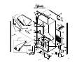
MARS PARTS SECTION ..................................................................................... Pages PS-1 – PS-42
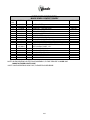
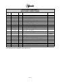
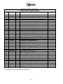
READING A PARTS LIST..................................................................................... Page PS-2
HARDWARE LIST ................................................................................................ Pages PS-3 – PS-5
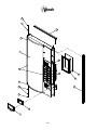
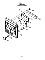
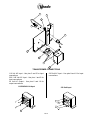
OUTER DOOR...................................................................................................... Pages PS-6 – PS-7
SELECTION PANEL ............................................................................................. Pages PS-8 – PS-9
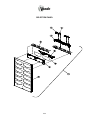
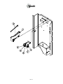
OUTER DOOR (INSIDE VIEW) ............................................................................ Pages PS-10 – PS-11
REFUND MOTOR ASSEMBLY ............................................................................ Pages PS-12 – PS-13
TC-2
COIN ENTRY ASSEMBLY ................................................................................... Pages PS-14 – PS-15
CONTROLLER ASSEMBLY ................................................................................. Pages PS-16 – PS -17
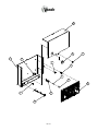
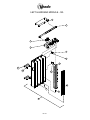
INNER DOOR ASSEMBLY................................................................................... Pages PS-18 – PS-19
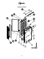
CABINET ASSEMBLY .......................................................................................... Pages PS-20 – PS-21
ELECTRONIC COMPONENTS ............................................................................ Pages PS-22 – PS-23
OPTIC ASSEMBLY............................................................................................... Pages PS-24 – PS-25
INTERNATIONAL AIR DAM ASSEMBLY ............................................................. Pages PS-26 – PS-27
BAR MODULES .................................................................................................... Pages PS-28 – PS-29
LEFT HAND BAR MODULE ................................................................................. Pages PS-30 – PS-31
BAG MODULE ...................................................................................................... Pages PS-32 – PS-33
UNIVERSAL MODULE ......................................................................................... Pages PS-34 – PS-35
REFRIGERATION ASSEMBLY ............................................................................ Pages PS-36 – PS-37
HARNESS QUICK REFERENCE GUIDE ............................................................. Page PS-38
LABELS, DECALS AND GRAPHICS.................................................................... Page PS-39
SUGGESTED SPARE PARTS ............................................................................. Pages PS-40 – PS-41
TROUBLESHOOTING ......................................................................................... Pages T-1 – T-11
VENDO WARRANTY............................................................................................ Page T-2
TROUBLESHOOTING GUIDE ............................................................................. Pages T-3 – T-8
PARTS, SALES, & SERVICE CENTERS OF VENDO/SANDEN COMPANY ...... Pages T-9 – T-10
TC-3
SAFETY
S-1
A COMMITMENT TO SAFETY
The Vendo Company is committed to safety in every aspect of our product design. Vendo is
committed to alerting every user to the possible dangers involved in improper handling or
maintenance of our equipment. The servicing of any electrical or mechanical device involves
potential hazards, both to those servicing the equipment and to users of the equipment.
These hazards can arise because of improper maintenance techniques. The purpose of this
manual is to alert everyone servicing Vendo equipment of potentially hazardous areas, and to
provide basic safety guidelines for proper maintenance.
This manual contains various warnings that should be carefully read to minimize the risk of
personal injury to service personnel. This manual also contains service information to insure
that proper methods are followed to avoid damaging the vendor or making it unsafe. It is also
important to understand these warnings are not exhaustive. Vendo could not possibly know,
evaluate, or advise of all of the conceivable ways in which service might be done. Nor can
Vendo predict all of the possible hazardous results. The safety precautions outlined in this
manual provide the basis for an effective safety program. Use these precautions, along with
the service manual, when installing or servicing the vendor.
We strongly recommend a similar commitment to safety by every servicing organization. Only
personnel properly trained in vendor servicing should have access to the interior of the
machine. This will minimize the potential hazards that are inherent in electrical and
mechanical devices. Vendo has no control over the machine once it leaves the premises. It is
the owner or lessor’s responsibility to maintain the vendor in a safe condition. See Section I of
this manual for proper installation procedures and refer to the appropriate service manual for
recommended maintenance procedures. If you have any questions, please contact the
Technical Services Department of the Vendo office nearest you. Refer to the listing at the
back of this manual.
SAFETY RULES
•
•
•
•
•
•
•
•
•
•
•
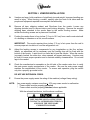
Read the Safety Manual before installation or service.
Test for proper grounding before installing to reduce the risk of electrical shock and fire.
Disconnect power cord from wall outlet before servicing or clearing product jams. The
vending mechanism can trap and pinch hands.
Use only fully trained service technicians for “Power On” servicing.
Remove any product prior to moving a vendor.
Use adequate equipment when moving a vendor.
Always wear eye protection, and protect your hands, face, and body when working near the
refrigeration system.
Use only authorized replacement parts.
Be aware of inherent dangers in rocking or tipping a vending machine.
Always turn power off before plugging or unplugging vendor to wall outlet.
S-2
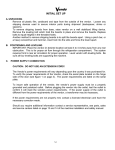
SECTION I: VENDOR INSTALLATION
A.
Vendors are large, bulky machines of significant size and weight. Improper handling can
result in injury. When moving a vendor, carefully plan the route to be taken and the
people and equipment required to accomplish the task safely.
B.
Remove all tape, shipping sealant, and Styrofoam from the vendor. Loosen any
shipping devices used to secure interior parts during shipping. Remove the wooden
shipping base, attached to the vendor base by the vendor leveling screws. Make
certain the leveling screws are in place and functional.
C.
Position the vendor three to four inches (7.6 cm to 10.2 cm) from a well-constructed wall
of a building or otherwise on a flat, smooth surface.
IMPORTANT: The vendor requires three inches (7.6 cm) of air space from the wall to
ensure proper air circulation to cool the refrigeration unit.
D.
Adjust the leveling screws to compensate for any irregularities on the floor surface.
Ideally, no adjustment will be necessary and the leveling legs will be flush with the
bottom of the vendor. A spirit level is a useful aid to level the vendor. When the vendor
is properly leveled, the outer door, when opened, will remain stationary. Vendors must
be level to insure proper operation and to maintain stability characteristics. Do not add
legs to the vendor.
E.
Check the manufacturer’s nameplate on the left side of the vendor outer door to verify
the main power supply requirements of the vendor. Be sure the main power supply
matches the requirements of the vendor. To ensure safe operation, plug the vendor
only into a properly grounded outlet.
DO NOT USE EXTENSION CORDS.
F.
Ensure the power supply meets the rating of the machine (voltage & amp rating).
NOTE:
Any power supply variance more than + 10% may cause vendor to malfunction.
* Power outlets must be properly grounded.
* Power outlets must be properly polarized, where applicable.
With the relevant test device, test the above conditions.
IF THE ABOVE CONDITIONS ARE NOT
MET FOR THE GIVEN OUTLET TYPE,
CONTACT A LICENSED ELECTRICIAN
AND HAVE THE NECESSARY
CORRECTIONS MADE.
S-3
SECTION I: VENDOR INSTALLATION (CONT’D)
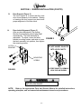
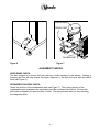
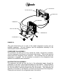
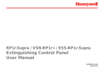
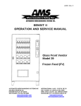
G.
Door Support (Figure 2)
The door support is to insure that the outer
door closes squarely to the cabinet. Raising
or lowering the door support can also insure
proper alignment of the door latch.
H.
Door Latch Alignment (Figure 3)
After any door adjustment, the floating
Quicker Lock assembly should align itself
automatically. The latch assembly is
adjustable. To adjust, loosen the latch
bracket mounting screws, and raise or lower
the latch assembly into position, then tighten
the mounting screws.
LATCH
BRACKET
FIGURE 2
DO NOT INSERT OBJECTS
INTO LOCK CAVITY.
2
1
MOUNTING
SCREW
TO FREE OBJECTS, REMOVE
LOCK CAP AS SHOWN
FIGURE 3
KEEP FINGER AND OTHER OBJECTS
OUT OF LOCK CAVITY.
NOTE: Refer to the appropriate Parts and Service Manual for detailed instructions,
operating principles, and recommended maintenance intervals and procedures.
S-4
SECTION II: ELECTRICAL HAZARDS
GENERAL
Vendo vending machines are provided with the appropriate power supply setting for your area.
All models are equipped with transformers, enabling the vending machine to operate on
different mains voltages. Refer to the appropriate Service Manual for details of transformers
operations.
The power sources are standard for both household and commercial lighting and appliances.
However, careless or improper handling of electrical circuits can result in injury or death.
Anyone installing, repairing, loading, opening, or otherwise servicing a vending machine
should be alerted to this point. Apply all of the normal precautions observed in handling
electrical circuits, such as:
•
•
•
•
•
•
A.
Refrigeration servicing to be performed by qualified personnel only.
Unplug the vendor or move power switch to off position before servicing or clearing product
jams.
Replace electrical cords if there is any evidence of fraying or other damage.
Keep all protective covers and ground wires in place.
Plug equipment into outlets that are properly polarized, where applicable, and protected
with fuses or circuit breakers.
All electrical connections must be dry and free of moisture before applying power.
Grounding Systems
Vendo vending machines are provided with the appropriate service cord for the power
supply in your area. The service cord will connect to the matching electrical outlet.
Always ensure that the outlet to be used is properly grounded, and polarized where
applicable, before plugging in the vendor.
ALWAYS TEST TO VERIFY PROPER
GROUNDING PRIOR TO
INSTALLATION IN ORDER TO
REDUCE THE RISK OF
ELECTRICAL SHOCK AND FIRE
The electrical grounding system also includes the bonding of all metal components within the
vendor. This involves a system of bonding wires identified by green or green and yellow
marking. The system uses serrated head screws, lock washers, and star washers to insure
the electrical connection between parts. Maintenance of vending equipment may involve
disassembly. Include the above items when reassembling, even if the vending machine may
appear to function normally without them. Omitting any of these items can compromise a link
in the grounding system. See the appropriate Service Manual or kit instructions for
components and assembly instructions.
S-5
SECTION II: ELECTRICAL HAZARDS (CONT’D)
B.
Servicing with “Power Off”
For maximum safety, unplug the service cord from the wall outlet before opening the
vendor door. This will remove power from the equipment and avoid electrical and
mechanical hazards. Service personnel should remain aware of possible hazards from
hot components even though electrical power is off. See the appropriate sections of
this manual for further information.
C.
Servicing with “Power On”
Some service situations may require access with power on. Only fully qualified service
technicians should perform power-on servicing. Particular caution is required in
servicing assemblies that combine electrical power and mechanical movement.
Sudden movement, to escape mechanical action, can result in contact with live circuits
and vice versa. It is therefore doubly important to maintain maximum clearances from
both moving parts and live circuits when servicing.
ONLY FULLY TRAINED PERSONNEL
SHOULD ACCOMPLISH “POWER-ON”
SERVICING. SUCH SERVICE BY
UNQUALIFIED INDIVIDUALS CAN BE
DANGEROUS.
D.
Lithium Battery
This machine contains a Lithium Battery mounted on the VMC board. Always properly
dispose of used batteries. DO NOT attempt to recharge battery. DO NOT throw battery
into fire or expose to heat.
EXPLOSION HAZARD. ALWAYS
PROPERLY DISPOSE OF USED
BATTERIES. DO NOT HEAT OR THROW
INTO FIRE. SERIOUS INJURY OR
DEATH MAY RESULT.
S-6
SECTION III: MECHANICAL HAZARDS
A.
Servicing of Moving Parts and Assemblies
When servicing assemblies involving moving parts, use extreme caution!! Keep
fingers, hands, loose clothing, hair, tools and other foreign material clear of entrapment.
As noted before under the Electrical Hazards section, “Power On” qualified personnel
should only perform servicing. Refer to and heed the warnings noted in Electrical
Hazards section. These warnings refer to the potential hazards associated with
electrical power and moving parts. Always maintain maximum clearances from
electrical and moving parts.
Always reinstall protective covers and guards when reassembling equipment.
THIS VENDING MACHINE INCLUDES
MECHANICAL EQUIPMENT WHICH CAN
BE HAZARDOUS IF IMPROPERLY
HANDLED OR SERVICED. USE CAUTION
AND CONSULT THE VENDO SAFETY
MANUAL AND THE VENDO SERVICE
MANUAL FOR ADDITIONAL SAFETY
INFORMATION.
RISK OF ENTRAPMENT!
RISK OF ELECTRICAL!
S-7
SECTION IV: REFRIGERATION HAZARDS
GENERAL
Refrigeration systems involve both electrical power and mechanical action. These systems
may present any of the potential dangers shown in the sections on Electrical and Mechanical
Hazards contained in this manual.
A.
Compressed Refrigerant
Refrigeration systems involve the compression and evaporation of gases. The
pressures contained represent a potential hazard if suddenly released in confined
areas. Caution is required when performing maintenance tests or repairs. Trained
personnel who are familiar with the systems and pressures involved should do all
testing of sealed refrigeration systems.
B.
Physical Protection
The accidental release of refrigerant gases can result in physical injuries. Always wear
protective glasses and protect your hands, face, and body when working near the
refrigeration system.
ALWAYS WEAR EYE PROTECTION
AND PROTECT YOUR HANDS, FACE,
AND BODY WHEN WORKING NEAR
THE REFRIGERATION SYSTEM.
S-8
SECTION V: TEMPERATURE HAZARDS
GENERAL
Maintenance personnel should be alert to the potential hazards from hot metal surfaces. High
temperatures may be present throughout the refrigeration system although electrical power
has been removed.
SECTION VI: SUBSTITUTIONS AND MODIFICATIONS
GENERAL
Unauthorized changes, or the substitution of unauthorized parts, can compromise the
equipment designs. This can result in unsafe conditions for either the service personnel or the
equipment users. Always refer to the appropriate Parts and Service Manual for replacement
parts and maintenance instructions. If questions arise, contact the Technical Services
Department of the Vendo office in your area. (See pages T–10 and T-11.)
When servicing the vending machine, always reassemble all components to their original
location and position. Maintain the correct routing for tubing, electrical wiring, etc. Replace all
clamps, brackets, and guides to their original locations. Replace all tubing, sleeving, insulating
material, and protective covers to their original condition.
VENDO EQUIPMENT HAS BEEN PROVIDED
WITH APPROPRIATE PROTECTIVE
DEVICES TO PROTECT AGAINST THE
POSSIBILITY OF OVERHEATING AND FIRE,
AS A RESULT OF EQUIPMENT OR
COMPONENT FAILURES. SUBSTITUTION,
MODIFICATION, OR BYPASSING OF SUCH
PROTECTIVE DEVICES CAN CREATE
DANGEROUS CONDITIONS. PROTECTIVE
CIRCUITS SHOULD NEVER BE BYPASSED,
AND FAILED PROTECTIVE DEVICES MUST
BE REPLACED ONLY WITH FACTORYAUTHORIZED PARTS.
A.
Service Cord Replacement
Vendo vending machines are furnished with unique power supply cords. If replacement
becomes necessary, consult the Parts Section and order the correct replacement cord
for the model of vending machine in question. Do not use substitute replacement cords.
Only authorized service personnel with appropriate training should replace the vending
machine service cord. If a question should arise concerning which service cord to
order, contact the Technical Services Department of the Vendo office in your area for
assistance.
S-9
SECTION VI: SUBSTITUTIONS AND MODIFICATIONS (CONT’D)
THIS APPLIANCE MUST BE EARTHED
IMPORTANT
The wires in the main leads are colored in accordance with the following code:
110V/120V
Green
White
Black
220V/240V
Green and Yellow ............................ Earth
Blue .................................................. Neutral
Brown ............................................... Live
S-10
SECTION VII: CONSUMER SAFETY WARNING
CRUSH HAZARD
VENDOR CAN BE OVERTURNED IF
SUFFICIENT FORCE IS APPLIED, AND MAY
RESULT IN SERIOUS INJURY OR DEATH.
GENERAL
There have been incidents, including fatalities, when vending machines have been vandalized
by being pulled over in an attempt to obtain free product or money.
To warn of the danger involved in tipping, shaking, or rocking the vending machine, a decal
has been designed to be affixed to vending machines. (One such decal is supplied with the
vending machine.) Vendo will supply sufficient decals to be placed on all machines, on
request. Should you require additional information, contact a service representative. See
parts, sales and service centers listed on page T-10 and T-11.
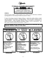
THE FOLLOWING DECAL SHOULD BE PLACED IN A POSITION ON THE
VENDOR CONTROL PANEL AT EYE LEVEL.
WARNING
Never rock or tilt.
Machine can fall over
and cause serious
injury or death.
Vending machine will
not dispense free
product.
MISE EN
GARDE
Ne jamais secouer
ou incliner.
Le distributeur peut
se renverser et causer
des blessures graves
ou la morte.
Cette machine ne
distribue pas de
produits gratuitement.
389611-1A
389611A
ENGLISH
FRENCH
S-11
AVISO
Nunca voltie o incline
esta maquina.
Puede caer sobre usted
y cauzarle heridas
graves o matarle.
Esta Vendomatica no
provee producto gratis.
389611-2A
SPANISH
NOTES
S-12
GENERAL INFORMATION
G-1
G-2
GENERAL INFORMATION
This manual contains programming, operation, and complete parts and electrical wiring
diagrams.
The Mars controller has a microprocessor that will permit pricing per selection from 0.00 to
99.99. This machine also has space-to-sales programming.
Specifications:
MARS
MODEL
12
SELECTIONS
DIMENSIONS (HEIGHT X WIDTH X DEPTH)
72” x 39“ x 30” (183cm x 99 cm x 76 cm)
SERIES 2000
VENDING PRODUCT CAPACITY:
BAR MODULES:
BAG MODULE:
UNIVERSAL MODULE:
46 BARS PER COL.
39 BAGS PER COL.
21 BAGS PER COL.
4 COL. PER MODULE
3 COL. PER MODULE
3 COL. PER MODULE
TOTAL:184 BARS PER
TOTAL:117 BAGS PER
TOTAL:63 BAGS PER
MODULE
MODULE
MODULE
685 POUNDS (311 kg)
SHIPPING WEIGHT
115v 60 Hz.
220v 50 Hz
240v 50Hz
OPERATION VOLTAGE
(U.S.)
(Int’l)
(UK, Australia)
10
AMP. RATING
115v 60Hz.
220v 50 Hz
240v 50Hz
REFRIGERATION
(U.S.)
(Int’l)
(UK,
Australia)
VOLTAGE
*Dimensions and shipping weight will vary slightly due to manufacturing tolerances, shipping
boards, and whether or not coinage is installed.
G-3
INITIAL SET UP
A.
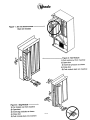
UNPACKING
Remove all plastic film, cardboard, and tape from the outside of the vendor. Loosen
any shipping devices used to secure interior parts during shipment.
To remove shipping boards from base, raise vendor on a well-stabilized lifting device.
Remove the leveling bolts, which hold the boards in place and remove the boards.
Replace bolts to equal heights in the threaded holes.
Another method to remove shipping boards is to split the boards apart. Using a pinch
bar, or a heavy screwdriver and hammer, insert tool into the slots and force the board
apart.
B. POSITIONING AND LEVELING
IMPORTANT: PLACE THE VENDOR (IN DESIRED LOCATION) AT LEAST 3 TO 4
INCHES or 8 TO 10 CM AWAY FROM ANY REAR OBSTRUCTION. This is for proper
airflow through the refrigeration compartment. The system requires front to rear air
circulation for proper operation. Level vendor with leveling bolts. Be sure all four
leveling bolts are supporting the machine.
C.
POWER SUPPLY CONNECTION
DO NOT USE AN EXTENSION CORD
The vendor’s power requirements will vary depending upon the country it was
purchased for. To verify the power requirements of the vendor, check the serial plate
located on the hinge side of the door (see Figure 4 on page G-4). The power
requirements are listed on the serial plate.
To insure safe operation of the vendor, the vendor’s power supply must be a properly
grounded and polarized outlet. Before plugging the vendor into the outlet, test the outlet
to confirm it will meet the vendor’s power requirements. If the power supply of the outlet
is different from the power requirements of the vendor, different settings on the
transformer may be necessary.
If the power requirements are not properly met, contact a licensed electrician and have
the necessary correction made.
Should you require additional information, contact a service representative. See the
parts, sales and service centers listed in the back of this manual.
G-4
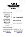
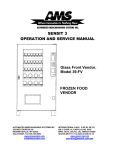
INTRODUCTION AND MODEL IDENTIFICATION
Example:
APPROVED FOR OUTDOOR USE
MODEL
BASIC
UNIT
SERIAL NO.
CHARGE
Lot Code: YYMMDD
LR 13085
OZ. R-134a
AMPS
MIN. TEST PRESSURE APPLIED - PSI
HIGH SIDE 235
LOW SIDE 140
endo
R
239L
R
THE VENDO COMPANY FRESNO, CA.
VENDING MACHINE
REFRIGERATED
115v
50/60
1
VOLT
CYCLE
PHASE
POWER REQUIREMENTS
FIGURE 4
NOTE: The Model number of the vending machine is located on the top, left hand corner of the
serial plate. Do Not use the “BASIC UNIT” number. The BASIC number is the cabinet
size, which is used on a number of different machines. A typical model number could read
“786502004”. The 786 is the model number, and the 004 tells what options are included.
G-5
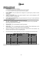
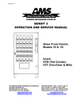
LABEL INSTALLATION
FLAVOR LABELS: Flavor labels are installed from inside the outer door. Open the vendor
door and swing the inner door away, to gain access to the reverse side of the control panel.
Open the coinage door. The flavor labels slide into carrier clips on the back of each flavor
window (Figure 5).
NOTE: Make sure the correct flavor label has been installed for each selection. This vendor
can be programmed to link selection buttons to vend modules in a variety of different
configurations. Refer to the section on electronic-control programming for detail on the vendor
selection set up.
FLAVOR
LABEL
BUTTON ASSY
Figure 5
G-6
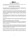
COMPRESSOR
DRAIN TUBE
PAN
FAN BRACKET
Figure 6
Figure 7
ALIGNMENT CHECKS
DOOR RAMP CHECK:
The door support is to ensure that the outer door closes squarely to the cabinet. Raising or
lowering the door will help ensure the proper alignment of the door lock stud and the cabinet
latch (see Figure 6).
REFRIGERATION AREA CHECK:
Check the position of the condensation pan (see Figure 7). The correct position of the
condensation pan is between the compressor and the condenser fan bracket. Be sure the
drain tube is clipped to the pan and free of kinks. The trap prevents warm air from reaching
the evaporator area.
G-7
VENDOR TEMPERATURE CONTROL SETTING
The cabinet temperature is regulated by the temperature control, located on the left side of the
evaporator. Before adjusting the control, be sure the refrigeration system is working properly.
Check that the condenser and evaporator fans run freely and do not make excessive noise,
which might indicate an obstruction to the fan blade. The evaporator and condenser grills
should be free from debris. In addition, check the condition of the door gasket, to ensure a
proper seal on the cabinet.
When the air temperature at the feeler bulb reaches 65°F (18°C), the refrigeration system
should cycle on. To lower the cabinet temperature, turn the temperature control adjustment
screw CLOCKWISE. To raise the cabinet temperature, turn the adjustment screw COUNTERCLOCKWISE. The cabinet temperature will change 6 degrees for every 1/4 turn of the
adjustment screw (Figure 8).
To ensure correct temperature control operation, it is essential that the control feeler bulb be
positioned in the air flow from the evaporator, and not resting against any metal surfaces
(other than the retaining clip), which will give a misleading reading to the control. This feeler
bulb should not require adjustment unless the refrigeration system has been removed for
servicing (Figure 9).
CAPILLARY
TUBE
CO
L
D
E
R
CLIP
TEMPERATURE
CONTROL
TEMPERATURE
CONTROL
Figure 8
Figure 9
G-8
ELECTRO-MECHANICAL FUNCTIONAL DESCRIPTION
VEND MODULE CONFIGURATION AND OPERATION:
The Mars Vendo Confectionery vendor is specially designed to dispense chilled bar-type and
bag-type products, as specified by Mars.
The vendor cabinet is divided into two
compartments; the lower portion is open to the ambient environment, and houses the majority
of the refrigeration system components. The remainder of the cabinet is refrigerated to
preserve the vended product.
The vended product, in bar, bag, or combo form, is dispensed from vend modules mounted in
the refrigerated cabinet. There are spaces for up to five vend modules in the cabinet. The use
of five modules however, requires a full 180° swing of the outer door. The modules will always
be one of four varieties:
A) Right-Hand Bar Module
B) Left-Hand Bar Module
C) Bag Module
D) Bag Combo Module
There are two types of bar modules, because of the way these modules are loaded. Bar
product is loaded into only one side of the module as it is pulled out for loading. Therefore, a
right-hand bar module is always installed in the first position at the right side of the cabinet, so
that full access to the module chambers is available. The left-hand bar modules can be
situated in any of the remaining positions in the cabinet.
The bag modules, on the other hand, are loaded from both sides when pulled out for loading.
Therefore, there is only one version of the bag module. Due to the requirement for access to
both sides of the module during loading, these modules can only be installed in the three
center positions.
The Combos module is a right hand module and therefore can only reside in the first position
at the right side of the cabinet.
Each vend module consists of a steel housing with compartments, or columns, segregated by
steel partitions. On bar modules, there will always be four chambers, or columns per module.
On bag modules including Combos modules, however, due to the larger size of bag product,
there are only three chambers, or columns, per module. Each module chamber, or column,
has an access door, full-height, on the column. Bar modules have one door per column; bag
modules have two doors per column--one on either side of the module for each column. The
Combos module has one steel door over all three columns. In each case, these doors keep
the product in place within each column of the module. Each module is hung from a support
channel mounted to the cabinet ceiling, and suspended between a pair of sliding rails, which
allows the module to be pulled forward for loading.
G-9
ELECTRO-MECHANICAL FUNCTIONAL DESCRIPTION (CONTINUED)
The product is stored and dispensed by a motor-driven plastic product helix, except in the case
of the Combos module, where the helix is a powder coated wire helix. The bar-product helix,
bag-product helix, and Combos product helix are different part numbers, as both the diameter
and pitch are different. The helix, in the case of the bar and bag, is driven by the same part
number vend motor. The Combos helix is driven by its own motor that is different from the bag
and bar motors. The vend motors are mounted to a steel support channel at the top of each
module, and are connected by a module harness to the cabinet harness. The vend motors are
connected to the electronic controller in such a way that any combination of vend motors can be
assigned to an individual selection button. This feature allows space-to-sales programming of
the vendor’s column to the selection buttons, to maximize the use of space for prime product
versus slower-moving products.
PRODUCT LOADING:
Check the machine configuration for bar and bag products before loading. All product modules
should have labels indicating exactly which products must be loaded.
Pull each product out such that products can be loaded into the machine. Only one product
module must be loaded at a time. Refer to page G-11.
1)
2)
Bar products are loaded from one side of the product module only.
Bag products are loaded from each side of the product module, as the module has 2
doors for full access during loading.
No gaps should be left between products. It is essential that ALL spaces are filled.
Ensure that the product module door is closed after loading.
NOTE: Bag product loading
1) Ensure that seam is facing upwards when loaded.
2) Ensure that the product is evenly distributed in the bag.
NOTE: Bar product loading
1) Ensure that seam is facing upwards when loaded.
2) Ensure that the product is evenly distributed in the bar.
G-10
See Page G-11 for details.
THE VEND CYCLE:
In order to initiate a vend, the customer must first set up a credit. A credit is registered by
inserting coins into the coin slot (and into the coin mechanism), by inserting a bill into the bill
validator (if available), or by inserting a debit card into the debit-card reader (if available).
Once a credit is established equal to or in excess of the lowest product price, the customer is
allowed to make a selection. By pressing the selection button of their choice, a signal is sent
to the electronic controller which, in turn, feeds power to the vendor column(s) assigned to that
selection.
Product is vended when a vend motor assigned to that selection is energized by a circuit from
the electronic controller. The motor rotates its product helix, and drops the bottom product out
of the bottom of the helix. The product falls freely onto the product chute.
As the product passes down the product chute, it passes through the vend detection system,
where optical sensors detect the passage of the product on its way to the product hopper. The
passage of product through the vend detection sensors signals the electronic controller, which
then performs a variety of functions. The vended product ends up in the product hopper and is
removed by the customer as they push open the vend door. (See pages PR3 – PR23 for
further electronic controller details.)
G-11
G-12
REFRIGERATION SYSTEM - FUNCTIONAL DESCRIPTION
BASIC REFRIGERATION PRINCIPLES:
A refrigeration system is principally involved in the process of transferring heat. Heat is
removed from the vending product area of the cabinet, and is transferred to the condenser,
where it is dissipated. With vending equipment, large quantities of heat must be transferred
economically and efficiently in a continuous fashion, without loss of refrigeration gas, over a
long period of time. The most common type of refrigeration system in vending is the vapor
compression, or simple compression cycle system. This system consists primarily of three
elements: a compressor, an evaporator, and a condenser, joined together as a “sealed
system”.
In the vapor compression system, there are two pressures present: Low, evaporating
pressure and high, condensing pressure. The refrigerant gas acts as the transport medium in
which heat is transferred from the evaporator to the condenser, where heat is dissipated into
ambient air. A change of state occurs as the refrigerant changes from liquid to vapor and back
to liquid again, allowing the refrigerant to absorb and discharge large quantities of heat in an
efficient manner.
The basic vapor compression cycle occurs as follows: In the evaporator, the refrigerant boils
(evaporates to vapor), at a temperature sufficiently low enough to absorb heat from the cabinet
space being cooled. The pressure maintained in the evaporator controls the boiling
temperature. The higher the pressure, the higher the boiling point. The compressor removes
the vapor via suction lines from the evaporator at a rate sufficiently rapid to help maintain the
desired pressure. The compressor takes the low-pressure vapor and compresses it,
increasing both the pressure and temperature of the vapor. This hot, high-pressure gas is
forced out of the compressor discharge valve and into the condenser. Upon reaching the
condenser, the refrigerant dissipates its heat and condenses into liquid. This liquid, in turn,
flows from the condenser back to the evaporator to repeat the cycle.
VENDO REFRIGERATION SYSTEM OPERATION:
The general cycle described above occurs within the refrigeration system fitted in Vendo
equipment. A more detail explanation of the function of the various components in the system
follows.
As the temperature within the cabinet increases, the liquid contained in the temperature-control
feeler bulb also rises in temperature, and, in doing so, expands. This expansion increases the
pressure against the temperature control bellows, and actuates the temperature control switch.
This switch directs power to the compressor and condenser fan motor. The compressor pulls
low pressure refrigerant vapor from the evaporator and compresses it, increasing both its
temperature and pressure.
This high-temperature/pressure vapor is expelled to the
condenser, where the vapor sheds its excess heat, as drawn off by the airflow created by the
condenser fan through the condenser fins. More specifically, the condenser fan pulls air
through the condenser, removing heat from the refrigerant vapor in the condenser coils.
REFRIGERATION SYSTEM - FUNCTIONAL DESCRIPTION (CONTINUED)
G-13
The cooled gas in the condenser turns to liquid, which is pumped via pressure from the
compressor through the drier, which removes any water and particles from the liquid
refrigerant. This liquid is then forced through the small-diameter capillary tube, which acts like
a throttle for the system, controlling the flow rate of the liquid refrigerant into the evaporator.
Airflow is circulated throughout the cabinet by the evaporator fan, which pulls airflow through
the coils and fins of the evaporator. Any excess heat present in the airflow is drawn off by the
liquid refrigerant, which evaporates, and is, in turn, pulled via the compressor. The falling
temperature in the cabinet eventually cools the liquid in the temperature control feeler bulb,
condensing the liquid inside, reducing its pressure, which releases the pressure against the
temperature control bellows. This reduction deactuates the switch inside, cutting off power to
the compressor and condenser fan motor.
HEATING SYSTEM - FUNCTIONAL DESCRIPTION
VENDO HEATING SYSTEM OPERATION:
This vendor is also equipped with a heating element for cold weather environments. This
system consists of a simple 150W, 230V or 115V heating element located just behind the
evaporator fan air ducting. This unit is controlled by its own thermostat and is activated when
temperatures are in danger of freezing the product.
HEATING ELEMENT CAN CAUSE
MINOR BURNS TO YOUR HANDS AND
FINGERS IF TOUCHED WHEN
ELEMENT HAS BEEN ENERGIZED FOR
ANY LENGTH OF TIME.
G-14
VENDOR ELECTRONIC CONTROLLER
DESCRIPTION:
The Mars Vendo Confectionery machine comes equipped with an integral electronic-control
system, which manages the vendor’s mechanical functions, monitors the vend system for
failures, controls the vendor’s coin mechanism, drives the vendor’s scrolling display, and keeps
track of sales data, among other functions. The control systems consist of the following major
components:
•
•
•
•
•
•
•
Electronic Control PC Board
Harnessing
Scrolling Display
Transformer
Reset Switch
Vend Detection System
Coin Mechanism
These components work together to jointly control the vendor’s functions. The control system
is programmed with the following capabilities:
•
•
•
•
•
•
•
Space-to-Sales Programming
Sales Data Storage
Data Retrieval via DEX/UCS Plug or Optical Datalink
Self-Diagnostics for the Vend Mechanism
Multi-Pricing
Multi-Vend
Multi-Lingual and Personal-Message Display Programming
In order to begin programming the electronic controller, it is necessary to understand the
purpose and location of each of the major components listed above.
Electronic Control PC Board: Located on the outer door, inside a protective housing, the
electronic controller is the heart of the vendor control system. This board contains all the
microprocessors, memory microchip, and other electronic devices needed to control the
functions of the vendor. Also located on the PC board is a small push-button switch, the mode
switch, whose purpose is explained in the electronic controller programming section that
follows. This switch is accessible through a grommeted hole in the electronic controller
housing cover.
Harnessing: Connected to the electronic control PC board are a series of harnesses that
supply power to the control board, and distribute power to the various systems within the
vendor. The harnesses are all keyed in such a way that they cannot be installed on the wrong
set of pins, or misconnected on their correct PC board pins (refer to the Electrical Servicing
section for harness connection detail).
G-15
VENDOR ELECTRONIC CONTROLLER (CONTINUED)
Scrolling Display: Located on the control panel, above the selection button and coin-insert
plate on the front of the vendor, is a scrolling, 20-character display. This display provides
consumer messages such as credit-level established and selections out-of-order during a
candy sale, allows for interactive feedback during programming, and faultfinding when
servicing. The display can be programmed to display messages in eight different languages.
In addition, the display can be programmed to display a custom scrolling message.
Transformer: Each vendor is equipped with a step-down transformer, to drop the input
voltage available at the location to 24 volts, for use by the electronic control board, vend motor,
and display. The transformer is located at the rear of the cabinet base, beneath a protective
cover (refer to the Electrical Servicing section for details on transformer connections).
Reset Switch: Located on the vend-chute support plate, beneath the vend chute in the
cabinet, there are two switches mounted in the support plate. The push-button switch with the
unshielded plunger is the reset switch. When activated, this switch signals to the electronic
controller that the vendor outer door has been closed, indicating the end of service duties, and
resets the controller. (The other switch in this pair, with a shielded switch plunger, is the doorpower switch--its purpose is to isolate the door circuits when the outer door is opened for
service.)
Vend Detector System: Located on either side of the discharge portion of the vend chute in
the vendor cabinet is the vend detector system. It consists of two PC boards, an emitter
board, and a detector board. These two boards scan across the vend chute, to detect vended
product. This information is used by the electronic controller to determine whether a product
has been delivered. If it has been delivered, the controller can instruct the coin mechanism to
cancel the customer’s credit, pay out any change due to the customer, and update the sales
data memory fields. If no product is detected as delivered, the electronic controller will run the
selected product’s vend motor again, to dispense another product.
Coin Mechanism/Bill Validator: The coin mechanism is connected to the electronic
controller in a master/slave relationship, with the controller serving as master. The coin
mechanism validates incoming coins, pays out change as required, and transfers sales data to
the electronic controller. The Mars Vendo Confectionery machine electronic controller is
programmed to accept a variety of different Mars coin mechanisms, and Vendo provides the
appropriate harnessing to interface with these units (refer to pages 90 - 91 for harness details).
G-16
NOTES
G-17
PROGRAMMING SECTION
PR-1
MARS PROGRAMMING
MODE 1: OPERATION MODE
Upon entering the operation mode, the vendor will automatically check all of the motors
assigned to selection buttons to ensure they are in the home position. The controller will
attempt to home any motors found to be out of position. If the controller detects a motor out of
the home position, after a predetermined time, that motor will be recorded as “bad” and no
further attempts will be made to run that motor during operation.
During operation mode, the vendor display will scroll through the programmed user’s
messages. The vendor display will not scroll through these messages if the vendor is totally
sold out, all of the vend motors are out of service, or if the vend detector is activated for more
than five seconds.
When a selection is made, the controller will run the assigned vend motor. The product auger
attached to that motor will rotate, allowing a product to fall free from the vend mechanism, onto
the product chute. The product slides down the product chute and, in doing so, passes
through the vend detection system, as it makes its way to the vend hopper. The vend
detection system signals the controller board that a vend has occurred. The controller, in turn,
deducts the product price from the customer’s credit, pays out any change that may be owed,
and updates the sales data in memory. The display will flash the message “PLEASE
REMOVE YOUR PRODUCT.”
The controller is designed to operate with a number of different coin mechanisms or bill
validators and has the ability to recognize which type of coin mechanism is installed.
ENTERING OPERATION MODE
This mode is the normal operating mode of the machine for receiving credit, paying change,
and dispensing product to the customer.
The Operation Mode is entered whenever one of the following occurs:
a) The mode switch is depressed once from the Entry Code Mode if the correct entry
code has not been keyed in, or the mode switch is depressed once from the
last machine programming mode.
b) The door is closed (causing the open/close signal door switch to activate).
c) No operation for five minutes.
d) A coin, bill, or debit card has been detected.
Whenever the Operation Mode is entered, all of the assigned motors will be checked to see if
they are in their home position. The controller system will try to re-home any motors that are
not in their home positions.
PR-2
In Operation Mode, the programmable user message is displayed during idle time unless all
product is sold out in the machine, all the columns are either bad or unassigned, or if the IR
vend detect beam is broken for longer than 5 seconds.
In the case of all columns sold out, the display will indicate “Sold Out”.
In the case of all columns bad or not assigned, or the infrared (IR) beam broken, the
display will indicate “Out of Order”.
If the machine is configured appropriately, the reason for the out of order condition, will
be appended to the "Out of Order" message. The following messages are appended
(only 1 append at a time):
Bad beam -If there's a problem with the vend detect beam
Bad motors-If all assigned motors are bad
No motors -If all motors are unassigned
No cash -If some prices are 0.00 and no monetary peripheral is attached.
“Make Another Selection” - Product assigned to that selection is sold-out and/or there
are inoperable product motors, the blocker has been activated for product selected or
the selection has no columns assigned to it.
“Check Selection Price” - Not enough credit has been established to vend the
selected product. Additional credit can be established, or escrow return can be
requested to return credit (if allowed by force vend option). For MDB interfaces, the
"Use Correct Change" message will be followed by "Selection Price Is - ".
"Selection Price Is" - Not enough credit has been established to vend the selected
product. Additional credit can be established or escrow return can be requested.
“Use Correct Change” - The system is unable to make changes for the selection
requested. Escrow return can be requested and will return credit on a coin-for-coin
basis (if allowed by the force vend option).
A vend will occur when product has been detected by the vend sensing circuit. At that
time product price will be deducted from the credit, and change (if any), will be returned
depending on the multi-vend option.
When a vend occurs, the display will scroll the message “Please Remove Your
Product”.
PR-3
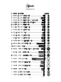
SWITCH
LAYOUT
1
2
3
4
5
6
7
8
9
10
11
12
MODE #2: SERVICE MODE
ENTERING SERVICE MODE
The Service Mode is entered when the door is opened and the mode switch is depressed
once. If there are no bad motors upon entering the Service Mode, the display will show "
Setup / Tube Control ".
If there are any bad motors upon entering Service Mode, the display will continuously display
all of the bad motors by column number for approximately two seconds before proceeding to
the next.
For Example: If A1 is bad, then the display will scroll “Bad Column A1”.
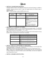
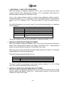
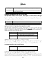
SWITCH #1 (CASH HANDLING MODE)
Pressing selection switch 1 of the vendor will determine the four different modes of cash
handling. Pressing selection switch 1 again will toggle the different types of cash
handling.
Note: The type of cash handling does not apply to executive interface.
DISPLAY
FORCE VEND
CASH
HANDLING
MODE
Force Vend
FORCE BILL or
FORCE COIN
Force Bill/Coin
CHANGE
Change Machine
NEUTRAL
Neutral
PR-4
DESCRIPTION
No escrows return unless product
selected is sold out.
Bill or high value coin is inserted
and accepted.
A selection must be made.
Bill or high value coin is inserted
and accepted.
Escrow return will return coins
with no vend transaction.
The first bill is held in escrow.
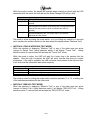
SWITCH #2 (CHANGE HANDLING MODE)
Pressing selection switch 2 will determine whether the multi-vend feature is enabled or
disabled. Pressing selection switch 2 again will toggle between the different types of
change handling.
Note: Change handling is used with MDB interface only.
DISPLAY
NORM VEND
MULTI VEND
CHANGE HANDLING
MODE
Regular Vend
Multivend
DESCRIPTION
Change is paid out after the vend
sensor detects the delivery of the
product.
Change due is held and
displayed, allowing for additional
purchases.
Change is returned when escrow
return is requested or 20 seconds
have elapsed.
Note:
Forced Vend is disabled when
the controller is in multivend.
SWITCHES 3, 4, 5, 6 (COIN PAY-OUT MODE)
Pressing selection switches 3, 4, 5 or 6 will enter the coin payout mode. The controller
system recognizes selection switches 3 thru 6. By pressing any of the above switches,
the controller will pay out accordingly (.5, .10, .25 etc.).
Note: Button 6 will only work for four-tube coin changers and the denomination will vary
by the country for which the coin mechanism is interfaced.
SWITCH #
3
4
5
6
FUNCTION
Dispenses coin from the tube associated with the
1st/lowest value coin (typically nickels in the USA)
Dispenses coin from the tube associated with the
2nd/lowest value coin (typically dimes in the USA)
Dispenses coin from the tube associated with the
3rd/lowest value coin (typically quarters in the
USA)
Dispenses coin from the tube associated with the
4th/lowest value coin (typically dollar coins in the
USA)
SWITCH 7 (DISPLAY OF UNASSIGNED COLUMNS MODE)
By pressing selection switch 7, the controller will cause the display to scroll through all the
unassigned columns. For Example: “Column A1”.
When all the columns have been displayed, the display will show “Setup/Tube Control”.
Note: If there are no unassigned columns, then the display will show “No Unassigned”
for approximately two seconds, followed by two audible beeps, and then the display will
show “Setup/Tube Control”.
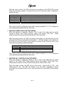
SWITCH 8 (COIN MECH SPECIFICATION)
PR-5
Pressing selection switch 8 will display the present type of Executive Coin Mech, which is
specified for the machine. Continued depressions of selection switch 8 toggle between
the two different types of mechs.
Note: If MDB mech interface is used, selection switch 8 can still be used to specify a
type of Executive Mech, but the setting will have no affect on the performance of the
machine.
If the Executive interface is used, it is critical to have the coin mech and VMC set to same
configuration (either both at normal mode, or both in the Price Holding / Price Display
Mode).
Displays
Executive
Executive PH/PD
Description
Specifies an Executive mech, where the prices are
stored in the VMC
Specifies an Executive mech with PH (Price Holding) and
PD (Price Display). With this type of mech, the prices are
held within the coin mech.
SWITCH 9 (CASH COUNTER DISPLAY MODE)
Pressing selection switch 9 will cause the display to show the last known value of the coin
mech tube inventory ("Invxxx.xxx"). In that mode, the operator is allowed to deposit any
coin into the coin changer acceptor when the coin’s tube is not full. The tube inventory
level will be displayed after each coin is accepted.
Note: This status is available with MDB coin mechs only. Executive interface provides
this information within the mechanism itself and cannot be accessed, and the display will
show "Invooo.ooo".
SWITCH # 10 (SINGLE / MULTI PRICE SELECTION MODE)
Pressing selection switch 10 will display the present configuration of the machine (single
vs. multi price). Continued depressions of the switch toggle between the two different
modes.
Display Mode
Single Price
Multi Price
Description
All items are sold at the prices assigned to selection #1
All items are sold at the prices specified for each selection
SWITCH # 11 (INC/DEC OVERPAY VALUE MODE)
Pressing selection switch 11 will display:
Overpay xx.xx
where xx is the max overpay amount
While the above message is displayed, depressing selection switch 11 will increase the
amount of overpay. Depressing the switch a second time will decrease the amount.
PR-6
SWITCH # 12 (MYSTERY VEND MODE)
Pressing selection switch 12 will display the present configuration of the machine (Mystery
Vend Off vs. On). Continued depressions of the switch toggle between the two different
modes.
Displays
Mystery Vend On
Mystery Vend Off
Description
The motor assigned to selection #12, will be
randomly selecting from #12’s STS setting
There is no special processing for Selection #12
MODE #3: SET PRICE MODE
ENTERING SET PRICE MODE
By pressing the mode switch twice will enter the Set Price Mode. You may also enter the Set
Price Mode by pressing the mode switch once from the Service Mode. Upon entry, the words
"Set Price" will appear on the display.
Depressing a selection switch once displays the present price of the selected product.
Depressing the same selection switch a second time increases the price in base unit
increments at the rate of approximately one base unit every half second for 5 seconds. After 5
seconds, the rate changes to one base unit every twentieth of a second.
Depressing the same selection switch a third time decreases the price in base unit decrements
at a rate of approximately one base unit every half second for 5 seconds. After 5 seconds, the
rate changes to one base unit every twentieth of a second.
Continued depressing of the same selection switch alternates between incrementing and
decrementing the price.
A zero price enables that selection to be free vended. Note: if an Executive mech in non
PRICE HOLDING/PRICE DISPLAY mode is used, the user must put in a coin.
MODE #4: MACHINE TEST MODE
ENTERING MACHINE TEST MODE
Pressing the mode switch three times will enter the Machine Test Mode. Upon entry, the
words "Machine Test" will appear on the display.
PR-7
SWITCHES #1, 2 AND 3 (TEST VEND MODE)
While the machine is displaying "Machine Test" or any of the other tests are active
(except for Switch Test), hitting selection switches 1, 2 or 3 will display "Test Column A1"
and the machine will enter the "Test Motor" mode.
Once in this mode, selection switch 3 runs the motor displayed, selection switch 1
increments the letter (e.g. "A1" is changes to "B1"), and selection switch 2 increments the
number (e.g. "B1" is changes to "B2"). The letters wrap at "E" while the numbers wrap at
"6".
The VMC will attempt to run a motor, even if it is not at the home position, or it has been
found to be bad.
Possible messages during the motor test are:
Displays
Description
A1 Running
After sw 3 is pressed, indicates that the motor is running.
A1 Low Current
Indicates that the motor failed due to Low Current.
A1 High Current
Indicates that a high level of current was detected
A1 Stuck Home
Indicates that the motor never left home.
A1 Time Out
Indicates that the motor timed out - it never reached
home.
The mode is exited by pressing the mode switch, or selection switches 11 or 12.
SWITCH #4 (VEND DETECT BEAM TEST MODE)
While the machine is displaying "Machine Test" or any other tests are active (except for
Switch Test), hitting selection switch 4 will display "Vend Detect Test". Hitting selection
switch 4 a second time will activate the "Vend Detect Test" mode.
While the mode is active, the alarm will sound when the beam is broken or not properly
aligned (Beam Error will also be displayed).
Possible messages during the beam test are:
Displays
Beam OK
Beam Error
Possible messages during the vend detect beam test are:
Description
Message when selection switch 4 is hit and the beam is good.
Message when selection switch 4 is hit and the beam is bad.
The mode is exited by pressing the mode switch, selection switches 11 or 12, or hitting
one of the switches associated with the other tests.
SWITCH #5 (SELECTION SWITCHES/LEDS TEST MODE)
While the machine is displaying "Machine Test" or any of the other tests are active, hitting
selection switch 5 will display "Switch Test". Hitting selection switch 5 a second time will
activate the "Switch Test" mode.
PR-8
While the mode is active, the display will indicate when a switch is closed (plus the LED
associated with the switch will turn red and the Exact Change LED will turn red).
Possible messages during the Switch test are:
Displays
Description
Switch test
The " Switch Test" mode is active, but no switches are being
pressed.
Switch xx
A selection switch (e.g. 1) is hit. Beyond the "1” being displayed, the
LED associated with switch 1 goes from green to red (plus the Exact
Change LED also goes from green to red while any switch is
pressed).
Switch OV
The "OV" indicates that the "override" switch is being closed. A "TS"
would be displayed for the "Tilt" switch, and an "IS" would be
displayed the "Inlet Sensor".
The mode is exited by hitting the mode switch, or by not hitting any switch for 5 seconds
(auto transfers the machine back into the state where the display shows "Machine Test")
SWITCH #6 (TOUCH INTERFACE TEST MODE)
While the machine is displaying "Machine Test" or any of the other tests are active
(except for Switch Test), hitting selection switch 6 will display "Touch Test". Hitting
selection switch 6 a second time will activate the "Touch Test" mode.
While the mode is active, the VMC will wait for a touch chip to be inserted into the
adapter. Once the chip is inserted, the VMC will verify that the chip does not contain
information. If the chip is available, the VMC will write a test pattern to the chip and then
it will verify that the information was written correctly.
Possible messages during the Touch Test are:
Displays
Description
Touch Test
Message when selection switch 6 is first pressed (while waiting for a touch chip)
Touch Test Passed Message when the Touch test passes
Touch Test Failed
Message when the Touch test fails
The mode is exited by hitting the mode switch, selection switches 11 or 12, or hitting one
of the switches associated with the other tests.
SWITCH #7 (DEX/UCS TEST MODE)
While the machine is displaying "Machine Test" or any of the other tests are active
(except for Switch Test), hitting selection switch 7 will display "DEX/UCS Test". Hitting
selection switch 7 a second time will activate the "DEX/UCS Test" mode.
PR-9
While the mode is active, the VMC will transmit a test pattern out the DEX/UCS port and
verify that the same pattern is received by the port (a loop back cable is required to
perform the test).
Possible messages during the DEX/UCS test are:
Displays
Description
DEX/UCS Test
Message when selection switch 7 is first pressed
Insert Loop Back
Message when the VMC is waiting for the loop back to be connected
DEX/UCS Test Passed Message when the DEX/UCS test passes
DEX/UCS Test Failed
Message when the DEX/UCS test fails (or no shorting jack was connected)
The mode is exited by hitting the mode switch, selection switches 11 or 12, or hitting one
of the switches associated with the other tests.
SWITCH #8 (EXECUTIVE & IrDA TEST MODE)
While the machine is displaying "Machine Test" or any of the other tests are active
(except for Switch Test), hitting selection switch 8 will display "IrDA Test". Hitting
selection switch 8 a second time will activate the "IrDA Test mode.
While the mode is active, the VMC will transmit a test pattern out the Executive port and
verify that the IrDA port receives the same pattern. It will then transmit a test pattern out
the IrDA port and verify that the same pattern is received by the Executive port (a loop
back device is required to perform the test).
Possible messages during the Executive & IrDA test Mode are:
Displays
Description
Beam OK
Messages when the transmission is good in both directions
Beam Error
Message when the transmission is broken. When the transmission is
failing the beeper will also sound.
The mode is exited by hitting the mode switch, selection switches 11 or 12, or hitting one
of the switches associated with the other tests.
SWITCHES #9, 10 (MOTOR SCAN TEST MODE)
While the machine is displaying "Machine Test" or any of the other tests are active
(except for the Switch Test), hitting selection switch 9 will display "Motor Scan Test".
Hitting selection switch 9 a second time will activate the "Motor Scan" mode.
While the mode is active, the VMC will run each motor - starting with A1, A2,…..and
ending with E5, E6. The VMC will attempt to run all motors, regardless if they've
previously been marked as bad or good. Any motor that runs successfully will be marked
as good.
PR-10
When a motor fault occurs (e.g. over current detected, motor never gets off home, etc.),
the motor will be marked as bad, the problem will be displayed, the beeper will beep 3
times, and the scan will stop. The operator can hit selection switch 9 again to reset the
same motor, or he can hit selection switch 10 to skip the faulty motor and continue the
test with the next motor.
Displays
A1 Running
A1 OK
A1 Low Current
A1 High Current
A1 Stuck Home
A1 Time Out
Possible messages during the motor test are:
Description
Indicates that the motor A1 is running.
Indicates that the motor ran successfully
Indicates that the motor failed due to Low Current or motor does not exist
Indicates that a high level of current was detected
Indicates that the motor never left home.
Indicates that the motor timed out - it never reached home.
The mode is exited by hitting the mode switch, switches 11 or 12, or by hitting one of the
switches associated with the other tests.
SWITCHES # 11, 12 (STOP TEST IN PROGRESS)
Selection switches 11 & 12 will stop all tests and put the machine back into the state
where the display shows "Machine Test". Note that during some tests (e.g. a motor
running during Motor scan), it is necessary to hold the switch down until the motor stops.
MODE # 5: SPACE TO SALES INQUIRY MODE
To enter this mode, press the mode switch four times and the display will show “STS Inquiry”.
After pressing any selection switch, the display will show the columns that are assigned to that
certain selection.
If multiple columns are assigned to the selection button, each column assigned will be
displayed in sequence followed by “STS Inquiry”.
For Example: By pressing selection button one, the display will scroll “Column A1” followed
by “STS Inquiry”.
MODE # 6: MIS DISPLAY MODE
By pressing the mode switch five times, the controller will enter the MIS Display Mode. Upon
entry, the words “MIS Display” will appear on the display. Pressing either selection switch
one or two will allow the controller to scroll up or down through the MIS fields.
Pressing selection switches three or four will allow the controller to scroll up or down through
the MIS historical data.
Note: The MIS data displayed is that of historical data which cannot be erased or reset.
PR-11
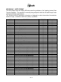
MIS DISPLAY - VIDTS FORMAT
The MIS Display Mode will display MIS data under the guidelines of the Vending Industry Data
Transfer Standard. This standard is currently being adopted in both the US and Europe under
various sanctioning organizations.
The following interval (resettable) information is displayed in order shown when the selection
switch one (up), or selection switch two (down), is pressed.
CODE
ID101
ID102
ID103
ID104
ID106
EA701
VA103
VA104
VA204
CA301
CA302
CA304
CA401
CA402
CA701
CA801
CA901
CA1001
CA1501
DA203
DA204
PA203-1
PA204-1
PA203-2
PA204-2
PA203-3
PA204-3
PA203-4
PA204-4
PA203-5
PA204-5
PA203-6
PA204-6
PA203-7
PA204-7
PA203-8
PA204-8
PA203-9
PA204-9
PA203-10
PA204-10
PA203-11
DESCRIPTION
Machine Serial Number
Machine Model Number
Code Revision
Machine Location
Machine Asset Number
Number of Power Outages
Value of all Paid Sales
Number of all Paid Vend
Number of Test Vends
Value of Cash In
Value of Cash to Cash Box
Value of Bills to Stacker
Value of Cash Dispensed
Value of Manual Cash Dispensed
Value of Cash Discount
Value of Cash Overpay
Value of Pay Vends Exact Change
Value of Cash Manually Added
Value Tube Contents
Value of Card Sales
Number of Card Sales
Number of Products Vended (Selection 1)
Value of Products Vended (Selection 1)
Number of Products Vended (Selection 2)
Value of Products Vended (Selection 2)
Number of Products Vended (Selection 3)
Value of Products Vended (Selection 3)
Number of Products Vended (Selection 4)
Value of Products Vended (Selection 4)
Number of Products Vended (Selection 5)
Value of Products Vended (Selection 5)
Number of Products Vended (Selection 6)
Value of Products Vended (Selection 6)
Number of Products Vended (Selection 7)
Value of Products Vended (Selection 7)
Number of Products Vended (Selection 8)
Value of Products Vended (Selection 8)
Number of Products Vended (Selection 9)
Value of Products Vended (Selection 9)
Number of Products Vended (Selection 10)
Value of Products Vended (Selection 10)
Number of Products Vended (Selection 11)
PR-12
MDB MECH
YES
YES
YES
YES
YES
YES
YES
YES
YES
YES
YES
YES
YES
YES
YES
YES
YES
YES
YES
YES
YES
YES
YES
YES
YES
YES
YES
YES
YES
YES
YES
YES
YES
YES
YES
YES
YES
YES
YES
YES
YES
YES
EXEC - MECH
YES
YES
YES
YES
YES
YES
NO
YES
YES
NO
NO
NO
NO
NO
YES
YES
YES
NO
NO
NO
NO
YES
YES
YES
YES
YES
YES
YES
YES
YES
YES
YES
YES
YES
YES
YES
YES
YES
YES
YES
YES
YES
CODE
PA204-11
PA203-12
PA204-12
PA102-1
PA102-2
PA102-3
PA102-4
PA102-5
PA102-6
PA102-7
PA102-8
PA102-9
PA102-10
PA102-11
PA102-12
DESCRIPTION
Value of Products Vended (Selection 11)
Number of Products Vended (Selection 12)
Value of Products Vended (Selection 12)
Price of Product (Selection 1)
Price of Product (Selection 2)
Price of Product (Selection 3)
Price of Product (Selection 4)
Price of Product (Selection 5)
Price of Product (Selection 6)
Price of Product (Selection 7)
Price of Product (Selection 8)
Price of Product (Selection 9)
Price of Product (Selection 10)
Price of Product (Selection 11)
Price of Product (Selection 12)
PR-13
MDB MECH
YES
YES
YES
YES
YES
YES
YES
YES
YES
YES
YES
YES
YES
YES
YES
EXEC - MECH
YES
YES
YES
YES
YES
YES
YES
YES
YES
YES
YES
YES
YES
YES
YES
MIS DISPLAY - VIDTS FORMAT (CONTINUED)
The following historical (non-resettable) information is displayed in order shown when the
selection switch three (up), or selection switch four (down), is pressed.
CODE
ID101
ID102
ID103
ID104
ID106
EA301
EA702
VA101
VA102
VA202
CA305
CA306
CA307
CA308
CA403
CA404
CA702
CA802
CA902
CA1002
DA201
DA202
PA201-1
PA202-1
PA201-2
PA202-2
PA201-3
PA202-3
PA201-4
PA202-4
PA201-5
PA202-5
PA201-6
PA202-6
PA201-7
PA202-7
PA201-8
PA202-8
PA201-9
PA202-9
PA201-10
PA202-10
PA201-11
PA202-11
PA201-12
PA202-12
DESCRIPTION
Machine Serial Number
Machine Model Number
Code Revision
Machine Location
Machine Asset Number
Number of Reads
Number of Power Outages
Value of all Paid Sales
Number of all Paid Vends
Number of Test Vends
Value of Cash In
Value of Cash to Cash Box
Value of Cash to Tubes
Value of Bills to Stacker
Value of Cash Dispensed
Value of Manual Cash Dispensed
Value of Cash Discount
Value of Cash Overpay
Value of Paid Vends Exact Change
Value of Cash Manually Added
Value of Card Sales
Number of Card Sales
Number of Products Vended (Selection 1)
Value of Products Vended (Selection 1)
Number of Products Vended (Selection 2)
Value of Products Vended (Selection 2)
Number of Products Vended (Selection 3)
Value of Products Vended (Selection 3)
Number of Products Vended (Selection 4)
Value of Products Vended (Selection 4)
Number of Products Vended (Selection 5)
Value of Products Vended (Selection 5)
Number of Products Vended (Selection 6)
Value of Products Vended (Selection 6)
Number of Products Vended (Selection 7)
Value of Products Vended (Selection 7)
Number of Products Vended (Selection 8)
Value of Products Vended (Selection 8)
Number of Products Vended (Selection 9)
Value of Products Vended (Selection 9)
Number of Products Vended (Selection 10)
Value of Products Vended (Selection 10)
Number of Products Vended (Selection 11)
Value of Products Vended (Selection 11)
Number of Products Vended (Selection 12)
Value of Products Vended (Selection 12)
PR-14
MDB-MECH
YES
YES
YES
YES
YES
YES
YES
YES
YES
YES
YES
YES
YES
YES
YES
YES
YES
YES
YES
YES
YES
YES
YES
YES
YES
YES
YES
YES
YES
YES
YES
YES
YES
YES
YES
YES
YES
YES
YES
YES
YES
YES
YES
YES
YES
YES
EXEC - MECH
YES
YES
YES
YES
YES
YES
YES
YES
YES
NO
NO
NO
NO
NO
YES
YES
YES
YES
YES
NO
YES
YES
YES
YES
YES
YES
YES
YES
YES
YES
YES
YES
YES
YES
YES
YES
YES
YES
YES
YES
YES
YES
YES
YES
YES
YES
CODE
PA102-1
PA102-2
PA102-3
PA102-4
PA102-5
PA102-6
PA102-7
PA102-8
PA102-9
PA102-10
PA102-11
PA102-12
DESCRIPTION
Price of Product (Selection 1)
Price of Product (Selection 2)
Price of Product (Selection 3)
Price of Product (Selection 4)
Price of Product (Selection 5)
Price of Product (Selection 6)
Price of Product (Selection 7)
Price of Product (Selection 8)
Price of Product (Selection 9)
Price of Product (Selection 10)
Price of Product (Selection 11)
Price of Product (Selection 12)
MDB-MECH
YES
YES
YES
YES
YES
YES
YES
YES
YES
YES
YES
YES
PR-15
EXEC - MECH
YES
YES
YES
YES
YES
YES
YES
YES
YES
YES
YES
YES
EVENT HISTORY DISPLAY
Switches 5 and 6 are used to view the Sold Out, Door History, and Exact Change history.
Switch 10 is used to display the time/date when the event occurred (the time/date is
displayed until another switch depression).
Door History is not reset; displays data from the last two times the door was opened.
The "Sold Out" and "Exact Change" events can be reset. If there have not been any
events since the last reset, none will be displayed. If there has been more than one event
since the last reset (e.g. the machine has gone into the Exact Change state twice), the
last occurrence will be logged (although the "Total Duration of Exact Change" is the total
of all time the machine has been in the Exact Change condition since the last reset).
Note that the door has to be closed for 30 seconds before an additional event is logged.
Sold outs displayed as:
Sold Out Sel x
X = the # of the sold out selection
Door history is displayed as:
Door Opened Last
When the door was last opened
Door Opened Prev
When the door was previously opened
The Exact Change information is displayed as:
Exact Change Det
Indicates that the machine was in the Exact Change State
When switch 10 is pressed, the time date is displayed as:
hh:mm dd/mm/yy dd
Where hh/mm is the time when the event occurred.
Where dd/mm/yy is the date when the event occurred.
Where dd is the duration in hours, for Exact Change.
PR-16
ERROR LOG DISPLAY
Switches 7 and 8 are used to view the error log. Switch 10 is used to display the time/date
when the event occurred (the time/date is displayed until another switch depression). The
error log can store 20 events (the last event to occur is the 1st displayed). If the log is empty
(due to reset), "No Errors" is displayed.
The possible error messages are:
Displays
Description
Coin Mech
When an MDB coin mech has reported an error.
Bill Acceptor (if used)
When an MDB bill acc. has reported an error.
Card Reader (if used)
When an MDB reader has reported an error.
Selection xx
When selection switch "xx" (01 - 12) is bad. (e.g. switch is
closed for >30 seconds)
Motor xx
When motor "xx" (A1 - E6) is assigned via STS, but is bad
Door Opened
When the door has been left open > 60 min
Touch
When there's a problem with Touch
DEX
When there's a problem with DEX
IrDA
When there's a problem with IrDA
Fraud Detect
When a fraud attempt has been detected (e.g. reported by a
card reader, etc.)
Chute Fraud
When a fraud at the chute has been detected
Bill Fraud
When a bill acceptor fraud has been detected (e.g. bill pull)
Battery
When the RAM is corrupted due to the battery
SW Mismatch
When the SW rev's mismatch (uP and Flash)
When switch 10 is pressed, the time/date is displayed as:
Hh:mm dd/mm/yy
Where hh:mm is the time when the event occurred.
Where dd/mm/yy is the date when the event occurred.
RESETTING THE MIS/HISTORY/ERROR LOGS
Switch 9 cycles through the different types of resets:
Displays
Reset MIS
Reset Event Log
Reset Error Log
Description
Resets Interval/Resettable fields
Resets the Event History Log (Sold Out and Exact Change
events)
Resets the Error log
Switch 10 performs the reset (the switch must be held for 2 seconds). The beeper will sound
once the reset has completed.
Note that errors are not auto-cleared from the log (e.g. if an error associated with switch 4 has
been posted, it will not automatically be removed when switch 4 is repaired).
PR-17
MODE # 7: ENTRY CODE MODE
By pressing the mode switch six times will enter the Entry Code Mode. Upon entry, the words
“Entry Code” will scroll on the display. Pressing selection switches 3, 1, 4, and 2 in sequence
enters the entry code. Once the correct entry code has been keyed in, the controller will not
need to key in the code again unless the door has been closed, or a five-minute service
timeout has occurred.
Note: In order to enter the Space to Sales Programming Mode, Display Programming Mode,
or the modes above (modes 8 - 14), the correct entry code must be keyed in. If the correct
entry code is not keyed in, the depression of the mode button will cause the Control System to
enter the Operate Mode.
MODE #8: SPACE TO SALES (STS) PROGRAMMING MODE
Pressing the mode switch seven times will enter the Space to Sales Programming Mode.
Upon entering the mode, the display will show "STS programming".
The VMC's Space to Sales is configured via 13 screens/lines. The 1st screen/line is used to
specify if a "Custom" or "Preset" STS is used. For each selection (1 - 12), there is an
additional screen/line used for setting its STS. Using selection switches 3 and 4 accesses the
screens/lines.
Once the desired screen/line is being displayed, selection switches 5 and 6 are used to move
the cursor to the desired position. Once the cursor is at the desired location, selection
switches 7 and 8 are used to change the setting.
Note that the selection switches 9 and 10 also move the cursor (multiple positions per
depression). Switches 11 and 12 will restore the STS to the setting that existed before the
mode was entered.
Selection
Switch
Number
1
3
5
7
9
11
Function
Selection
Switch
Number
Moves to Previous Screen
Moves the Cursor Left
Decrements the Value
Goes to the Previous Module
N/A
Restore
2
4
6
8
10
12
PR-18
Function
Moves to the Next Screen
Moves the Cursor Right
Increments the Value
Goes to the Next Module (A to B)
N/A
Restore
SELECTING A PREPROGRAMMED STS SETTING
With the display showing "STS Programming" (via the mode switch), depressing selection
switch 4 will move control to the 1st screen/line.
Preset STS Setting x (the cursor will be at the "x" location)
The "x" can be either a:
C indicates that the STS configuration is presently custom
1 - 9 indicates that the STS configuration is one of the presets (1 - 9)
With this screen, the operator can specify a custom STS or one of the preset STS
configurations. Via switches 7 and 8, changing the "x" to 1 - 9 will select one of the preset STS
settings (see the following table for the preset STS configurations). If the mode is exited after
the "x" is changed, then the STS configuration will correspond to the entered numerical
value.
STS #
Sel 1
Sel 2
Sel 3
ASSIGNED MOTORS PER SELECTION
Sel 4
Sel 5
Sel 6
Sel 7
Sel 8
Sel 9
1
B1, 2
C1, 2
A1-A3
D4
2
3
4
5
6
7
8
9
TBD
TBD
TBD
TBD
TBD
TBD
TBD
TBD
D1D3
E3, 4
B3
E1, 2
A4
Sel
10
C3
Sel
11
Sel
12
If the operator changes the settings to a number and then proceeds to the next screen/line, it
is possible to modify one of the preset settings. If a person does modify a preset setting, the
1st line will show a "C" (since it is a custom setting - even if it a variation of a preset setting).
CUSTOM SPACE TO SALES PROGRAMMING
With machine at the 1st screen/line (Preset STS Setting "x"), depressing selection switch 4 will
move the control to the 2nd screen/line. Examples of the line are shown below:
SEL01 A……B……
SEL A 34 B1…..
SEL A……B123456
Indicates that Selection 1 is not assigned to motors A1 - A6 or B1 - B6.
Indicates that Selection 1 is assigned to motors A3, A4, and B1.
Indicates that Selection 1 is assigned to motors B1 - B6.
For the screens/lines associated with the individual selections (as shown above), when a
number appears (as opposed to a "."), it indicates that the corresponding motor is assigned to
PR-19
the selection. So when the display shows "B..34.." it indicates that motors B3 and B4 are
assigned to the displayed selection (motors B1, B2, B5, and B6 are not assigned to the
selection).
SELECTING THE DIFFERENT SCREENS
Selection switches 3 and 4 can be used to access the other 12 screens (for viewing and
setting the STS for each of the 12 selections).
Preset STS Setting C
SEL01 A12….B……
SEL02 A……B1……
SEL03 A……B..34..
SEL12 A……B……
1st screen
2nd screen (sets the STS, Sel #1)
3rd screen (sets the STS, Sel #2)
4th screen (sets the STS, Sel #3)
Continues to…….
13th screen (STS, Sel #12)
VIEWING ALL OF THE MOTOR ASSIGNMENTS
Due to size of the display, only a portion of the information can be seen at a time (an example
of the complete information is shown below).
Selection switches 5 and 6 can be used to move the cursor one position at a time. Switches 9
and 10 move the cursor to the next module (e.g. A to B, or C to D). When the cursor reaches
the end of the screen/line (eg.. it's at the "6" for "A……B….56"), on the next switch depression
the screen shifts the modules (see the following examples).
If the screen shows (cursor at the last position):
After Switch 6 is hit (moves the cursor to the right), the screen will show"
If the screen shows (cursor at 2nd position):
After Switch 5 is hit (moves the cursor to the left), the screen will show:
If the screen shows (cursor at the "3" position):
After Switch 10 is hit (moves to the module on the left), the screen will show:
ASSIGNING A MOTOR TO A SELECTION
A motor can be assigned to a selection by changing the appropriate "." to a number (1 - 6). A
motor can be unassigned by changing the appropriate number (1 - 6) to a "." (see the following
example):
Assuming that the screen shows the following setting and the operator wants to assign
motor C1 to the selection and unassign D1.
The operator would first change the "." to a "1" (via switches 7 and/or 8).
The operator would then move the cursor to the D1 position (via switch 6).
PR-20
The operator would then change the "1" to a "." (via switches 7 and/or 8).
MODE #9: DISPLAY PROGRMMING MODE
By pressing the mode switch eight times, the controller will enter the Display Programming
Mode. Upon entering the mode, the display will show "Display Programming". Depressing a
selection switch will cause the following:
Selection
Switch
Number
1
3
5
7
9
11
Function
Selects English (default) or Alt Language
Decrements through Message List
Moves cursor left
Decrements value at cursor pos.
Insert space
Selects Display Configuration
Selection
Switch
Number
2
4
6
8
10
12
Function
Copies English to Alt.
Increments through Message List
Moves cursor right
Increments value at cursor pos.
Delete char at cursor
Selects options for Configuration
Switch 1 selects between the standard English messages and the alternate
(programmable/loadable) messages. Note that the alternate messages are loaded via
DEX.
Switch 2 copies the English messages into the alternate message area.
Switches 3 - 10 are used to change the alternate messages.
Switches 11 and 12 are used to control the information displayed to the user. Switch 11
cycles through 5 different parameters, while switch 12 cycles through the options
associated with the parameters. The parameters and their options are below:
Append the Block Time to the User Message
Blocker Time
No/12H/24H
(not displayed, 12 or 24 hour format)
Append Reason to the Out of Order Message
Display Fault
(not displayed, 12 or 24 hour format)
Append Time to the User Message
Display Time
No/12H/24H
Yes/No
Display Exact Change State (Append message, etc.)
Exact Chg
No/Some/Full
PR-21
Flash LED's if a Product is Discounted
Flash Discount Yes/No
After a machine reset, continuous depressions of switch 11 display:
Blocker Time
Display Time
Display Fault
Exact Chg
Flash Discount
Blocker Time
24H
No
Yes
Some
Yes
24H
MODE #10: MACHINE RESET MODE
The VMC allows four types of Machine Resets (beyond the MIS interval reset, the error log
reset, and the history event log reset).
Configuration Reset
Total Machine Reset
MIS Historical Reset
Time Percentage Reset
The Machine Reset Mode is entered when the door is opened and the mode switch is
depressed nine times. Upon entering the mode, the display will show "Machine Reset".
CONFIGURATION RESET
Once the display shows "Machine Reset”, hitting selection switch 4 will move control to the
next menu level, where the machine will display:
Config reset N
Hitting selection switch 7 or 8 will change the "N" to a "Y". Once the display shows:
Config reset Y
Hitting switches 9 or 10 will cause the machine's configuration to be reset to the default values.
TOTAL MACHINE RESET
Once the display shows "Machine Reset", hitting selection switch 4 (move to the next menu)
twice or switch 3 (move to the previous menu) once, will move control to the menu level, where
the machine will display:
Total Mach Reset N
PR-22
Hitting selection switch 7 or 8 will change the "n" to a "Y". Once the display shows:
Total Mach reset Y
Hitting switches 9 or 10 will cause a total machine reset. The following items will be reset:
Credit
Machine's configuration
MIS - Resettable data
MIS - Historical data
Error Logs
History Logs
Messages (Language will be set to English)
Old/New Door support (auto detection of machine type)
MIS HISTORICAL RESET
Once the display shows "Machine Reset", hitting selection switch 4 (move to the next menu)
three times or switch 3 (move to the previous menu) twice, will move control to the menu level,
where the machine will display:
MIS Historical Reset N
Hitting selection switch 7 or 8 will change the "N" to a "Y". Once the display shows:
MIS Historical Reset Y
Hitting switches 9 or 10 will cause the Historical MIS information to be reset.
Time Percent Reset
MODE #11: TOUCH UP/DOWN LOAD MODE
The Touch Up/Down Load Mode is entered when the door is opened and the mode switch is
depressed ten times. Upon entering the mode, the display will show "Touch Memory".
PR-23
With "Touch Memory" displayed, hitting selection switch 4 (one or more times) will move
control to the next menus:
Messages during the Touch Upload / Download are:
Displays
Description
TMU to Clrl config
Downloads the Config info to the Controller
TMU to Ctrl MSG
Downloads the Messages to the Controller
Ctrl to TMU Config Uploads the Config info to the TMU from the Controller
Ctrl to TMU Msg
Uploads the Messages to the TMU from the Controller
Ctrl to TMU MIS
Uploads the MIS information to the TMU
With any of the above messages on the display, hitting switches 9 or 10, will begin the
execution of the selected Up/Download. Once one of the data transfers has been initiated, the
operator must place a TMU (Touch Memory Unit) into the TMU socket. The unit must be held
in the socket until the VMC displays "Transmission Done".
Possible Messages during the Touch Mode are:
Displays
Description
Waiting for TMU
Indicates the VMC is waiting for the operator to attach the TMU.
Upload in Progress
Indicates data is transferring to the TMU
Download in Progress Indicates data is transferring to the VMC
Transmission Done
Indicates that the data transfer has been completed - the TMU can be
removed.
TMU Mismatch
Indicates that a specific download has been specified, but the TMU
contains a different type of data.
Transmission Failed
Indicates that the transmission failed.
Note, that if a touch chip is connected while the machine's door is opened and the machine is
in the operate mode (i.e. the mode switch has not been pressed), the VMC will automatically
do a MIS download to the chip.
MODE #12: SET TIME FUNCTIONS MODE
The Time Function programming mode is entered when the door is opened and the mode
switch is depressed eleven times. Upon entering the mode, the display will show "Time
Programming".
In this mode, the operator can:
Set the Machine's Time (2 screens/lines used for setup)
Set Blocker 1 (5 screens/lines used for setup)
Set Blocker 2 (5 screens/lines used for setup)
Set the Discount (6 screens/lines used for setup)
Note that at any time (while in the Time Programming mode), switches 11 & 12 can be used to
restore the previous configuration.
PR-24
ACCESSING THE DIFFERENT SCREENS & FIELDS
The VMC's time related settings are configured via 18 screens/lines. The screens/lines are
accessed by using Selection Switches 3 and 4. Once the desired screen/line is being
displayed, selection switches 5 and 6 are used to move the cursor to the desired position.
Once the cursor is at the desired location, selection switches 7 and 8 are used to change the
setting.
LED INDICATION
The LED associated with each selection switch indicates if a selection is effected by a specific
feature. If the first 2 letters of the message are"B1", then the LED's indicate which selections
have been tied to Blocker 1 (red LED on ON). If the first 2 letters of the message are "B2",
then the LED's indicate which are tied to Blocker 2; and if the letters are "D1", then the LED's
indicate which selections will be effected by the programmed discount.
SETTING A SELECTION, TO BE AFFECTED BY A FEATURE
If the message is "xx Set Selections Y", then for each selection, a selection can be tied to the
feature (B1, B2, D1) by pressing the appropriate selection switch (the selection can be
deselected by pressing the switch a second time). The state of the LED (associated with the
selection switch) will change to reflect if the selection is tied to the feature (LED is red) or if it
has been deselected (LED is off). The mode for specifying which selections are affected by
the feature is exited by hitting the mode switch or by not hitting any switch for 10 seconds
(auto reverts back to "xx Set Selection N").
SET TIME
When the display shows "Time Programming", hitting selection switch 4, moves control to the
screen used for setting the machine's time:
Times hh:mm dd/mm/yy
Via switches 5 and 6, the cursor can be moved between the hour, minute, day, month, and
year fields. While in a field, switches 7 and 8 can be used to change value. Note that a 24hour clock is used here.
With the display showing the time, hitting switch 4 again moves control to the screen used for
setting the type of Daylight Savings Time:
DST N., America
Via switches 7 and 8, the Value/type can be set to:
None
N. America
Europe
Australia
PR-25
SET BLOCKER 1 & 2
With the display showing the Daylight Savings type, hitting switch 4 again, moves control to the
screens used for setting the parameters associated with Blocker 1 (hitting switch 4 six times,
will move to the screens associated with Blocker 2; which is set up exactly like
Blocker 1).
Displays
B1 Blocker active Y
B1 ON hh:mm mtwtfss
B1 OFF hh:mm mtwtfss
B1 Ext Switch Y
B1 Set Selections Y
Definition
"Y" indicates that the feature is enabled. "N" is disabled
Indicates the time when the blocker is active (hh:mm) and for what days
(upper case indicates that the blocker will be turned on for that day).
Indicates the time when the blocker is deactivate (hh:mm) and for what
days (upper case indicates that the blocker will be turned off for that day).
"Y" indicates that the external switch must be active (closed) for the
feature to be active. "N" indicates that the external switch is not used.
"Y" indicates that the selection switches are used to specify which
selections the Blocker 1 feature effects.
For the ON and OFF screens, the cursor can be moved between the different fields (hour,
minute, Monday enable, Tuesday enable, Wed. enable, Thursday enable, Friday enable,
Saturday enable, and Sunday enable). Once in the field, the values can be changed via
switches 7 and 8 ("Y" to "N", hh = 00 - 23, mm = 00 - 59, m = "m" or "M", t = "t" or "T", …).
The screens/lines for Blocker 2 follow the screens associated with Blocker 1 (they are set up
exactly the same).
Displays
B2 Blocker active Y
B2 ON hh:mm mtwtfss
B2 OFF hh:mm mtwtfss
B2 Ext Switch Y
B2 Set Selections Y
Definition
"Y" indicates that the feature is enabled. "N" is disabled
Indicates the time when the blocker is active (hh:mm) and for what days
(upper case indicates that the blocker will be turned on for that day).
Indicates the time when the blocker is deactivate (hh:mm) and for what
days (upper case indicates that the blocker will be turned off for that day).
"Y" indicates that the external switch must be active (closed) for the
feature to be active. "N" indicates that the external switch is not used.
"Y" indicates that the selection switches are used to specify which
selections the Blocker 1 feature effects.
SET DISCOUNT
The screens/lines for setting up the Discount follow the screens associated with blocker 2 (they
are set up almost in the same manner).
Displays
D1 Blocker Active Y
Definition
"Y" indicates that the feature is enabled. "N" is disabled.
D1 Amount xxx.xx
D1 ON hh:mm mtwtfss
Indicates the amount of the discount.
Indicates the time when the discount is active (hh:mm) and for what days (upper case
indicates that the blocker will be turned on for that day).
Indicates the time when the discount is deactivate (hh:mm) and for what days (upper
case indicates that the blocker will be turned off for that day).
"Y" indicates that the external switch must be active (closed) for the feature to be
active. "N" indicates that the external switch is not used.
"Y" indicates that the selection switches are used to specify which selections the
discount feature effects.
D1 OFF hh:mm mtwtfss
D1 Ext Switch Y
D1 Set Selection Y
PR-26
For the ON and OFF screens, the cursor can be moved between the different fields (hour,
minute, Monday enable, Tuesday enable, Wed. enable, Thursday enable, Friday enable,
enable, Saturday enable, and Sunday enable). Once in the field, the values can be changed
via switches 7 and 8 ("Y" to "N", xxx.xx = 000.00 - 650.00, hh = 00 - 23, mm = 00 - 59, "m" or
"M", t = "t" or "T", …).
MODE # 13: TOKEN ENABLING MODE
The Token Enabling Mode is entered when the door is opened and the mode switch is
depressed twelve times. Upon entering the mode, the display will show "Token Enable".
While in the mode (display shows "Token Enable"), hitting a selection switch will toggle the
setup for the associated selection. If the LED is red, then the selection can be purchased with
a token. If the LED is off, then the selection cannot be purchased with a token.
MODE # 14: SET MIS ACCESS MODE
The "Set MIS Access" programming mode is entered when the door is opened and the mode
switch is depressed thirteen times. Upon entering the mode, the display will show "Set MIS
Access".
In this mode, the operator can:
Restrict access to the Optics communications
Restrict access to the Door Closed DEX comm.
Restrict access to the Door Closed MIS display
Change the Optics password
Change the password for the Door Closed MIS retrieval
Note that at any time (while in this programming mode), switches 11 & 12 can be used to
restore the previous configuration.
LIMITING ACCESS FOR THE OPTICS COMMUNICATIONS
With the display showing "Set MIS Access", hitting switch 1 will move control to the mode
where the access to the IrDA optics communication is set. Additional depressions will change
the setting to one of the other options.
PR-27
Displays
IrDA Audit Only
IrDA Audit/Config
IrDA Disabled
Definition
Indicates that MIS audit info can be retrieved from the VMC, but the VMC can not
be configured via optics.
Indicates that the MIS audit info can be retrieved from the VMC, plus the VMC
can be configured via optics.
Indicates that the optics communication is disabled.
REQUIRING A PASSWORD FOR THE OPTICS COMM.
With the display showing "Set MIS Access", hitting switch 2 will move control to the mode
where the requirement for a password (to initiate the IrDA optics communication), is set. The
first time switch 2 is pressed, the display will show the present setting; additional depressions
will change the setting to one of the other options.
Displays
IrDA Password Y
Definition
Indicates that a password must be entered before the optics communication can begin
IrDA Password N
Indicates that a password is not required to begin the optics communications.
LIMITING ACCESS FOR THE DEX COMM (W/DOOR CLOSED)
With the display showing "Set MIS Access", hitting switch 3 will move control to the mode
where the access to the DEX communication (with the door closed), is set. The first time
switch 3 is pressed, the display will show the present setting. Additional depressions will
change the setting to one of the other options.
Displays
CD DEX Audit Only
CD DEX Audit/Config
CD DEX Disabled
Definition
Indicates that MIS audit info can be retrieved from the
VMC, but the VMC can not be configured via DEX.
Indicates that the MIS audit info can be retrieved from the
VMC, plus the VMC can be configured via DEX.
Indicates that the DEX comm (when the door is closed) is
disabled.
LIMITING ACCESS FOR MIS DISPLAY (W/DOOR CLOSED)
With the display showing "Set MIS Access", hitting switch 4 will move control to the mode
where the access to the MIS information (via the display - with the door closed), is set. The
first time switch 4 is pressed, the display will show the present setting; additional depressions
will change the setting to one of the other options.
Displays
Closed Door MIS Y
Closed Door MIS N
Definition
Indicates that MIS audit information can be retrieved from
the VMC.
Indicates that the MIS audit info can not be displayed
when the door is closed.
ENTERING THE PASSWORD FOR THE OPTICS COMM (RECOMMENDED)
With the display showing "Set MIS Access", hitting switch 5 will move control to the mode
where the optics' password is displayed and changed. The first time switch 5 is pressed, the
display will show the present password (e.g. the default is "1212"). An additional depression
PR-28
will put the machine into the mode for changing the password. While in this mode, switches 1 4 are used to enter the new password (e.g. switch 1 is used to enter a "1", etc.), while all other
switches exit the mode.
Displays
IrDA Password 1212
IrDA Password
Definition
Indicates the present password
Indicates that the next 4 switch depressions will be used as the
new password. As the keys are entered, they are displayed.
PR-29
NOTES
PR-30
MAINTENANCE SECTION
M-1
MAINTENANCE
The following section is a basic guide for general maintenance and servicing of the vendor.
This section is divided into three parts:
(I)
(II)
(III)
I.
PREVENTATIVE MAINTENANCE SUGGESTIONS:
Whenever a vendor is visited on its site, the following service should be performed.
Preventative maintenance will help prevent future problems with the vendor.
A.
B.
C.
D.
E.
F.
G.
H.
I.
J.
K.
L.
M.
II.
Preventative Maintenance Suggestions
Lubrication Guide
Care and Cleaning
Observe the vendor and its surrounding area for any unusual indications of
problems (rear on cabinet, obstructions of the air flow, dark spots on the sign face,
etc.).
Open the door and visually check the inside of the vendor (water accumulation,
rust marks, moisture around the edges of the inner door, etc.).
Check the fluorescent lamps, replace as necessary. Replace lamps within 24 to
48 hours of burnout. This will prevent damage to the ballast.
Check the product temperature for proper cooling.
Check evaporator drain for obstruction; water in the evaporator area must drain to
the condensate pan.
Empty condensate pan.
Clean the condenser, free vanes of dirt, lint, etc.
Check that evaporator fan runs normally.
Check that the compressor and condenser fan run normally.
Investigate any unusual sounds (fan blades hitting something, refrigeration lines
rattling, etc.).
Clean coin acceptor.
Deposit all coinage accepted by the vendor to check for proper operation of the
coinage mechanism.
Test the vendor and make a report on the problems.
LUBRICATION GUIDE:
Lubricate indicated areas as directed on the chart below.
INTERVALS
PARTS
LUBRICANT
Every six months
Top hinge of door, hinge pin at the Grade two, high - low
base of cabinet, T-handle shaft &
temperature grease
latch.
M-2
III.
A.
CARE AND CLEANING
AVOID USING WATER OR ANY OTHER
LIQUIDS NEAR ELECTRONIC
COMPONENTS.
DO NOT USE WATER JET FOR
CLEANING.
GENERAL PROCEDURE (painted metal areas)
Wash vendor with soap and water. The exterior may be waxed with any good
automobile wax.
B.
FRESH PAINT SPLASHES, GREASE, GLAZING COMPOUND REMOVAL
Before drying, these elements may be removed by rubbing lightly with grade “A” Naptha
(or equivalent grade solvent). After removal, use general cleaning procedure (listed
above as A).
C.
LABELS AND STICKER REMOVAL
Use any specialized label removal liquid. When the label material does not allow
penetration of solvent (such as vinyl), the application of heat (ie - hot air gun), will soften
the adhesive and promote removal. CAUTION: Excessive heat can cause surface
damage. After the label is removed, use the general cleaning procedure (listed above
as A).
D.
SCRATCH REMOVAL
Remove or minimize hairline scratches and minor abrasions by using any good quality
automobile polish. Test product before using.
E.
LEXAN SIGNS
To clean Lexan sign faces, the following procedure is recommended.
1.
Wash sign with mild soap, or detergent, and lukewarm water.
2.
Using soft cloth or sponge, gently wash the sign. DO NOT SCRUB!
3.
Rinse well with clean, lukewarm water.
4.
Dry thoroughly with a chamois or cellulose sponge (to prevent water
spotting). DO NOT USE SQUEEGEE!
NOTE: Most organic solvents, petroleum spirits, or alcohol, are NOT compatible
cleaning materials for Lexan signs.
Usage of those materials could
permanently damage the sign.
F.
REFRIGERATION AREA
The condenser and evaporator must be kept clean for efficient operation. Be sure all
vanes and tubing are clean and clear of obstruction; this allows free passage of air.
Clean with a brush, a vacuum cleaner, or compressed air. Keep cabinet drain open;
clean as necessary.
M-3
REFRIGERATION OPERATION
The refrigeration operation section is divided into three areas: Basic Refrigeration Principle,
detailed Vending Machine Refrigeration Cycle, and Parts Description.
BASIC REFRIGERATION PRINCIPLE
What a refrigeration system really accomplishes is the transfer of heat. A refrigeration system
removes the excess heat from a refrigerated area and then transfers it to a condenser, where
it is dissipated. As heat is removed, the refrigerated area cools.
In vending machines, large quantities of the heat must be transferred rapidly, economically,
and efficiently. This process must be able to withstand continuous repetition, without loss of
refrigerant, over an extended period. The most common system used in the vending industry
is the vapor compression (or simple compression), cycle system. It consists of four basic
elements: an evaporator, a compressor, a condenser, and a pressure-reducing device (all part
of a sealed system).
The compression system operates at two pressure levels: The low evaporating pressure, and
the high condensing pressure. The refrigerant acts as the transport medium, in which heat is
moved from the evaporator to the condenser; at the condenser, the heat is dissipated into the
surrounding air.
The liquid refrigerant changes from a liquid to a vapor, and back to a liquid again. This change
of state allows the refrigerant to absorb, and rapidly discharge, large quantities of heat
efficiently.
BASIC VAPOR COMPRESSION SYSTEM CYCLE DESCRIBED:
In the evaporator, the liquid refrigerant vaporizes. This change occurs at a temperature low
enough to absorb heat from the refrigerated space. The pressure maintained in the
evaporator (the higher the pressure, and the higher the vaporization point) controls the
temperature of vaporization.
The compressor pumps the vapor from the evaporator, through the suction line, and to the
condenser. The compressor takes the low-pressure vapor and compresses it, increasing both
the pressure and the temperature. The compressor pumps the vapor at a rate rapid enough to
maintain the ideal pressure. The hot, high-pressure vapor is forced out of the compressor, into
the discharge line, and then into the condenser.
Air is blown through the condenser, allowing heat to transfer from the condenser, and into the
passing air. As the heat is removed, the stored refrigerant is condensed into a liquid. The
liquid refrigerant is stored in the lower tube of the condenser. It is there, available to flow
through the restricted tube back into the evaporator, where the refrigeration cycle is repeated.
M-4
DETAILED REFRIGERATION CYCLE
The following is a detailed refrigeration cycle as it applies to the refrigeration system installed
in Vendo equipment. (Refer to the flow chart in Figure 17.)
The evaporator fan pulls air from the front of the refrigerated space of the cabinet. It pulls the
air through the evaporator, and blows it up the back of the modules. (The evaporator fan runs
continuously.) As the air passes through the evaporator, heat is drawn from the air and
transferred to the liquid refrigerant. As the cooled air circulates through the modules, heat is
drawn from the product and transferred to the circulating air. The heated air is again drawn
through the evaporator where the heat is removed.
In the evaporator, the liquid refrigerant draws heat from the circulating air. As refrigerant
receives heat, it vaporizes.
The compressor pumps the vapor from the evaporator and compresses it (increasing both
pressure and temperature). The compressor forces the compressed vapor out, through the
discharge line, and into the condenser.
The condenser fan pulls air through the condenser. As the hot refrigerant vapor passes
through the condenser tubes, heat is drawn from the vapor. This heat is dissipated into the
passing air. The air then exits out the back of the vendor. As the refrigerant vapor in the
condenser lines is cooled, it returns to a liquid state.
From the condenser the liquid flows to the drier. The drier removes any water and solid
particles from the liquid refrigerant.
The cooled liquid refrigerant continues from the drier, through the capillary tube, to the
evaporator. The capillary tube steadies the flow rate of the refrigerant. Its small inside
diameter allows the pressure in the evaporator to remain low while the pressure in the
condenser is high.
The cool refrigerant in the evaporator draws heat from the circulating air in the cabinet. As the
temperature in the cabinet drops, the temperature sensor reports the air temperature.
M-5
COMPRESSOR
SUCTION
DISCHARGE
LOW PRESSURE
SIDE
HIGH PRESSURE
SIDE
ACCUMULATOR
VAPOR
VAPOR
EVAPORATOR
110
CONDENSER
50
EVAPORATOR
FAN
CONDENSER
FAN
LIQUID
LIQUID
CAPILLARY RESTRICTION TUBE
DRIER
FIGURE 17
M-6
REFRIGERATION PARTS DESCRIPTION
The compressor, condenser, drier, capillary tube, evaporator, and accumulator are
part of a sealed system (refer to Figure 18). These items are not available
separately. For the part number of the sealed refrigeration system, refer to the
common parts section of the manual.
COMPRESSOR
The compressor takes in low-pressure vapor and compresses it, increasing both the
pressure and the temperature. The hot, high-pressure gas is forced out to the
condenser. The compressor, and the motor that drives the compressor, are sealed
inside a housing. The compressor, as a unit, is mounted on the refrigeration base.
The base is mounted in the bottom of the vendor, outside the sealed refrigeration
space.
CONDENSER
The condenser takes heat out of the high-pressure vapor that it receives from the
compressor. As the vapor passes through the condenser, it cools and returns to a
liquid state. The condenser is mounted to the refrigeration base near the front of the
vendor. It is easily accessible for cleaning.
DRIER (Not Shown)
The drier is a molecular sieve strainer/drier. It removes water and solid particles
from refrigerant liquid. One side of the drier is connected to the outlet line of the
condenser; the other side is connected to the capillary tube going to the evaporator.
CAPILLARY TUBE
The capillary tube controls, at a steady rate, the flow of refrigerant liquid to the
evaporator. It has a very small inside diameter to keep pressure in the evaporator
low while the pressure in the condenser is high. It is the connecting link between the
condenser and evaporator.
EVAPORATOR
The evaporator is a heat transference device. It removes the heat from the air in a
refrigerated space and transfers it to the refrigerant liquid. This liquid evaporates
into a vapor and is sucked out by the compressor. The evaporator is mounted inside
the refrigerated space of the cabinet, directly below the delivery chute.
ACCUMULATOR
The accumulator traps any refrigerant liquid that did not boil off into a vapor before
reaching the compressor. The accumulator allows the refrigerant liquid to boil off as
a vapor (preventing damage to the compressor). It also prevents suction line
sweating. The accumulator is mounted in the suction line on the outline side of the
evaporator.
M-7
EVAPORATOR
EVAPORATOR FAN
ACCUMULATOR
CONDENSER
COMPRESSOR
CAPILLARY TUBE
CONDENSER FAN
STARTING RELAY
FIGURE 18
(The parts listed below are not part of the sealed refrigeration system and are
available separately. For part numbers, see the refrigeration assembly in the
common parts section of the manual.)
CONDENSER FAN ASSEMBLY
The condenser fan pulls cool air from outside the vendor, through the condenser,
over the compressor, and blows it out the back of the vendor. This cool air removes
excess heat from refrigerant in the condenser. The condenser fan runs when the
compressor is engaged. The fan assembly is mounted on the refrigeration base
between the condenser and compressor.
EVAPORATOR FAN ASSEMBLY
The evaporator fan pulls air from the front of the refrigerated space, through the
evaporator, up the rear of the refrigerated space into the modules. The fan blows air
through the evaporator (which removes the heat from the air). It circulates the cool
air over the product, removing excess heat from the product. The evaporator fan
assembly is mounted to a fan bracket, mounted to the extensions of the evaporator.
These parts are located in the refrigerated area of the cabinet.
M-8
START RELAY – ASSEMBLY P/N: 513501587 (115 volts), 1016644-2 (230 volts)
The starting relay is mounted in the terminal box on the side of the compressor
housing. When the compressor first starts up, the starting relay closes and
completes a starting circuit. When the compressor motor reaches operating speed,
the starting relay opens and breaks the starting circuit.
THERMAL OVERLOAD SWITCH
The thermal overload switch is mounted in the terminal box on the side of the
compressor housing. If the compressor motor gets hot, or draws too much current,
the thermal overload opens and breaks the starting and running circuit of the motor.
As the motor cools, the thermal overload closes, allowing the compressor to run.
M-9
M-10
M-11
Refrigeration Wiring Diagram
* For Lighting Wiring Diagram, please see ballast.
M-12
NOTES
M-13
PARTS SECTION
PS-1
READING A PARTS LIST
I.
ITEM NUMBER is found in two locations:
A. It is on the drawing plate, and identifies the part and its location.
B. The same number is in the parts list and ties the two together.
II.
PART NUMBER is the part number that is assigned to a specific part by Vendo for easier
identification.
III.
QUANTITY REQUIRED relates to the amount required of a part, or will be indicated by “A/R”
as required to attach it on another part.
IV.
PART NAME AND DESCRIPTION is the general description for the part, for easier identification
when ordering a like part.
The example below will show how the parts are listed in the parts list:
1.
THE LEFT -HAND BAR MODULE: This is the main assembly named, and any replaceable
parts will be indented below the assembly.
2.
VEND MOTOR: This is a sub-assembly, and will be indented.
3.
VEND HELIX: This is a component part, and will be indented. These indented parts can be
ordered separately, so you do not need to order the entire assembly.
4.
Whenever an assembly is ordered, all the parts that are indented will be in the assembly. Any
hardware will be listed next to their corresponding parts.
5.
Any parts that may be ordered separately will not have any indented parts listed below them.
MARS VENDO CONFECTIONERY VENDOR
NUMBER
1
2
PART NUMBER
DESCRIPTION
# REQ. HARDWARE
1010387
Hanger Module
A/R
V801490
1121238
Slide Assembly (**)
2
V800634
***** LEFT-HAND BAR MODULE *****
3
1011103-4
Left-hand Bar Module Assy (*)
A/R
-------4
1010867
Door Assembly
4
-------5
1012738
Bushing - Door Pivot
4
-------6
1075716
Vend Motor
4
V802180
7
1010379
Module Top - Left
1
V800634
8
1049651
Vend Helix
4
-------9
1010301
Helix Bearing
4
-------If an asterisk is listed below the parts list, it is an indication that special information is noted. There may be more
than one (*) (**) (***) asterisk denoting special notes.
PS-2
Hardware List
PS-3
PS-4
AP V802185
#8 X 3/8” PH CROSS RECESSED “PLASTITE”……
AQ V802186
#4 X 1/4 PH “PLASTITE”…………
AR V802183
M3 X 8 FH MACHINE SCREW………………….….
PS-5
2
1
13
3
4
12
5
10
11
9
6
1
14
2
8
7
PS-6
OUTER DOOR COMPONENTS MARS VENDO CONFECTIONERY
ITEM
NO.
1
2
3
4
5
6
7
8
9
10
11
12
13
~
~
14
~
~
PART NO.
QTY
V801491
388094
1119694
~
1120984
1119694-1
1120911
1121436
1121980
1120941
1120953
1121948
1121948-1
2008813-00
2008813-01
2008813-02
2010162-01
2010162-02
2010162-03
3
2
1
1
2
1
1
1
1
1
1
1
1
1
1
1
1
1
DESCRIPTION
FLAT WASHER
BUSHING - HINGE
SIGN CAP – TOP MOLDING
SIGN FACE **
TRIM, SIGN FACE
SIGN CAP - BOTTOM MOLDING
HOPPER BEZEL
VEND FLAP MOULDING
PROMOTIONS PANEL - BLACK
SELECTION BUTTON ASSY (SEE PGS PS-8 & 9)
PROMOTIONS LABEL
ANTI-VANDAL PANEL, INTERNATIONAL OR
ANTI-VANDAL PANEL, U.S.
RAIN GUARD, BLACK
RAIN GUARD, BROWN
RAIN GUARD, YELLOW
DOOR GUARD, BROWN
DOOR GUARD, YELLOW
DOOR GUARD, BLACK
*NOTE: WHEN ORDERING OUTER DOOR ASSEMBLY, PLEASE PROVIDE 11 CODE AND
MANUFACTURER’S DATE CODE.
**NOTE: WHEN ORDERING SIGN FACE, PLEASE PROVIDE STYLE.
PS-7
HARDWARE
--V801421
-V801421
V801421
V802185
--
----V801434
V801434
V801434
SELECTION PANEL
PS-8
SELECTION PANEL COMPONENTS MARS VENDO CONFECTIONERY
ITEM
NO.
1
2
3
4
5
6
7
8
9
PART NO.
QTY.
1120941
1120916
1120912
1120923
1121795
1120926
1121035
1122906
~
1
12
7
12
12
12
12
1
12
DESCRIPTION
BUTTON PANEL ASSEMBLY
SELECTION BUTTON
BUTTON BRACKET CHASSIS
BUTTON CHASSIS
LED, BI-COLOR
LED / FLAVOR STRIP HOLDER
SWITCH SELECTION
BUTTON PANEL
FLAVOR STRIP*
FOR HARNESS PART NUMBERS, SEE PAGE PS-38
* NOTE: WHEN ORDERING FLAVOR STRIPS, PLEASE PROVIDE STYLE
PS-9
HARDWARE
V800952
------V800952
--
OUTER DOOR
8
22
9
23
22
10
12
13
11
14
16
7
18
15
SEE
PAGE PS-14
FOR DETAIL
17
21
5
6
16
2
15
20
19
4
SEE
PAGE PS-12
FOR DETAIL
1
3
PS-10
OUTER DOOR COMPONENTS MARS VENDO CONFECTIONERY
ITEM
NO.
1
2
3
4
5
6
7
8
9
10
11
12
PART NO.
QTY.
DESCRIPTION
1
1
1
1
1
1
1
2
4
2
1
1
13
14
1122687
1120942
1120973
1120972
1120963
1121003
1120946
388531
1122305
1121030
388532
1120450
1121732
1121954
1002635
1
1
COIN BOX WELD ASSEMBLY
COINAGE DOOR BRACKET ASSEMBLY
COIN BOX DOOR ASSEMBLY
HOPPER ASSEMBLY
LOWER RETURN CHUTE
LARGE RETURN CHUTE, UPPER
COIN ENTRY ASSEMBLY
LAMP HOLDER - FIXED
BRACKET LAMP HOLDER
FLUORESCENT LAMP
LAMPHOLDER – PLUNGER
BALLAST – 230 VOLTS
OR
BALLAST – 115 VOLTS
CONTROLLER ASSY (SEE PAGE PS-16 & 17)
T-HANDLE LOCK ASSEMBLY
15
16
17
18
19
20
21
22
23
1120994
1121002
1121986
1121987
1120938
1120974
1121448
1121444
2000848
3
3
1
1
1
1
1
1
1
HINGE
HINGE PIN
COINAGE DOOR REFLECTOR
RIGHT HAND DOOR FRAME REFLECTOR
BAFFLE, COIN BOX
BRACKET, COIN BOX SUPPORT
BAFFLE, COIN MECH
BAFFLE, DBV (U.S. ONLY)
RAIN GUTTER, EN APPROVED – INT’L ONLY
FOR HARNESS PART NUMBERS, SEE PAGE PS-38
PS-11
HARDWARE
---V800952
V801421
~
V801421
----V800955
-V800959/
V801023
----V801421
V800952
V801421
V800956
V802123
PS-12
REFUND MOTOR ASSEMBLY MARS VENDO CONFECTIONERY
ITEM
NO.
1
2
3
4
5
6
7
PART NO.
QTY.
1120982
1120983
1121012
1121031
V802190
V802183
1121034
1
1
1
1
1
3
1
DESCRIPTION
COIN ENTRY CHUTE
COIN ENTRY CHUTE COVER
REFUND MOTOR
CAM, REFUND
SET SCREW
FH MACHINE SCREW
REFUND SWITCH
FOR HARNESS PART NUMBERS, SEE PAGE PS-38
PS-13
COIN ENTRY ASSEMBLY
8
8
8
7
8
9
6
2
1
3
4
PS-14
5
COIN ENTRY ASSEMBLY MARS VENDO CONFECTIONERY
ITEM
NO.
1
2
3
4
5
6
7
8
9
PART NO.
QTY.
1120920
368299
1122156
1120927
1121684
1121453
1121435
V802186
1122346
1
1
1
1
1
2
4
7
1
DESCRIPTION
COIN ENTRY MOLDING
SWITCH
REFUND BUTTON SPRING
COIN RETURN BUTTON
DISPLAY
PCBA, IRDA, MARS MILLENNIUM
FLUORESCENT LENS FILTER
SCREW, #4 X 1/4, “PLASTITE”
50 CENT BLOCKER (U.S. ONLY)
PS-15
HARDWARE
----------
3
5
1
F
7
F
4
8
7
2
F
7
9
PS-16
CONTROLLER ASSEMBLY MARS VENDO CONFECTIONERY
ITEM
NO.
1
2
3
4
5
6
7
8
8
9
PART NO.
QTY.
1120996
1122024
1121439
1121740
1016288
384692-2
1008722
1122155
1050058
1122275
1
1
1
6
1
1
1
1
1
DESCRIPTION
CONTROL BOARD HOUSING
MARS MILLENNIUM CONTROL BOARD
CONTROL BOARD COVER
STANDOFF
BUSHING
PUSH MOUNT CLAMP (NOT PICTURED)
FUSE HOLDER
FUSE, 4 AMP SLOW BLOW – INT’L
FUSE, 4 AMP – U.S.
I-BUTTON PROBE ASSEMBLY
* FOR HARNESS PART NUMBERS, SEE PAGE PS-38
PS-17
HARDWARE
V801421
---------
INNER DOOR
PS-18
INNER DOOR ASSEMBLY MARS VENDO CONFECTIONERY
ITEM
NO.
1
2
3
4
5
6
7
8
9
10
11
12
PART NO.
QTY.
DESCRIPTION
HARDWARE
13430218
13430216
1121286
1010239
389985-1
388090
388305
V329258
1120697
1018159
1011367
389622-3
1010182
1
INNER DOOR PANEL ASSEMBLY – INTERNATIONAL OR
INNER DOOR PANEL ASSEMBLY – U.S.
--
2
1
1
2
1
1
1
1
2
1
1
HINGE LEAF - INNER DOOR
VEND DOOR - INNER DOOR
HINGE ROD - INNER DOOR
GROMMET
KNOB
CARRIAGE BOLT
PLUNGER BRACKET
PLUNGER
GROUND STRAP
GASKET KIT
EYELET INNER DOOR
PS-19
V801489
-V800570
---V801489
V801471
---
CABINET ASSEMBLY
1
30
42
SEE PAGE PS-22
FOR DETAIL
29
2
31
3
22
28
4
27
26
25
32
24
33
23
5
43
6
40
9
7
SEE PAGE PS-24
FOR DETAIL
20
8
10
11
12
36
19
39
34
18
41
35
13
37
38
15
14
16
21
17
3.02
PS-20
CABINET ASSEMBLY MARS VENDO CONFECTIONERY
ITEM NO.
1
2
3
4
5
6
7
8
9
10
10
11
12
13
14
15
16
17
18
19
20
21
22
23
24
25
26
27
28
29
30
31
32
33
34
35
36
37
38
39
40
41
42
43
PART NO.
2000805-03
389463
324099-4
1122194
1016237
1027611
1068678
387837
388143
1122688
1123015
387925
389071
1088449
1112023
1120387
1017861
1066961
1089236
388387
1123080
1123040
1087813
389026
1079112
389022
389023
1111988
389690
1076317
1076007
1017888-1
1027085
1027603
~
1059902
1112999
1073627
1121812
1123041
1122160
2001376
2010165-00
1123064
QTY.
1
1
AR
AR
4
1
1
1
2
1
1
1
1
1
1
1
1
1
1
2
1
1
1
2
1
1
3
1
1
4
1
1
1
1
1
4
1
1
1
1
1
1
1
1
DESCRIPTION
TOP HINGE WELD ASSEMBLY
RAIN GASKET - CABINET
HARNESS CLAMP
HARNESS CLIP ADHESIVE
BEARING - MODULE GUIDE
FRONT STRAP
DRAIN TUBE - CABINET
GASKET - DRAIN TUBE
CLOSURE CAP
AIR DAM – LEFT – DOMESTIC
AIR DAM ASSEMBLY, INT’L
NUT -DRAIN TUBE
LOWER HINGE PIN
DRAIN HOSE
CONDENSATE PAN
RAMP - DOOR ROLLER
TRANSFORMER 110/24V (U.S.)
TRANSFORMER COVER
AIR DAM - RIGHT
BRACKET - REFRIGERATION SYSTEM
SAFETY SCREEN
BAFFLE, TRANSFORMER
QUICK-LOCK ASSEMBLY
FLAT WASHER
BRACKET - QUICK LOCK
RETAINER - NUT SEGMENT
NUT SEGMENT (3 REQUIRED)
CAP
SPRING
MODULE STOP
MODULE STOP GUIDE
PRODUCT CHUTE ASSEMBLY
CHUTE SUPPORT (SEE PGS PS-22 & 23)
DEFLECTOR BRACKET
OPTIC ASSEMBLY (SEE PGS PS-24 & 25)
LEVELING LEG
DEFLECTOR CHUTE
BRACKET - AIR DAM
COUNTER WEIGHT - INT’L
BAFFLE, CORDSET – INT’L
PINCH GUARD, BLACK
OVERLAP GUARD – SIDE BLACK
OVERLAP GUARD – TOP BLACK
RAIN CURTAIN, COMPRESSOR – INT’L
FOR HARNESS PART NUMBERS, SEE PAGE PS-38
PS-21
HARDWARE
V801434
-V801489
--V802133
--V801489
V801489
V801489
----V802173
V801489
V801489
V801490
V801489
V802147
V801490
V802139
-------V801489
V801489
-V801489
----V802069
V802069
V802069
--
ELECTRONIC COMPONENTS
5
2
4
3
1
PS-22
ELECTRONIC COMPONENTS MARS VENDO CONFECTIONERY
ITEM
NO.
1
2
3
4
5
PART NO.
QTY.
1121825
323007
1122298
V801449
1122364
1016601
1
1
1
1
1
1
DESCRIPTION
POWER SWITCH
RESET SWITCH
OVERRIDE KEY - POWER SWITCH*
NUT - RESET SWITCH
PRODUCT CHUTE SUPPORT
DOOR SWITCH COVER (NOT SHOWN)
* SUPPLIED IN LOOSE PARTS KIT
PS-23
HARDWARE
----V801489
OPTIC ASSEMBLY
6
7
8
2
3
4
9
5
10
1
PS-24
OPTIC ASSEMBLY MARS VENDO CONFECTIONERY
ITEM
NO.
1
2
3
4
5
6
7
8
9
10
PART NO.
QTY.
1018078
1017241-1
387238
1012711
1017942
V802067
1012703
1016393
1017934
V801489
1
1
2
1
2
2
1
2
1
2
DESCRIPTION
OPTIC ASSEMBLY
SNOUT WELD ASSEMBLY
SPACER
DETECTOR BOARD
NYLON NUT
SCREW (#8-16 x 1.00” LG. FILLISTER HEAD)
EMITTER BOARD
GROMMET
OPTIC COVER
SCREW (#10 SELF-DRILL, HEX HEAD)
FOR HARNESS PART NUMBERS, SEE PAGE PS-38
PS-25
8
7
6
3
9
5
1
4
2
TRANSFORMER CONNECTIONS
110 Volt AC Input - Use pins 3 and 5 for input
connections
220 / 240 Volt AC Input - Use pins 1 and 5 for
input connections
24 Volt AC Output - Use pins 6 and 10 for
output connections
230 Volt AC Input – Use pins 8 and 11 for input
connections
110/220/240 Volt Input
230 Volt Input
1
3
5
6
10
PS-26
INTERNATIONAL AIR DAM ASSEMBLY MARS VENDO CONFECTIONERY
ITEM
NO.
1
2
3
4
5
6
7
8
9
PART NO.
QTY.
1121932
1122724
V801412
V802147
1122701
1112449
388304-1
*
*
1
1
2
3
1
1
1
1
1
DESCRIPTION
TRANSFORMER – 230/24VOLT
TRANSFORMER COVER
RIVET
SELF TAPPING HEX SCREW
LEFT HAND AIR DAM WITH POWER INLET
STRAIN RELIEF
EDGE TRIM
CORDSET
SERVICE CORD
*FOR HARNESS PART NUMBERS, SEE PAGE PS-38
PS-27
LEFT HAND BAR MODULE
RIGHT HAND BAR MODULE
23
8
11
22
10
20
9
2
14
15
3
12
21
16
4
17
5
19
7
6
18
1
13
PS-28
BAR MODULE COMPONENTS MARS VENDO CONFECTIONERY
ITEM
NO.
1
2
3
4
5
6
7
8
9
10
11
12
13
14
15
16
17
18
19
20
21
22
23
PART NO.
QTY.
1011103-4
378513-1
1045474
1049651
1122670
1010301
1012738
1010387
1010379
1075716
1122762
1030639
1011103-5
378513-1
1045474
1049651
1122670
1010301
1012738
1017144
1030639
1122762
1010387
1
1
4
4
4
4
AR
1
4
2
1
1
1
1
4
4
4
4
1
1
2
AR
DESCRIPTION
LEFT HAND BAR MODULE ASSEMBLY
CABLE TIE
ANCHOR TIE
VEND HELIX - 4” DIA.
DOOR COVER ASSEMBLY - BAR
HELIX BEARING
BUSHING - DOOR PIVOT
HANGER - MODULE
MODULE TOP - LEFT
VEND MOTOR
SLIDE ASSEMBLY
HARNESS CLIP - ADHESIVE
RIGHT HAND MODULE ASSEMBLY
CABLE TIE
ANCHOR TIE
VEND HELIX - 4” DIA.
DOOR COVER ASSEMBLY - BAR
HELIX BEARING
BUSHING - DOOR PIVOT
MODULE TOP - RIGHT
HARNESS CLIP - ADHESIVE
SLIDE ASSEMBLY
HANGER MODULE
FOR HARNESS PART NUMBERS, SEE PAGE PS-38
PS-29
HARDWARE
-------V801490
-V802180
V800634
--------V800634
-V800634
LEFT HAND BAR MODULE - 5th
1
2
11
10
3
4
5
13
14
12
6
8
7
9
PS-30
LEFT HAND BAR MODULE 5th COMPONENTS MARS VENDO CONFECTIONERY
ITEM
PART NO. QTY.
DESCRIPTION
NO.
1
1010387
AR
HANGER - MODULE
2
1122762
2
SLIDE ASSEMBLY
3
378513-1
1
CABLE TIE
4
1045474
1
ANCHOR TIE
5
1049651
4
VEND HELIX - 4” DIA.
6
1122386
4
DOOR COVER
7
1010301
4
HELIX BEARING
8
1012738
4
BUSHING - DOOR PIVOT
9
1027395-1
LEFT HAND BAR MODULE ASSEMBLY
10
1010379
1
MODULE TOP
11
1075716
4
VEND MOTOR
12
1030639
1
HARNESS CLIP - ADHESIVE
13
1027166
2
WEAR STRIP
14
1027174
2
WEAR STRIP MOUNT
FOR HARNESS PART NUMBERS, SEE PAGE PS-38
PS-31
HARDWARE
V801490
V800634
--------V802180
--V800956
11
2
3
16
15
4
14
5
7
7
6
17
13
12
8
9
10
1
PS-32
BAG MODULE COMPONENTS MARS VENDO CONFECTIONERY
ITEM
NO.
1
~
2
3
4
5
6
7
8
9
10
11
12
13
14
15
16
17
PART NO.
QTY.
1011111-4
1011111-6
1122762
1010921
1049643
378513-1
1045474
1122673
1010301
1012797
388304-2
1010387
1018248
1012738
1017179
1122391
1075716
1030639
AR
AR
2
1
3
1
1
6
3
3
6
AR
1
6
8
6
3
3
DESCRIPTION
BAG MODULE ASSEMBLY - UK, EURO
BAG MODULE ASSEMBLY - USA
SLIDE ASSEMBLY
MODULE
VEND HELIX - 5” DIA.
CABLE TIE
ANCHOR TIE
MODULE DOOR ASSEMBLY - BAG
BEARING HELIX
DEFLECTOR SPRING - HELIX
EDGE TRIM
HANGER - MODULE
BAG MODULE HOUSING(**)
BUSHING - DOOR PIVOT
SPACER (***)
HINGE, MODULE DOOR
VEND MOTOR
HARNESS CLIP ADHESIVE
FOR HARNESS PART NUMBERS, SEE PAGE PS-38
(**) NOTE: INCLUDES MODULE TOP 1010921.
(***) NOTE: PRODUCT SPACER INCLUDED IN UK AND EUROPEAN UNITS ONLY.
PS-33
HARDWARE
--V800634
V800634
-------V801490
---V800634
V802180
V802180
UNIVERSAL MODULE
14
13
7
6
2
8
9
11
9
10
16
15
15
12
5
2
4
3
1
PS-34
UNIVERSAL MODULE COMPONENTS MARS VENDO CONFECTIONERY
ITEM
NO.
1
2
3
4
5
6
7
8
9
10
11
12
13
14
15
16
PART NO.
QTY.
1112228
1040499
1047728
V801412
1047574
1045598
1121238
1052376
1030639
1045172
1054457
1046276
1045156
1010387
1112082
1112104
~
1
2
AR
2
3
2
3
2
1
1
3
3
AR
3
3
DESCRIPTION
MODULE ASSEMBLY - COMPLETE
MODULE HOUSING FRAME (INCLUDES DOOR)
DOOR LATCH
RIVET 1/8 DIA.
HINGE, MODULE DOOR
MOTOR COIL CLIP
SLIDE ASSEMBLY
GEAR MOTOR
WIRE CLIP - ADHESIVE
TOP SUPPORT
MODULE HARNESS
WIRE HELIX (GREEN)
WIRE COIL MOUNT
HANGER
SPACE ASSEMBLY
SPACE MODULE, SIDE
FOR HARNESS PART NUMBERS, SEE PAGE PS-38
.
PS-35
HARDWARE
-V800634
-----V802180
----V800570
V801490
REFRIGERATION ASSEMBLY
13
34
2
3
4
5
32
12
11
6
9
31
30
10
8
7
29
14
28
15
33
27
17
26
19
23
20
22
16
18
21
24
1
OR
25
25
PS-36
REFRIGERATION ASSEMBLY MARS VENDO CONFECTIONERY
ITEM
PART NO.
QTY.
DESCRIPTION
NO.
1
1047019
1
D89TB REPLACEMENT REF. SYSTEM - 115 VOLT (U.S.)
~
1087643
1
REFRIGERATION UNQ - 220 VOLT (INT’L)
2
1064635
1
TOP COVER - EVAPORATOR
3
1030612
1
CLIP - TEMPERATURE CONTROL PROBE
4
389747
1
BUSHING - TEMPERATURE CONTROL PROBE
5
327699-2
1
BUSHING - EVAPORATOR FAN WIRE
6
368794-2
1
TEMPERATURE CONTROL - REFRIGERATION
7
1014854
1
RIGHT EXTENSION - EVAPORATOR
8
320266-1
1
BRACKET - EVAPORATOR FAN MOTOR
9
44190
1
FAN BLADE - EVAPORATOR FAN
10
V42323
1
RETAINER CLIP - FAN BLADE
11
42321-44
1
FAN MOTOR - EVAPORATOR - 115 VOLT (U.S.)
~
42321-43
1
FAN MOTOR - EVAPORATOR - 230 VOLT (INT’L)
12
385434
1
ORIFICE PLATE - EVAPORATOR FAN
13
1028278
1
LEFT EXTENSION - EVAPORATOR
14
384692-3
1
CLAMP - ROUTING
15
1120279-3
1
SERVICE CORD - U.S.
~
1121647
1
SERVICE CORD - INT’L, WITH POWER INLET
16
1086074
2
TERMINAL ADAPTOR
17
916923
2
TINNERMAN - CONDENSER MOUNT
18
389797
1
BRACKET- CONDENSER FAN
19
1006703
1
BASE - REFRIGERATION
20
388304-1
3
EDGE TRIM BASE (SHORT)
21
1078406
1
COVER - INT’L
~
1078392
1
COVER - U.S
22
323090-1
4
GROMMET - COMPRESSOR MOUNT
23
388304-3
1
EDGE TRIM - BASE (LONG)
24
513501587
1
RELAY ASSY - 115 VOLT (U.S.)*
25
1120669
1
RELAY ASSY – 230 VOLT (INT’L)*
26
390102
4
STUD - COMPRESSOR MOUNT
27
343874
4
CLIP - COMPRESSOR MOUNT
28
324099-3
1
CLAMP - DRIER
29
42321-35
1
FAN MOTOR - CONDENSER - 115 VOLT (U.S.)
~
42321-28
1
FAN MOTOR - CONDENSER - 230 VOLT (INT’L)
30
V42323
1
RETAINER CLIP - FAN BLADE
31
389602
1
FAN BLADE - CONDENSER
32
368794-2
1
TEMPERATURE CONTROL - HEATER
33
1118686
1
COMPRESSOR CORD
34
1028197
1
HEATER - 115 VOLT (U.S.)
~
1121767-1
1
HEATER - 230 VOLT (INT’L)
* INCLUDES OVERLOAD PROTECTOR
FOR HARNESS PART NUMBERS, SEE PAGE PS-38
PS-37
HARDWARE
--V802141
---V802141
V802141
---V800586
V800586
-V802141
-V800512
V800512
-V801360
---------V800586
V800586
-------
VENDO HARNESS QUICK REFERENCE GUIDE
For Mars Confectionery Vendors – Series 2000
PART NO.
1089376-1
1121647
1052422
1054457
1120524
1120936
1121455
1121447
1014595
1122249
1120935
1121641
1121642
1121644
1121643
1121645
1121646
1122275
DESCRIPTION
Evaporator Fan
Harness
Service Cord – Int’l
with power inlet
Module Harness – 4
Motor
Module Harness – 3
Motor
Cabinet Harness
Selection Harness
Refund Motor
Harness
MDB Coin Mech
Harness
Executive Mech
Harness
DEX Harness
Door Harness
Cordset, Continental
Europe
Cordset, UK
Cordset, Italy
Cordset, Australia
Cordset, Switzerland
Cordset, Denmark
IButton Receiver
Harness
PURPOSE
Connects evaporator fans to junction box
Connects refrigeration deck and air dam
Connects module motors to door harness
Connects module motors to door harness
Connects motor harnesses to door harness
Connects selection switches to control board
Connects refund motor to control board
Connects MDB coin changer and validator to
control board
Connects Executive coin changer to control
board
Connects DEX peripheral device to control
board
Connects cabinet harness to control board
Connects wall outlet to the air dam
Connects wall outlet to the air dam
Connects wall outlet to the air dam
Connects wall outlet to the air dam
Connects wall outlet to the air dam
Connects wall outlet to the air dam
Connects Dallas iButton to the control board
PS-38
LABELS AND DECALS
Outer-Door Labels
1122154
1122353
1122378
1122379
Label - Fuse (Int.)
Label - T8 (Int.)
Label - Lithium Battery
Label - Read Manual
Inner-Door Labels
1123128
1120243
1122362
Label - Schematic / Wiring Diagram
Label - Loading Instruction
Label - M&M Standard Configuration (U.S.)
Cabinet Labels and Decals
1121824
389220
1120245
1120303
1072821
1072805
1072805-1
1072805-2
Label - High Voltage
Label - Warning - Quick Lock
Label - 1/5 HP Refrigeration 220V Wiring
Label - 1/5 HP Refrigeration 115V Wiring
Label - Position Module Type
Label - M&M Bar Module ( U.S.)
Label - M&M Bag Module ( U.S.)
Label - M&M Combo Module (U.S.)
GRAPHICS
1120924
1120953
Sign Face Panel Mars Millennium
Promotions Label
PS-39
SUGGESTED SPARE PARTS
Outer Door / Inner Door / Cabinet
389463
1111406
1087813
1121035
1120916
1120926
(See PG. PS-9)
1120920
1120982
1122156
1121795
388531
388532
1121030
1121732
or:
1120450
1121436
1121435
1120972
1010239
1010247
1120911
Rain Gasket - Cabinet
Inner door Gasket Kit
Quick Lock Assembly
Selection Switch
Selection Button
Led Holder
Selection Panel - Painted
Coin Insert Molding
Coin Insert Chute
Spring Refund
Led Bi-Color
Lampholder - Fixed
Lampholder - Plunger
Fluorescent Lamp
Ballast - Lighting - 115 Volt (U.S.)
Ballast - Lighting - 230 Volt (INT’L)
Vend Flap Moulding
Lens - Display
Vend Hopper Assembly
Vend Door - Inner Door
Vend Eyelet Trim
Hopper Bezel
Electronics
1122024
1121684
1012711
1012703
1121825
323007
1122298
1017861
1121932
1050058
1122155
1121453
1122384
Electronic Control Board
Display
Detector PCB
Emitter PCB
Power Switch
Reset Switch
Key - Power Switch Override
Transformer 115v
Transformer 230v
Fuse - 4 Amp 115v
Fuse - 230v
PCB, IrDA
Dallas iButton Fob Assembly (optional)
513501587
1016644-1
1016652-2
42321-35
42321-28
42321-44
42321-43
368794-2
Relay Assembly- 115 Volt (U.S.)
Start Relay - 220 Volt (INT’L)
Overload Protector - 220 Volt (INT’L)
Condenser Fan Motor - 115 Volt (U.S.)
Condenser Fan Motor - 220 Volt (INT’L)
Evaporator Fan Motor - 115 Volt (U.S.)
Evaporator Fan Motor - 220 Volt (INT’L)
Temperature Control - Refrigeration
Refrigeration
or:
or:
or:
or:
PS-40
SUGGESTED SPARE PARTS (CONTINUED)
1028197
1121767-1
1028146
Vend Mechanism
1075716
1052376
1122673
1122670
1012738
1049643
1049651
1121238
1010301
1012797
388304-2
Heater Kit - 115 Volts (U.S.)
Heater Kit - 220 Volts (INT’L)
Temperature Control - Heater (INT’L)
Gear Motor - Bag/Bar
Gear Motor - Combos
Door Assembly - Bag Module
Door Assembly - Bar Module
Bushing - Door Pivot
Product Helix - Bag Module - 5” Dia.
Product Helix - Bar Module - 4” Dia.
Slide Assembly
Bearing - Helix
Deflector Spring - Helix (Bag)
Edge Trim
PS-41
NOTES
PS-42
TROUBLESHOOTING
T-1
NEW EQUIPMENT WARRANTY
THE VENDO COMPANY
MVC 600 & MVC Series 2000
I.
This is a limited warranty.
II.
The Vendo Company warrants to the original purchaser each part of each new vending machine excluding
any Mars-supplied components for a period of two (2) years from the date first placed on location, but not
to exceed twenty-seven (27) months from the date of shipment, to be free from defects in material and
workmanship. This Warranty DOES NOT include light bulbs, fluorescent tubes, fuses, finish, or operating
supplies.
III.
To qualify for warranty replacement, all claims must be made in writing within the warranty period,
accompanied by a record of the cabinet model and serial number. If a return is found to be inoperative due
to defects in material and/or workmanship, we will, at our option, make necessary repairs, or furnish a
reconditioned or new replacement part or refrigeration system at no charge.
IV.
The Vendo Company will pay normal transportation charges on parts replaced under this Warranty. If
special handling or premium transportation is requested, the purchaser assumes these charges.
V.
Any parts replaced during the warranty period are warranted for the remaining time on the original
warranty.
VI.
This Warranty DOES NOT apply to reconditioned equipment, to equipment sold "as is", or to components
designed to work on electric current other than 110/120 60 cycle or 208/220 50 cycle, as specified on the
serial tag.
VII.
Title and risk of loss pass to the purchaser on delivery of the vending machine, replacement part and/or
refrigeration system to the common carrier. All loss and damage claims are the responsibility of the
purchaser and must be filed with the delivering carrier.
VIII. This Warranty DOES NOT include any labor guarantee, either explicit or implied, nor will it extend to cover
incidental or consequential damage, or damage resulting from negligence, operation not in accordance
with the Service and Operations Manual, accidents, vandalism or any act of God.
IX.
The Vendo Company reserves the right to make design changes, additions to, and improvements upon
any of our products without incurring any obligation to incorporate same on any products previously
manufactured.
X.
This Warranty is in lieu of all other express warranties or other obligations or liabilities on our part, and we
neither assume nor authorize any person to assume for us, any other obligation for liability in connection
with the sale of said machines or parts thereof. EXCEPT AS SPECIFICALLY PROVIDED HEREIN,
THERE ARE NO WARRANTIES GIVEN, EITHER EXPRESS OR IMPLIED, AND ALL OTHER
WARRANTIES, INCLUDING SPECIFICALLY, BUT WITHOUT LIMITATION, WARRANTIES OF
MERCHANTABILITY AND FITNESS FOR A PARTICULAR PURPOSE, ARE HEREBY EXPRESSLY
DISCLAIMED.
THE VENDO COMPANY
2/2002
T-2
TROUBLESHOOTING GUIDE
This guide is a general list of probable problems, causes, and solutions. For problems not
listed, or additional questions, contact the Field Service Department at Vendo, 7209 N.
Ingram Ave., Fresno, CA 93650 or call 1-800-344-7216 or the Mars Snack Central Team in
the UK at +44 1256 471 500. Please have the manufacturer’s date code and model number
of the vendor when you call.
The troubleshooting guide is divided into three columns: First Column, Possible Problem;
Second Column, Possible Cause, Third Column, Service Suggestion.
POSSIBLE PROBLEM
POSSIBLE CAUSE
Vendor rejects all coins - Power plug from outlet
without scrolling display
unplugged or loose
Transformer assembly
unplugged at cabinet
Fuse or circuit breaker
tripped at power supply
(building) outlet
Damaged or defective power
cord
Vendor rejects all coins - with Coin mechanism plug
scrolling display
unplugged, too loose
Vend price set for 0.00
Controller configured for
wrong coin mechanism
Defective harness
Defective coin mechanism
Defective controller board
T-3
SERVICE SUGGESTION
Check wire connections at
both ends of wire harness for
good connections; or plug in
Check wire connection (P1-1
and P1-4) for 24VAC from
transformer.
Check for
continuity on the same wires.
Reset or replace breaker or
fuse
Repair or replace power cord
Plug coin mechanism into
plug
Check for unassigned
column or defective motors
by entering MODE 2 (Service
Mode). Check vend prices;
using MODE 3 (Set Price
Mode). Check vend motors;
using MODE 4 (Test Vend
Mode).
Check coin mechanism
configuration; using MODE 2
(Service Mode), selection
button #8
Repair or replace harness
Replace with same model
coin mechanism
Replace controller board
TROUBLESHOOTING – (MACHINE) - CONTINUED
POSSIBLE PROBLEM
POSSIBLE CAUSE
Vendor accepts coin but Broken or loose wire from
does not vend on one or controller to selection switch
more selections
or vend motor
Vend prices set incorrectly
Vendor accepts coins but
does not vend on any
selection
Vend switch defective
Vend motor defective
Defective controller board
Defective coin mechanism
Plug on controller loose or
unplugged; broken or loose
wire from controller to
selection switch or vend
motor
Display incorrect amount
deposited
Vend prices set incorrectly
Defective controller board
Vendor vends properly, but Vend prices set at 0.00
pays out wrong or no change
Manually dispense coins
Changer out of change,
display scrolls “USE
CORRECT CHANGE”
Changer configuration
incorrect
SERVICE SUGGESTION
Check wire connections at
both ends of harness for
good connections.
Check
both; selection switch by
using MODE 5 (Space to
Sales Inquiry Mode) and/or
vend motor(s) using MODE 4
(Test Vend Mode)
Set vend prices, using MODE
3 (Set Price Mode)
Replace vend switch
Replace vend motor
Replace controller board
Replace coin mechanism
Check wire connections at
both ends of wire harness for
good connections. Check
both; selection switch by
using MODE 5 (Space to
Sale Inquiry Mode) and/or
vend motor(s) using MODE 4
(Test Vend Mode)
Check coin mechanism
configuration; using MODE 2
(Service Mode), selection
button #8
Set vend prices, using MODE
3 (Set Price Mode)
Replace controller board
Enter into MODE 3 (Set Price
Mode)
By way of MODE 2 (Service
Mode) Operate selection
buttons #3, #4 and #5.
Fill inventory tubes using
MODE 2 (Service Mode)
selection button #9; deposit
coins.
Check coin mechanism
configuration; using MODE 2
selection button #8
TROUBLESHOOTING – (MACHINE) - CONTINUED
T-4
POSSIBLE PROBLEM
POSSIBLE CAUSE
Vendor vends properly, but Broken or loose MDB
pays out wrong or no change harness wire.
(Con’t)
Product does not match
selection
Vendor free vends
Cannot enter into service
mode
Bill validator does not accept
bills, displays “USE
CORRECT CHANGE”
Defective coin mechanism
Defective controller board
Product loaded incorrectly
SERVICE SUGGESTION
Check wire connections at
both ends of wire harness for
good connections. Repair or
replace
Replace coin mechanism
Replace controller board
Load product properly
Product dispensed incorrectly Enter into MODE 5 Load
product properly
Selection switch wires
Enter into MODE 4 and/or
crossed or vend mechanism
MODE 5 plug vend
plugs crossed
mechanism in correctly if
crossed.
Defective controller board
Replace controller board
Vend prices set at 0.00
Enter into MODE 3, set
prices
Vend switch defective or out
Re-adjust or replace switch
of adjustment
Defective optics circuitry
Check wire connections at
both ends for good
connections. Repair or
replace optics circuitry
Check coin mechanism
Enter into MODE 2 Depress
interface
switch #8
Defective controller board
Replace controller board
Door switch defective, broken Check wire and switch for
or loose wire to controller
continuity at both ends of
board
wires for good connections
Defective controller board
Replace controller board
Coin mechanism out of
Fill inventory tubes using
change
MODE 2, depress switch #9
deposit coins
Check coin mechanism
Enter into MODE 2 depress
interface
switch #8
Check bill validator, coin
Repair or replace
mechanism harnesses
TROUBLESHOOTING – (MACHINE) - CONTINUED
T-5
POSSIBLE PROBLEM
POSSIBLE CAUSE
Bill validator does not accept Defective bill validator
bills, displays “USE
CORRECT CHANGE” (Con’t)
Defective coin mechanism
Bill validator does not accept Coin mechanism out of
bills
change
Bill validator does not power
up
No scrolling display but
vendor operates properly
Does not enter into Operate
Mode
Display incorrect amount
deposited
Display “OUT OF ORDER”
on display
Check coin mechanism
interface
Check MDB harness
Defective bill validator
Defective coin mechanism
Defective controller board
Defective MDB harness
Defective bill validator
Broken or loose ribbon
connector from controller to
display board
Defective display board
Defective controller board
Door switch defective,
broken or loose wire to
controller board
Striker plate does not
contact to door switch
Defective controller board
Check coin mechanism
configuration
Vend prices set incorrectly
Defective controller board
Product blocking optic
circuitry
Defective optics harness
Defective optics board(s)
Defective controller board
T-6
SERVICE SUGGESTION
Replace bill validator
Replace coin mechanism
Fill inventory tubes using MODE
2 Depress switch #9; deposit
coins
Enter into MODE 2, depress
switch #8
Repair or replace
Replace bill validator
Replace coin mechanism
Replace controller board
Power down machine replace
harness, power up
Replace bill validator
Check connections at both ends
for good connection or replace
Replace display board
Replace controller board
Check wire and switch for
continuity at both ends of wires
for good connections
Realign striker plate with door
switch
Replace controller board
By way of MODE 2, depress
selection button #8
Set vend prices, using MODE 3
Replace controller board
Open outer door and remove
product. Close door
Check for continuity from optics
board to controller in machine
Replace optics board(s)
Replace controller board
TROUBLESHOOTING – REFRIGERATION
POSSIBLE PROBLEM
Refrigeration unit will not
run at all
POSSIBLE CAUSE
No power to vendor
Thermostat open
(temperature control)
Compressor will not start
Temperature control
bulb out of position
Overload Protector
inoperative
Compressor will not start,
condenser fan motor
running, unit cool (no
power to compressor)
Compressor will not start,
condenser fan motor
running - unit hot (power to
compressor)
Open wire to the
compressor.
Compressor starts but
does not run
Compressor starts but
does not run
Will not cycle
Compressor runs but
cabinet temperature warm
Starting relay or
capacitor inoperative
Compressor
inoperative
Thermostat inoperative
Compressor motor
problem
Loss of refrigerant
T-7
SERVICE SUGGESTION
Check power supply, also check
service cord connections.
Check thermostat (Apply insulated
jumper across terminals, if
compressor starts, replace
thermostat)
Check that bulb is in air flow
Check overload (apply insulated
jumper across terminal, if
compressor starts, replace
overload)
Power down machine. Check for
continuity, if open, reconnect.
Check relay or capacitor replace
Disconnect power to vendor,
remove all leads from compressor,
check continuity from “common”,
“start” and “run” to compressor
case. If continuity shows, replace
compressor. Also check from
“common to start” (using continuity
or IHMS.) If meter fails to show
reading replace compressor.
Check overload and contact,
replace overload if necessary
Check thermostat clean contacts
with approved electrical cleaner.
Replace thermostat if necessary
Check, replace
Replace refrigeration unit (Note:
Any work of this nature done
without express permission
from The Vendo Company can
void refrigeration unit warranty)
TROUBLESHOOTING – REFRIGERATION (CONTINUED)
POSSIBLE PROBLEM
Compressor runs but
cabinet temperature warm
(cont’d)
Compressor runs but
cabinet temperature warm
POSSIBLE CAUSE
Condenser fan not
working
Blocked or dirty
condenser
(refer to initial
installation in the
service manual)
Evaporator fan not
working
Bad inner door seal
Compressor runs
continuously
Evaporator frosted over
Product freezing up too
cold
Excessive noise
Both compressor and
condenser fan motors will
not operate
Thermostat set too
high
Thermostat inoperative
Water at base of
evaporator unit
Temperature setting
too low
Thermostat inoperative
(compressor runs
continuously)
Thermostat feeler bulb
out of position
Fan blade bent or
hitting shroud
Fan motor noisy
Refrigeration base
loose or bent
Bad refrigeration
control relay
Bad wiring connection
at refrigeration control
relay
T-8
SERVICE SUGGESTION
Check circuit to run motor.
Replace motor. Check for
obstruction of fan blade.
Check condenser vanes for
obstruction, lint or dirt. Clean, and
also check for proper airflow
through refrigeration area.
Check circuit to fan motor.
Replace motor also check for
obstruction of fan blade
Check for moisture on seal. Adjust
inner door as necessary (see initial
setup section of Vendo manual).
Replace door seal.
Adjust thermostat (see initial set up
section of Vendo manual)
Check thermostat
Check for proper drainage (such
as plugged drain, kinks in drain
tube, etc.); check door seal
Adjust temperature setting in
electronic controller
Check thermostat replace if
necessary
Adjust feeler bulb (see initial set up
section of Vendo manual)
Straighten, relocate shroud
position, or remove shroud.
Replace if necessary
Tighten bolt or replace if necessary
Test relay using relay test function
of the electronic controller.
Replace relay if necessary.
Check wiring connections. Make
corrections if necessary.
PARTS, SALES, & SERVICE CENTERS OF VENDO/SANDEN COMPANY
AREA
United States,
Canada
Japan
Europe, MidEast, Africa,
U.S.S.R.
Australia,
New Zealand
Singapore,
Hong Kong,
Indonesia,
Philippines,
India
Taiwan
Belgium
Vendo France
S.A.
Italy
Spain
ADDRESS
The Vendo Company
7209 N. Ingram
Fresno, CA 93650 U.S.A.
Sanden International Corporation
31-7 Taito 1-Chome
Taito-ku
Tokyo 110, Japan
Vendo GMBH
Spangerstr. 22
40599 Dusseldorf
Germany
Sanden International Pty. Ltd.
54 Allingham St., Condell Park
N.S.W. 2200
Australia
Sanden International (Singapore) Pte., Ltd.
Sanden House, 25, Ang Mo Kio St. 65
Singapore 569062
The Republic of Singapore
PHONE NUMBERS
Tel: (559) 439-1770
Fax: (559) 439-2083
Sanden International Taiwan Corp.
No, 21-6, Sec 1
Tun Hwa S. Rd., Taipei, Taiwan
Taiwan, ROC
Vendo Benelux, S.A.
Industrial Research Park N.O.H.
13 Font St. Landry
1120 Brussels
Belgium
20, Rue Camille Mouquet
94220 Charenton-le-pont, France
Vendo Italy S.p.A.
Casella Postale 9
15033 Casale Monferrato
(AL) Italy
Vendo Iberia, S.A.
C/ Sant Ferran No. 92
Poligono Industrial la Almeda
08940 Cornella, (Barcelona), Spain
Tel: 886-2-570-6106
Fax: 886-2-577-1959
T-9
Tel: (81) 3-3835-1321
Fax: (81) 3-3833-7096
Tel: (49) 0211-74-039-0
Fax: (49) 0211-748-8541
Tel: 61-2-9791-0999
Fax: 61-2-9791-9029
Tel:
Fax:
65-482-5500
65-482-1697
Tel: 0032-2-268-2595
Fax: 0032-2-268-2862
Tel/Fax:
0033-1-43534095
Tel: 0039-142-335111
Fax: 0039-142-562348
Tel: 0034-3-474-1555
Fax: 0034-3-474-1842
PARTS, SALES, & SERVICE CENTERS OF VENDO/SANDEN COMPANY
FOR LATIN AMERICA
AREA
Mexico
Central America
Chile
Brazil
South America
ADDRESS
Vendo de Mexico
Camino Real de Toluca No. 154
Col. Bellavista
01140 Mexico D.F. Mexico
The Vendo Company
7209 N. Ingram
Fresno, CA 93650 U.S.A.
Pelp Internacional, S.A.
4560 El Rosal
Huechuraba, Santiago, Chile
Cimaq Industria e Comercio de Maq,
Ltda.
Estrada Uniao e Industria, 9.120 Itaipava
25730-730 Petropolis
Rio de Janeiro, Brazil
The Vendo Company
7209 N. Ingram Ave.
Fresno, CA 93650 U.S.A.
T-10
PHONE NUMBERS
Tel: (525) 515-9745
Fax: (525) 277-0111
Tel: (559) 439-1770
Fax: (559) 439-2083
Tel: (562) 243-9710
Fax: (562) 740-0504
Tel: (55242) 22-2666
Fax: (55242) 22-3244
Tel: (559) 439-1770
Fax: (559) 439-2083
NOTES
T-11