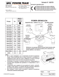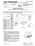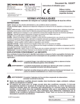
1
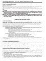
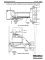
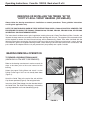
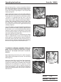
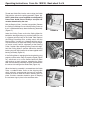
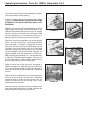
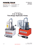
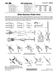
Form No. 102810
®
Operating Instructions for:
SPX Corporation
5885 11th Street
Rockford, IL 61109-3699 USA
Tech. Services: (800) 477-8326
Fax: (800) 765-8326
Order Entry: (800) 541-1418
Fax: (800) 288-7031
Internet Address:
http://www.powerteam.com
PR2100J
PR2100J-50-220
PR2100S
PR3100J
PR3100J-50-380
PR3100S
MODEL C
UNIVERSAL RAILROAD AXLE ROLLER BEARING
PULLER / INSTALLER
Max. Capacity: 100 Tons Pulling
68 Tons Installing
INSTRUCTIONS REQUIRED TO PUT PULLER INTO SERVICE
NOTE: Before operating this puller, carefully follow all the steps given below.
STEP 1. Carefully read and understand the Safety Precautions and Operating Instructions on
form numbers 102810, 102371, 102397, and 100412 attached. These safety
precautions and operating instructions describe general safety precautions and the
method required to connect the pump, hoses, fittings, and pulling cylinder. Since this
puller has been completely assembled and tested at our factory, follow the succeeding
steps to put the puller into service.
STEP 2. Carefully remove all packing materials from the assembled puller.
STEP 3. Fill pump reservoir to proper operating level using approved Power Team hydraulic oil.
STEP 4. Connect pump power cord to proper power source and lower puller cylinder to lowest
position. Start pump and cycle pulling cylinder to full extension, then to full retraction,
three or more times until the cylinder advances and retracts smoothly throughout the
cycle.
STEP 5. Allow the pump to build to full pressure with the cylinder first fully extended, and then
fully retracted. Stop pump and check each hose, fitting, and other system components
for any oil leakage. If any leakage is found, correct the problem and retest.
STEP 6. Install proper tooling on puller and operate puller following the instructions for
"Removing or Installing the Timken 'AP' or 'Hyatt Hy-roll Taper' Bearing (or similar)" as
written on form number 102810 attached.
This page intentionally left blank.
Form No. 102810
®
Operating Instructions for:
SPX Corporation
5885 11th Street
Rockford, IL 61109-3699 USA
Tech. Services: (800) 477-8326
Fax: (800) 765-8326
Order Entry: (800) 541-1418
Fax: (800) 288-7031
Internet Address:
http://www.powerteam.com
PR2100J
PR2100J-50-220
PR2100S
PR3100J
PR3100J-50-380
PR3100S
MODEL C
UNIVERSAL RAILROAD AXLE ROLLER BEARING
PULLER / INSTALLER
Max. Capacity: 100 Tons Pulling
68 Tons Installing
● Carefully inspect the pump upon arrival. The carrier, not the manufacturer, is responsible for any damage
●
resulting from shipment.
These instructions should be read and carefully followed. Most problems with new equipment are caused
by improper operation or installation.
SAFETY PRECAUTIONS
WARNING
● All WARNING statements must be carefully observed to help prevent personal injury. Keep these
instructions at or near the machine location. Only qualified individuals should operate this equipment.
Hydraulic Hose
● Before operating the pump, tighten all hose connections using the proper tools. Do not overtighten the
●
connections. Connections need only be tightened securely and leak-free. Overtightening may cause
premature thread failure or high pressure fittings to split at pressures lower than their rated capacities.
Should a hydraulic hose ever burst, rupture, or need to be disconnected, immediately shut off the pump.
●
Never attempt to grasp a leaking hose under pressure with your hands. The force of the escaping
hydraulic fluid could cause serious injury.
Do not subject the hose to potential hazard such as fire, extreme heat or cold, sharp surfaces, or heavy
impact. Do not allow the hose to kink, twist, curl or bend so tightly that the oil flow within the hose is
blocked or reduced. Periodically inspect the hose for signs of wear because any of these conditions can
damage the hose and may result in personal injury.
Do not use the hose to move attached equipment. Stress may damage the hose and cause personal injury.
●
● Hose material and coupler seals must be compatible with the hydraulic fluid used. Hoses also must not
come in contact with corrosive materials such as creosote-impregnated objects and some paints. Consult
the manufacturer before painting a hose. Never paint the couplers. Hose deterioration due to corrosive
materials may result in personal injury.
Pump
● Do not exceed the PSI hydraulic pressure rating noted on the pump nameplate or tamper with the internal
●
high relief valve. Creating pressures beyond rated capacities may result in personal injury.
Before replenishing the oil level, retract all cylinders to prevent overfilling the pump reservoir. An overfill
may cause personal injury due to excess reservoir pressure created with cylinders are retracted.
© SPX Corporation
Sheet No.
1 of 4
Issue Date:
Rev. 9-1-93
Operating Instructions, Form No. 102810, Back sheet 1 of 4
Safety Precautions (continued)
General Operation
● Do not beat or hammer on or near any part of this unit! Sharp or sudden impacts can cause undue stress
●
on highly loaded parts which can result in equipment damage or possible personal injury.
Stand back as far as the remote control will allow during bearing removal or installation in case of part
breakage.
● A qualified individual should carefully inspect the unit before each use. This individual should look for any
●
abnormal condition that may present a potentially hazardous situation. If any abnormal condition is found,
do not use the equipment until it is corrected and approved for use.
It is the user's responsibility to wear protective equipment as dictated by federal, state or local laws. As a
minimum, it is suggested that the operator and anyone else in the work area, wear safety glasses, safety
shoes, and a hard hat.
OPERATING INSTRUCTIONS
HOSE CONNECTION
IMPORTANT: Seal all hydraulic connections with Power Team HTS6 thread sealant. Teflon tape can be used to
seal hydraulic connections if only one layer of tape is used. Apply carefully, two threads back, to prevent it from being
pinched by the coupler and broken off inside the system. Any loose pieces of tape could travel through the system
and obstruct the flow of oil or cause jamming of precision-fit parts.
Hose connections should be done in the following sequence:
MODELS PR2100J, PR2100J-50-220, PR3100J, & PR3100J-50-380 (refer to illustration on sheet 2 of 4)
The units are supplied completely assembled.
1. Connect one 40 in. hose from port "A" to the pressure regulator valve.
2. Connect the other 40 in. hose from port "B" to the shut-off valve.
3. Operate the unit, with the cylinder in the lowest position, three or more times until it advances and
retracts smoothly.
MODELS PR2100S & PR3100S (refer to illustration on sheet 2 of 4)
1. Connect the 2 ft. hose from port "A" to the pressure regulator valve.
2. Connect the 40 in. hose from port "B" to the shut-off valve.
3. Operate the unit three or more times until it advances and retracts smoothly.
NOTE: If hoses are connected wrong, the remote control switch will operate the cylinder in reverse of what
the decal indicates.
EXTERNAL PRESSURE REGULATOR
The pressure regulator valve allows the operator of the bearing puller / installer to limit the pressure on the return
stroke of the cylinder when the journal axle bearings are being installed.
The pressure regulator valve (#9623) has been set at 6,000 PSI. The maximum force (output) of the cylinder at 6,000
PSI when the piston is being retracted is 40 tons (with the shut-off valve open). If the maximum force of the cylinder is
needed for bearing installation, the shut-off valve should be closed.
Adjusting the Pressure Regulator Valve (Refer to Parts List #101314)
NOTE: For easy adjustment of the pressure regulator valve, always adjust the pressure by INCREASING it to
a desired pressure setting. The pressure range for this unit is 1,000 PSI to 10,000 PSI.
1. Loosen the locknut on the pressure regulator valve. Turn the adjusting screw a few turns counterclockwise (CCW)
to decrease the pressure setting to a lower than desired pressure.
2. Open the shut-off valve.
3. Place the four-way control valve in the RETURN position.
4. Start the pump and build pressure on the return side of the #9623 valve. Slowly turn the adjusting screw in a
clockwise (CW) direction to gradually increase the pressure setting. When the desired pressure setting is reached,
lock the adjusting screw into position by tightening the locknut.
Operating Instructions
Form No. 102810
HYDRAULIC HOSE CONNECTION AND PRESSURE REGULATOR
JACK TYPE PULLER
SLING TYPE PULLER
Sheet No.
2 of 4
Issue Date:
Rev. 9-1-93
Operating Instructions, Form No. 102810, Back sheet 2 of 4
REMOVING OR INSTALLING THE TIMKEN "AP"OR
"HYATT HY-ROLL TAPER" BEARING (OR SIMILAR)
Always follow the bearing manufacturer's installation or removal procedures. These guideline instructions
are for typical application only.
NOTE: THE PHOTOGRAPHS USED IN THESE INSTRUCTIONS SHOW A Y4600-A IN ACTION, HOWEVER, THE
PROCEDURE FOR USING THE PR2100J, PR2100J-50-220, PR2100S, PR3100J, PR3100J-50-380, OR PR3100S
IS IDENTICAL UNLESS OTHERWISE NOTED.
The instructions that follow cover a typical application involving the use of a Power Team Bearing Puller / Installer, and
illustrate the steps necessary to remove and install roller bearings with this unit. The adapters and accessories which
will be required to remove and install these bearings will be determined by Power Team when furnished with the
following information concerning the particular bearing to be serviced: Bearing manufacturer's name; bearing
manufacturer's general arrangement drawing number; size of bearing to be serviced; railroad name and location; and
part number of the adapters which are in your possession if you presently own a puller / installer.
BEARING REMOVAL OPERATION
TO REMOVE A BEARING FROM AN AXLE
(WHEN ONLY A FEW ARE TO BE REMOVED)
Refer to the bearing manufacturer's service manual for
steps to be taken prior to the actual removal of the
bearing.
Select the proper Pulling Shoe and attach it to the
Pulling Frame Legs if this has not already been done
(Figure 1).
FIGURE 1
Attach the Guide Tube to the end of the axle with the
Cap Screws provided (Figure 2). Do not tighten bolts.
Insert the Guide Tube Adapter into the threaded hole in
the Guide Tube. The Guide Tube Adapter is retained by
a spring-loaded ball and is not threaded (Figure 3).
FIGURE 2
FIGURE 3
Operating Instructions
Form No. 102810
Roll the Bearing Puller / Installer into position. Remove
the Pulling Frame Stop Pins and tilt the Pulling Frame so
that it is positioned directly above the Bearing Assembly.
Place the Forcing Plug Adapter in the Piston Rod
Coupling (Figure 4).
Lower the Pulling Frame so that the Pulling Shoe fits
behind the bearing backing ring and replace the Pulling
Frame Stop Pins, making certain that the Bearing Puller
/ Installer is in alignment with the axle. It may be
necessary to adjust the Pulling Frame for height to
assure correct vertical alignment of the Bearing Puller /
Installer. After adjusting Pulling Frame for height, hold
the Pulling Shoe in position behind the bearing backing
ring until initial pressure has been applied to the bearing
assembly (Figure 5).
FIGURE 4
If the Pulling Shoe is engaging the bearing backing ring
properly and the entire setup is properly aligned (Figure
6), stand back as far as the remote control will allow and
continue to apply pressure, extending the Piston Rod
until the bearing assembly has been removed from the
axle and is resting on the Guide Tube.
When the bearing assembly is removed from the Guide
Tube, a cardboard tube, similar to the shipping tube
which originally accompanied the bearing assembly,
should be used to hold the internal bearing parts in
place. Particular attention should be given to keeping
the seal wear rings in place in the enclosure seals.
FIGURE 5
FIGURE 6
TO REMOVE A BEARING ASSEMBLY FROM AN
AXLE (WHEN NUMEROUS BEARING ASSEMBLIES OF THE SAME SIZE ARE TO BE REMOVED)
Upon determining the bearing size, select the proper
Pulling Shoe Insert Adapter and attach it to the Pulling
Shoe (Figure 7).
FIGURE 7
Attach the Guide Tube to the Piston Rod Coupling by
threading the Installing Adapter into the Guide Tube
(Figure 8) and attaching this assembly to the Piston Rod
Coupling with the Connector Pin (Figure 9), making
certain that the Guide Tube is tightened against the
Piston Rod Coupling so that the pressure required to
remove the bearing assembly will not shear or bend the
Connector Pin.
FIGURE 8
FIGURE 9
Sheet No.
3 of 4
Issue Date:
Rev. 9-1-93
Operating Instructions, Form No. 102810, Back sheet 3 of 4
Thread two Guide Pins into the axle to align the Guide
Tube with the axle for the pulling operation (Figure 10).
NOTE: Guide Pins are not supplied or catalogued by
Power Team. Guide Pins are strictly a user part and
must be determined by the user.
Roll the Bearing Puller / Installer into position. Remove
the Pulling Frame Stop Pins and tilt the Pulling Frame so
that it is positioned directly above the Bearing Assembly
(Figure 11).
FIGURE 10
Lower the Pulling Frame so that the Pulling Shoe fits
behind the bearing backing ring and the Guide Pins are
in alignment with the holes in the Guide Tube. Replace
the Pulling Frame Stop Pins, making certain that the
Bearing Puller / Installer is in alignment with the axle. It
may be necessary to adjust the Pulling Frame for height
to assure correct vertical adjustment of the Bearing
Puller / Installer. After adjusting Pulling Frame for height,
hold the Pulling Shoe in position behind the bearing
backing ring until initial pressure has been applied to the
bearing assembly (Figure 12).
If the Pulling Shoe is engaging the bearing backing ring
properly and the entire setup is properly aligned (Figure
13), stand back as far as the remote control will allow
and continue to apply pressure, extending the Piston
Rod until the bearing assembly has been removed from
the axle and is resting on the Guide Tube (Figure 14).
FIGURE 11
FIGURE 12
FIGURE 13
When the bearing assembly is removed from the Guide
Tube, a cardboard tube, similar to the shipping tube
which originally accompanied the bearing assembly,
should be used to hold the internal bearing parts in
place. Particular attention should be given to keeping
the seal wear rings in place in the enclosure seals.
FIGURE 14
Operating Instructions
Form No. 102810
BEARING ASSEMBLY
INSTALLATION OPERATION
The axle should be checked for size and condition
before bearing assemblies are reinstalled. (Check the
bearing manufacturer's service manual for steps and
procedures to be taken in checking the axle.) Any
undesirable conditions such as upset ends, high spots,
or blemishes should be corrected.
TO INSTALL A BEARING ASSEMBLY ON AN
AXLE
Attach the Guide Tube to the end of the axle with the
cap screws provided (Figure 15). If a large number of
bearing assemblies are to be installed, at least two
Guide Tubes should be used to facilitate more efficient
production. NOTE: Do not tighten Guide Tube bolts,
see rule 5.47 of AAR Manual.
FIGURE 15
Thread the Installing Adapter into the Guide Tube
(Figure 16).
Coat the bearing seats of the axle with castor oil, heavy
mineral oil, a Molykote and oil mixture, or as directed by
the bearing manufacturer (Figure 17). NOTE: DO NOT
USE WHITE LEAD. Lead compounds act as an
oxidation catalyst in lubricating greases.
Slip the bearing assembly on the Guide Tube. The seal
wear ring should be held in place to prevent it from
riding out of the enclosure seal when the cardboard tube
is ejected. A small lift is recommended for handling the
larger bearing assembly sizes (Figure 18).
FIGURE 16
FIGURE 17
Place the Installing Tube Adapter Ring in position
against the outer seal wear ring. Make certain that the
Installing Tube Adapter Ring is properly positioned on
the Guide Tube to receive the Installing Tube (Figure
19). MAKE CERTAIN THAT THE INSTALLING TUBE
ADAPTER RING IS NOT REVERSED!
If the Pulling Shoe Inser t Adapter has not been
previously detached from the Pulling Shoe, detach it.
Bearing assembly installation cannot be accomplished
with the Pulling Shoe Insert Adapter attached to the
Pulling Shoe (Figure 20).
FIGURE 18
FIGURE 19
FIGURE 20
Sheet No.
4 of 4
Issue Date:
Rev. 9-1-93
Operating Instructions, Form No. 102810, Back sheet 4 of 4
Place the Installing Tube Cradles between the lower
arms of the Pulling Frame (Figure 21).
Place the Installing Tube on the Installing Tube Cradles
(Figure 22). MAKE CERTAIN THE INSTALLING TUBE
IS FACING IN THE RIGHT DIRECTION AND IS NOT
REVERSED!
Regulate the Installing Tube Cradle Adjusting screws to
properly align the Installing Tube with the recess in the
Hydraulic Ram Mounting Plate so that they will engage
correctly (Figure 23). Normally this adjustment need
only be made once and is not necessary each time a
bearing assembly of the same size is to be installed.
FIGURE 21
FIGURE 22
Extend the Piston Rod completely and roll the Bearing
Puller / Installer into position, adjusting the Pulling
Frame for height, if necessary. Engage the Installing
Tube with the Installing Tube Adapter Ring and the
Threaded Installing Adapter with the Piston Rod
Coupling, making certain that the holes in the Threaded
Installing Adapter and the Piston Rod Coupling are
properly aligned. Insert the Connector Pin (Figure 24).
Before inserting the Connector Pin, it may be necessary
to adjust the Threaded Installing Adapter a few turns so
that the Connector Pin, when inserted, almost touches
the end of the guide slot in the Installing Tube.
FIGURE 23
Begin to retract the Piston Rod and if everything is
properly engaged and aligned (Figure 25), stand back
as far as the remote control will allow and continue to
retract the Piston Rod to press the bearing assembly on
the axle.
Allow the pressure registered on the Pressure gauge to
build up to the bearing manufacturer's suggested
seating tonnage to insure that the bearing parts are
properly seated and that the backing ring is firmly
seated against the axle fillet.
After the bearing assembly has been pressed on the
axle, remove the Bearing Puller / Installer and rotate the
bearing assembly to make sure that it will turn.
FIGURE 24
FIGURE 25