1
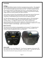
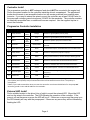
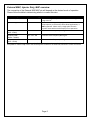
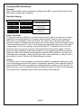
Multi-Input Water/Methanol Injection Controller P/N 30-3305 ! WARNING: Improper installation and/or adjustment of this product can result in major engine/vehicle damage! Use of this injection system requires proper tuning! Use this system with EXTREME caution! If you are uncomfortable with anything about this, please refer the installation to an AEM trained tuning shop or call 800-423-0046 for technical assistance. You should also visit the AEM Performance Electronics Forum at http://www.aempower.com NOTE: AEM holds no responsibility for any engine damage that results from the misuse of this product! This product is legal in California for racing vehicles only and should never be used upon a highway. This product is legal solely for vehicles used in competition which may never be used upon a public road or highway ADVANCED ENGINE MANAGEMENT INC. th 2205 126 Street Unit A, Hawthorne, CA. 90250 Phone: (310) 484-2322 Fax: (310) 484-0152 http://www.aemelectronics.com Instruction Part Number: 10-3305 Rev A 2013 Advanced Engine Management, Inc Page 1 Controller Settings The AEM Water Methanol Injection Controller is a progressive type controller. This means that fluid will be injected in proportion to the amount of boost that is detected by the external MAP input. In other words, higher signal input equals more fluid. It is therefore imperative that the external signal connection be made properly and securely or vehicle/engine damage could occur. In addition, the controller will automatically compensate for any fluctuations in battery voltage variations to ensure consistent flow under all conditions. The two knobs on the face of the controller dictate at what signal input minimum fluid injection starts and at what signal input maximum/full fluid injection occurs. Fluid injection will ‘progressively’ increase between these two points as set by the adjustment knobs. The “Start” dial has a range from 0% (full counterclockwise rotation) to 100% (full clockwise rotation). The “Full” dial has a range of 0% (full counterclockwise rotation) to 100% (full clockwise rotation). It is suggested to adjust the “Start” value by setting the dial to approximately 25% of the vehicles maximum signal input. Adjust the full-in value to your maximum possible percent for signal input. These are only suggestions; improper use or setting could result in engine or vehicle damage -- please consult your tuner. Mode Selection The mode can only be selected or changed while the unit is turned off. To change the mode remove the back cover exposing the three DIP switch selectors. Follow the guide on the controller to select the appropriate mode for your application. Status LED The controller has an on-board Status LED. This will mimic the operation of the external LED. Upon startup the current mode is flashed in green on the status LED. It will flash error codes in red as well as illuminate with varying intensity as a function of flow in green. Page 2 Fuse The controller has an externally accessible fuse. The controller itself will turn on and function, but the pump will not run without the fuse. If the controller is reporting an open circuit it may be that the fuse has blown, and or is not installed correctly. Use a 15 amp fast blow fuse for replacement purposes. “Test” Button The Test button feature is available to test the systems functionality. This feature should be used ONLY with the nozzle disconnected from the engine. This is to prevent unintentional pumping of fluid into the engine. To operate the test button press and hold. The pump speed will gradually increase from zero to full speed over 3 seconds, and then remain full for another 3 seconds before stopping. Flow should begin gradually and then hold at full pressure for a total test time of 6 seconds. Short circuit self-diagnostics There are two modes of pump-driver short circuit protection available. One can detect a short at any time but produces a slight buzzing in the pump. This should not be noticeable under most conditions, but can be turned off if it is objectionable. If turned off, a short circuit can only be detected when the pump is running. To enable or disable this diagnostic (and the buzzing): Press and hold the “Test” button while applying power to the controller. The change is acknowledged by a single long flash of the status LED output and the external LED. Once the button is released the controller will continue to function normally. You can also tell what mode has been selected by listening for the buzzing sound in the pump. Repeating this operation will toggle between the two modes. Page 3 Controller Install The progressive controller is NOT waterproof and should NOT be mounted in the engine bay! Find a convenient location for the controller inside the driver’s compartment. The adjustment knobs should remain in an accessible location but still remain protected from possible water incursion. If you need to extend the wires to mount the controller use at least 16 AWG wire for the pump and controller ground circuits and 18 AWG for the remainder. The controller contains an externally accessible fuse, no additional fuses are required. Use the supplied zip-ties to mount the controller. Progressive Controller Installation Pin # Description 1 Pump Ground 2 LED - 3 LED + 4 Solenoid - 5 Boost Safe LS Out 6 Pump Power 7 Ground 8 Level Switch+ 9 Level Switch- 10 Arm Switch + 11 External Signal 12 Power 12V Wire** 16 AWG 20 AWG 20 AWG 20 AWG 18 AWG 16 AWG 16 AWG 20 AWG 20 AWG 20 AWG 18 AWG 16 AWG Color Orange Connection Connect to ground (black) wire of pump. Gray Connect to ground (black) wire of external LED. Violet Connect to positive (red) wire of external LED. Brown/White Green 1.5A Low Side output. Connect to optional flow control solenoid. 1.7A Low Side output. Grounded when error condition exists. Pink Connect to the positive (red) wire of pump. Black Main ground connection, connect directly to battery ground. White Connect to the white wire of the fluid tank level sensor* Brown Connect to the black wire of the fluid tank level sensor* Yellow Arms injection system. Connect to a switched 12V source. Blue Red Connect to External Signal. (0-5V, injector duty, MAF frequency) Main Power Connection, connect directly to positive battery terminal. *Note: If fluid tank is equipped with previous generation level sensor, identified by having two black wires, then pins 8 (white) and 9 (brown) may be connected to either of the two black sensor wires. The polarity is unimportant. **Note: If you need to extend the wires to mount the controller use at least 16 AWG wire for the pump and controller ground circuits and 18 AWG for the remainder. External LED Install Find a suitable location in the driver’s line of sight to mount the external LED. Mount the LED and run the wires to the controller. The LED indicates the operation of the controller. If the pump is off and there are no errors the LED will be off. If there are no errors and the pump is on the LED intensity will vary with the pump speed. If there are any errors they will be indicated by flashing the LED. Page 4 External MAP, Injector Duty, MAF overview The connection of the External MAP/MAF pin will depend on the desired mode of operation. Please follow the table in determining where to connect this wire. Mode of operation MAF / MAP (0V-5V) Dip Switch Settings ON – ON – ON Injector Duty (0%-100%) OFF – OFF – ON Frequency MAF (40Hz - 220Hz) Frequency MAF (400Hz – 2200Hz) Frequency MAF (2kHz – 14kHz) OFF – ON – OFF Pin Installation location *Connect to signal output from MAF/MAP where signal range is 0V-5V. *Connect to the injector duty signal that is active low. MultiPulse Injection, as is found on some diesel applications, is NOT supported. Please verify a single pulse for each injection event with an oscilloscope prior to operation. *Connect to the frequency MAF signal. OFF – ON – ON *Connect to the frequency MAF signal. ON – OFF – OFF *Connect to the frequency MAF signal. *Please consult the factory service manual to find the appropriate wire to tap for the above connections. It is acceptable to make this tap close to the sensor/injector or nearer to the ECU itself; whichever is more convenient. Page 5 External MAP 0-5V Installation Operation: The 0 – 5 Volt external MAP mode is designed for vehicles running high boost, beyond that of the Internal and HD models, or for users who already have a sensor or output of their MAP with a range of 0 – 5 Volts. See Table 1 for compatible AEM MAP sensors. Dip Switch Settings: ON – ON – ON Setup, Connection: To setup your system for external MAP you must first find the correct source to connect to. In order to locate the correct signal the use of a volt meter will be required. Once you have located your MAP sensor you can begin to check the wires for the “signal” wire. The signal wire should remain at or near 0 Volts when the car is turned off or is not running. Once the vehicle is started it should continue to remain at or near 0, however it may begin oscillate up and down slightly. To determine if you do in fact have the correct wire you can try and rev the engine while monitoring the voltage. You should observe the signal rising and falling with engine speed. Please note that you may need to rev the engine high enough to put it into boost. Once you have found the correct signal wire you may tap onto it (if it is used by other devices), or connect it directly to the Water Methanol controller (Pin #11 – Blue). Testing: To test your setup it is recommended you finish the installation, but before installing the nozzle you run the engine and ensure the system is operating as expected. That is when the engine is running and the MAP sensor is outputting in a range set by the controller you will get flow. You want to ensure you are not getting flow when the engine is turned off or is not expected. This could be due to improper wiring or the incorrect mode selected. Pressure Range AEM Brass Sensor Kit P/N AEM Stainless Steel Sensor Kit P/N 1 Bar / 15PSIa 30-2131-15G 30-2130-15 2 Bar / 30 PSIa 30-2131-30 30-2130-30 3.5 Bar / 50 PSIa 30-2131-50 30-2130-50 5 Bar / 75 PSIa 30-2131-75 30-2130-75 100 PSIg 30-2131-100 30-2130-100 Table 1 – Compatible AEM Pressure Sensor Kits Page 6 Injector Duty Installation Operation: The Injector Duty mode is designed for vehicles where water methanol injection rate is desired to be highly coupled to the injector duty, meaning the more fuel the more water methanol. This mode can be used when MAF is not available, or in NA vehicles. Injector duty is NOT intended to work with diesel or other multi-pulse injection systems. Dip Switch Settings: OFF – OFF – ON Setup, Connection: To setup your system for injector duty you must first find the correct signal wire to connect too. You must locate and tap onto one of the two wires going to the fuel injector. One of the wires will be switched +12V (typically red) and the other will be the desired signal wire from the ECU. Using a voltmeter you can determine if you have the correct signal by watching the voltage as the engine is running. As duty cycle increases and more fuel injected, the measured DC voltage will appear lower as viewed on a voltmeter. If you have an oscilloscope or a way to measure duty cycle this is even better. Once you are sure you have the correct signal you can tap on to the signal and connect that to pin #11 (blue wire) on the controller. Testing: To test your setup it is recommended you finish the installation, but before installing the nozzle you run the engine and ensure the system is operating as expected. That is when the engine is running you want to ensure you are not getting flow when the engine is turned off or is not expected. This could be due to improper wiring or the incorrect mode selected. Page 7 0-5V MAF Installation Operation: The 0 – 5 Volt MAF mode is designed for vehicles where MAF is used and the output of their MAF sensor is 0-5V and not a frequency. Dip Switch Settings: Mode DIP Switches Common Applications 0 - 5 Volt ON – ON – ON VW/Audi 1.8T Subaru WRX/STi Nissan S13/S14/S15/300ZX Setup, Connection: To setup your system for MAF you must first find the correct source to connect too. In order to locate the correct signal the use of a voltmeter will be required. Once you have located your MAF sensor you can begin to check the wires for the “signal” wire. The signal wire should remain at or near 0 Volts when the car is turned off or is not running. Once the vehicle is started it should continue to remain at or near 0, however it may begin oscillate up and down slightly. To determine if you do in fact have the correct wire you can try and rev the engine while monitoring the voltage. If the signal rises and falls with the engine speed then you have likely identified the correct wire. If you are experiencing difficulty locating the signal wire, refer to the vehicle’s service manual to locate the MAF signal wire, and then try to verify again with a voltmeter. Once you have found the correct signal wire you may tap onto and connect it to pin #11 (blue) of the Water Methanol controller. Testing: To test your setup it is recommended you finish the installation, but before installing the nozzle you run the engine and ensure the system is operating as expected. That is when the engine is running and the MAF sensor is outputting in a range set by the controller you will get flow. You want to ensure you are not getting flow when the engine is turned off or when it is not expected. This could be due to improper wiring or having the incorrect mode selected. Page 8 Frequency MAF Installation Operation: The Frequency MAF mode is designed for vehicles where MAF is used and the output of their MAF sensor is digital and a frequency. Dip Switch Settings: Mode Frequency MAF (40Hz - 220Hz) Frequency MAF (400Hz – 2200Hz) Frequency MAF (2kHz – 14kHz) DIP Switches Common Applications OFF – ON – OFF 1993 and older GM OFF – ON – ON ON – OFF – OFF 1990 – 1999 Mitsu 1G/2G DSM 1994+ GM VW 2.0T, etc Setup, Connection: To setup your system for MAF you must first find the correct source to connect too. In order to locate the correct signal the use of a voltmeter will be required. Once you have located your MAF sensor you can begin to check the wires for the “signal” wire. The signal wire should remain at or near 0 Volts when the car is turned off or is not running. Once the vehicle is started it should remain at or near 2.5 Volts. This is because the signal has a duty cycle of 50% and a voltage range of 0-5V so the average voltage will be about ½. To determine if you do in fact have the correct wire you can try and rev the engine while monitoring the voltage. It should remain the same regardless of the engine speed; if you are experiencing difficulty locating the signal wire, refer to the vehicles service manual to locate the MAF signal wire, and then try to verify again with a voltmeter. Once you have found the correct signal wire you may tap onto it and connect it to pin #11 (blue) of the Water Methanol controller. Testing: To test your setup it is recommended you finish the installation, but before installing the nozzle you run the engine and ensure the system is operating as expected. That is when the engine is running and the MAF sensor is outputting in a range set by the controller you will get flow. You want to ensure you are not getting flow when the engine is turned off or when it is not expected. This could be due to improper wiring or having the incorrect mode selected. Page 9 Optional System Upgrades Water/Methanol Injection FAILSAFE Device AEM P/N 30-3020/30-3020M Actively monitors the entire flow curve independent of pressure, continuously collecting flow vs. injection rate data so that any deviation from your established flow curve will trigger an alarm output that can be used to reduce boost or timing, change maps, add fuel, trigger a two-step or perform practically any action you choose to save your engine. It is PC programmable (with USB connectivity) which eliminates the guesswork when setting min/max threshold parameters. HIGHLY RECOMMENDED for all water/methanol injection systems Water/Methanol Injection Flow Gauge – AEM P/N 30-5141/30-5142 Displays flow rate data on a smooth moving needle-type gauge that allows you to accurately monitor the status of your injection system in real time. Available in max flow rates of 500 cc/min or 1000 cc/min with a black or white face. The AEM water/methanol injection filter is HIGHLY RECOMMENDED when using this flow gauge. Water/Methanol Injection Filter – AEM P/N 30-3003 Inline filter that uses a micronic mesh screen to filter out particles as small as 40 microns. Allows a cleaner flow of water/methanol into the injection pump, lines, and nozzles increasing overall system longevity. Injection filter is HIGHLY RECOMMENDED when using the AEM water/methanol injection flow gauge. Additional Nozzle Kit – AEM P/N 30-3012 Includes one nozzle body, two jet sizes, and the necessary hardware to run a second nozzle in your injection system. 5 Gallon Tank – AEM P/N 30-3010 Upgrade to a 5 gallon tank to maximize your fluid holding capacity. Includes level sensor and mounting hardware. Page 10 AEM Electronics warranty Advanced Engine Management Inc. warrants to the consumer that all AEM High Performance products will be free from defects in material and workmanship for a period of twelve (12) months from date of the original purchase. Products that fail within this 12-month warranty period will be repaired or replaced at AEM’s option, when determined by AEM that the product failed due to defects in material or workmanship. This warranty is limited to the repair or replacement of the AEM part. In no event shall this warranty exceed the original purchase price of the AEM part nor shall AEM be responsible for special, incidental or consequential damages or cost incurred due to the failure of this product. Warranty claims to AEM must be transportation prepaid and accompanied with dated proof of purchase. This warranty applies only to the original purchaser of product and is non-transferable. All implied warranties shall be limited in duration to the said 12-month warranty period. Improper use or installation, accident, abuse, unauthorized repairs or alterations voids this warranty. AEM disclaims any liability for consequential damages due to breach of any written or implied warranty on all products manufactured by AEM. Warranty returns will only be accepted by AEM when accompanied by a valid Return Merchandise Authorization (RMA) number. Product must be received by AEM within 30 days of the date the RMA is issued. Please note that before AEM can issue an RMA for any electronic product, it is first necessary for the installer or end user to contact the EMS tech line at 1-800-423-0046 to discuss the problem. Most issues can be resolved over the phone. Under no circumstances should a system be returned or a RMA requested before the above process transpires. AEM will not be responsible for electronic products that are installed incorrectly, installed in a non-approved application, misused, or tampered with. Any AEM electronics product can be returned for repair if it is out of the warranty period. There is a minimum charge of $50.00 for inspection and diagnosis of AEM electronic parts. Parts used in the repair of AEM electronic components will be extra. AEM will provide an estimate of repairs and receive written or electronic authorization before repairs are made to the product. Page 11