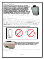
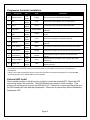
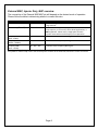
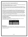
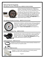
1
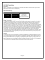
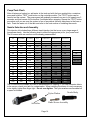
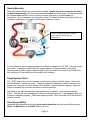
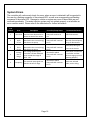
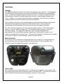
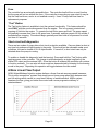
Multi-Input Water/Methanol Injection Kit P/N 30-3350, 30-3351 ! WARNING: Improper installation and/or adjustment of this product can result in major engine/vehicle damage! Use of this injection system requires proper tuning! Use this system with EXTREME caution! If you are uncomfortable with anything about this, please refer the installation to an AEM trained tuning shop or call 800-423-0046 for technical assistance. You should also visit the AEM Performance Electronics Forum at http://www.aempower.com NOTE: AEM holds no responsibility for any engine damage that results from the misuse of this product! This product is legal in California for racing vehicles only and should never be used upon a highway. This product is legal solely for vehicles used in competition which may never be used upon a public road or highway ADVANCED ENGINE MANAGEMENT INC. th 2205 126 Street Unit A, Hawthorne, CA. 90250 Phone: (310) 484-2322 Fax: (310) 484-0152 http://www.aemelectronics.com Instruction Part Number: 10-3350 Rev A 2013 Advanced Engine Management, Inc Page 1 Contents Introduction ...................................................................................................................................3 Specifications ...............................................................................................................................3 Hardware Kit: ............................................................................................................................3 Parts List: ..................................................................................................................................3 Injector Nozzle Kit: ....................................................................................................................3 Installation ....................................................................................................................................4 Diagram ....................................................................................................................................4 Installation Checklist .................................................................................................................5 Pump and Tank Install ..............................................................................................................6 Controller Install ........................................................................................................................7 Progressive Controller Installation.............................................................................................8 External LED Install...................................................................................................................8 External MAP, Injector Duty, MAF overview .............................................................................9 External MAP 0-5V Installation................................................................................................10 Injector Duty Installation ..........................................................................................................11 0-5V MAF Installation ..............................................................................................................12 Frequency MAF Installation ....................................................................................................13 Pump/Tank Flush ....................................................................................................................14 Nozzle Selection and Assembly ..............................................................................................14 Nozzle Mounting .....................................................................................................................15 Pump/System Check...............................................................................................................15 Fluid Compatibility ...................................................................................................................15 System Errors .............................................................................................................................16 Troubleshooting Diagram ........................................................................................................17 Controller ....................................................................................................................................18 Settings ...................................................................................................................................18 Mode Selection .......................................................................................................................18 Status LED ..............................................................................................................................18 Fuse ........................................................................................................................................19 “Test” Button ...........................................................................................................................19 Short circuit self-diagnostics ...................................................................................................19 A More Linear Flow Output .........................................................................................................19 Boost-Safe Output (optional) ......................................................................................................20 Solenoid Driver (optional) ...........................................................................................................20 Non-Progressive Operation (optional) ........................................................................................20 Engine Tuning ............................................................................................................................20 Important Safety Notice Regarding Methanol .............................................................................21 Cold Weather Operation .............................................................................................................21 Maintenance ...............................................................................................................................21 Optional System Upgrades .........................................................................................................22 AEM Electronics warranty ...........................................................................................................23 Page 2 Introduction Congratulations on your purchase of the AEM Water/Methanol Injection Kit. This document will help guide you through the setup and installation process. Please take the time to review its contents prior to installation. Pay especially close attention to any bolded text, as it indicates an important note, or step in the process. Before beginning installation of electronic components please disconnect the ground side of the battery. This is for your safety. Specifications 1 Gallon tank with integral level sensor 200 PSI injection pump Progressive pump controller with “Boost Safe” feature High amperage pump driver with over-current, over-voltage and under-voltage protection Error protection output with over-current, over-voltage and over-temperature protection Two system status LED indicators; shows pump duty cycle and system errors Pump open and short detection and indication; works even if the pump is off Test button that manually triggers pump Two dial pump speed control Hardware Kit: Parts List: Quantity 20 ft 1 Description High Pressure ¼” Nylon Hose 1 Gallon Tank With Integral Fluid Level Sensor 10”h x 8.5”w x 4.25”d 1 200 PSI Pump With Integral Fittings 1 1 Progressive Injection Module 12 ft Wiring Harness Injector Nozzle Kit: Quantity 1 1 1 1 1 1 Description Jet, Medium (500 cc/min) Jet, Small (250 cc/min) Jet, Large (1000 cc/min) Nylon Washer Injector Body H2O Nozzle Part # 35-4500-20 35-4542 5843-2S0DB744AM 35-4551 35-3451 35-4546 Part # 35-4514-02 35-4514-04 35-4514-05 35-4517 35-4515-2 35-4545 Quantity 36 in 6 in 1 10 4 4 8 4 4 4 12 4 4 4 1 2 9 4 1 Page 3 Description 3/8" High Temp Wire Wrap Edge Protector 1/8” Tee Fitting 6” Zip Tie Bolt, Hex Head, 5/16-18 x 1.25” Bolt, Hex Head, 8-32 x 1.5” Screw, Pan Head #8 x 1.0" Screw, Pan Head #6 x 0.5" Nut, Nylock, 5/16-18 Nut, Nylock, 8-32 Washer, #8 x 3/4" Washer, #8 x 7/16" Washer, 5/16 Washer, Fender, 5/16 5mm Cockpit LED Butt Connector, 14-16 AWG (blue) Butt Connector, 18-22 AWG (red) Ring Terminal, 14-16 AWD (blue) 1/4" Hose Routing Strip 35-4512HW Part # 8-169 8-111-E 35-2147 8-113-E 1-2115 1-2116 1-3048 1-3049 1-3055 1-2537 1-3051 1-3050 1-3031-E 1-3054 35-4505 8-360 8-361 8-354 35-4500-20 Installation Diagram NOTE: THIS KIT INCLUDES NEW STYLE INJECTOR NOZZLES THAT HAVE INTERNAL CHECK VALVES. AN EXTERNAL CHECK IS NO LONGER NEEDED OR INCLUDED IN THIS KIT. Page 4 Installation Checklist The following list of steps is an overview of the installation process. A complete and more detailed list of each step including optional peripherals is defined later in this document. □ Install Tank o Fasten with 4 of the 8 supplied #8 sheet metal screws along with the 4 large washers or the 5/16-18 bolts and Nylock nuts. □ Install Pump o Select suitable location for pump near and below the lowest fluid level of tank. o Fasten with 4 of the #8 sheet metal screws along with the 4 small washers or the #8-32 bolts and Nylock nuts. o Cut supplied nylon hose with a sharp razor blade and install from tank to pump. □ Install Controller o Disconnect ground side of battery during electronic installation. o Find suitable location for controller inside driver’s compartment. o Find location in driver’s field of view and install external LED. o Follow the wire diagram and connect wires from supplied wire harness. o Connect the blue wire to external input signal □ Flush Tank o Connect the remainder of hose to pump. (DO NOT CONNECT NOZZLE) o Fill Tank with Water (AEM recommends using Distilled Water). o Turn on key power to power on controller. o Use Test button on controller to flush the tank into a separate container. o Drain tank and proceed to next step. □ Connect Nozzle to System o Select nozzle and connect to nylon hose. o Fill tank with Water. o Use Test button on controller to test complete system. □ System Check o While pushing the Test button ensure that no errors are reported and that the system is producing a gradually increasing flow out of the nozzle. o This may require pressing the Test button multiple times to purge the system. o Drain tank and fill with desired Water/methanol mixture. o DO NOT use a hydrocarbon fuel. Water/Methanol are the only supported fluids □ Install Nozzle o Find a suitable location to install nozzle. Nozzle must be mounted before the throttle plate. Nozzle should also be mounted after the MAF sensor if present. Nozzle must also be mounted after any intercoolers. o Install nozzle, follow instructions for modifying intake to accept the nozzle. o Cut and install nylon hose from pump to nozzle. Ensure that the hose is not resting, near, or running on any moving or “hot” parts. □ Tune Engine o Engine tuning is usually required in order to maximize potential power gain. Page 5 Pump and Tank Install Find a suitable location to mount the tank and pump. The tank should be mounted such that it is below the injection point. The tank and pump must be mounted in the same area. Pump may be mounted on exterior of vehicle but should be mounted away from wheel wells or other areas where it will come into direct contact with water or road debris. Pump failures that have clearly been caused by exposure to water/mud/debris will not be covered under warranty. This includes but is not limited to, the bed of a truck, and the inside of the fender wells. Find a location where the pump will remain dry. Use 4 of the 8 supplied #8 sheet metal screws along with the 4 large washers or the 5/16-18 bolts and Nylock nuts to mount the 1gallon tank. (Optional 5 Gallon Tank Install) Before mounting the tank, check the area under the desired mounting location for fuel tanks, fuel lines, or any other obstructions. Mount the tank in an upright level position as shown below. Mark the four mounting points and drill with a 3/8” bit. Use the supplied 5/16-18 bolts, nuts, and large OD flat washers for mounting the tank into your vehicle. IMPORTANT: Use the supplied large OD washer to spread the load on the plastic mounting ears of the tank. DO NOT OVERTIGHTEN! Nuts should just be snug; they are locking nuts and will not loosen. Overtightening will crack the plastic and cause leaks and void the warranty. Note: All tanks are tested for leaks during assembly. A special sealant adhesive is used to bond the plastic tank to the metal fitting. DO NOT attempt to tighten the fitting any further! The pump must be located in the same area as the tank and should be mounted at or below the lowest fluid level height. Page 6 Take note of the direction of flow, indicated by the arrows on the pump body, when mounting the pump. Use four #8 sheet metal screws along with the 4 small washers or the #8-32 bolts and nylock nuts to mount the pump. The pump can be mounted in any position horizontally or vertically. Once the tank and pump are mounted, cut the appropriate length of tubing needed to connect the outlet fitting on the tank to the inlet fitting on the pump. Make sure there are no sharp bends in the tubing. Cut the tubing to length with a clean perpendicular slice using a sharp razor blade, making sure the ends are clean and square. Push in the hose at the tank and pump to install. Make sure they are pushed in all the way and check with a light tug on the hose. Secure the hose to the chassis using sections of the supplied hose routing strip or with zip-ties. Controller Install The progressive controller is NOT waterproof and should NOT be mounted in the engine bay! Find a convenient location for the controller inside the driver’s compartment. The adjustment knobs should remain in an accessible location but still remain protected from possible water incursion. If you need to extend the wires to mount the controller use at least 16 AWG wire for the pump and controller ground circuits and 18 AWG for the remainder. The controller contains an externally accessible fuse, no additional fuses are required. Use the supplied zip-ties to mount the controller. Page 7 Progressive Controller Installation Pin # Description Wire** Color Connection 16 Orange Connect to ground (black) wire of pump. AWG 20 2 LED Gray Connect to ground (black) wire of external LED. AWG 20 3 LED + Violet Connect to positive (red) wire of external LED. AWG 20 1.5A Low Side output. Connect to optional flow control 4 Solenoid Brown/White AWG solenoid. Boost Safe LS 18 1.7A Low Side output. Grounded when error condition 5 Green Out AWG exists. 16 6 Pump Power Pink Connect to the positive (red) wire of pump. AWG 16 Main ground connection, connect directly to battery 7 Ground Black AWG ground. 20 8 Level Switch+ White Connect to the white wire of the fluid tank level sensor* AWG 20 9 Level SwitchBrown Connect to the black wire of the fluid tank level sensor* AWG 20 Arms injection system. Connect to a switched 12V 10 Arm Switch + Yellow AWG source. 18 Connect to External Signal. (0-5V, injector duty, MAF 11 External Signal Blue AWG frequency) 16 Main Power Connection, connect directly to positive 12 Power 12V Red AWG battery terminal. *Note: If fluid tank is equipped with previous generation level sensor, identified by having two black wires, then pins 8 (white) and 9 (brown) may be connected to either of the two black sensor wires. The polarity is unimportant. **Note: If you need to extend the wires to mount the controller use at least 16 AWG wire for the pump and controller ground circuits and 18 AWG for the remainder. 1 Pump Ground External LED Install Find a suitable location in the driver’s line of sight to mount the external LED. Mount the LED and run the wires to the controller. The LED indicates the operation of the controller. If the pump is off and there are no errors the LED will be off. If there are no errors and the pump is on the LED intensity will vary with the pump speed. If there are any errors they will be indicated by flashing the LED. Page 8 External MAP, Injector Duty, MAF overview The connection of the External MAP/MAF pin will depend on the desired mode of operation. Please follow the table in determining where to connect this wire. Mode of operation MAF / MAP (0V-5V) Dip Switch Settings ON – ON – ON Injector Duty (0%-100%) OFF – OFF – ON Frequency MAF (40Hz - 220Hz) Frequency MAF (400Hz – 2200Hz) Frequency MAF (2kHz – 14kHz) OFF – ON – OFF Pin Installation location *Connect to signal output from MAF/MAP where signal range is 0V-5V. *Connect to the injector duty signal that is active low. MultiPulse Injection, as is found on some diesel applications, is NOT supported. Please verify a single pulse for each injection event with an oscilloscope prior to operation. *Connect to the frequency MAF signal. OFF – ON – ON *Connect to the frequency MAF signal. ON – OFF – OFF *Connect to the frequency MAF signal. *Please consult the factory service manual to find the appropriate wire to tap for the above connections. It is acceptable to make this tap close to the sensor/injector or nearer to the ECU itself; whichever is more convenient. Page 9 External MAP 0-5V Installation Operation: The 0 – 5 Volt external MAP mode is designed for vehicles running high boost, beyond that of the Internal and HD models, or for users who already have a sensor or output of their MAP with a range of 0 – 5 Volts. See Table 1 for compatible AEM MAP sensors. Dip Switch Settings: ON – ON – ON Setup, Connection: To setup your system for external MAP you must first find the correct source to connect to. In order to locate the correct signal the use of a volt meter will be required. Once you have located your MAP sensor you can begin to check the wires for the “signal” wire. The signal wire should remain at or near 0 Volts when the car is turned off or is not running. Once the vehicle is started it should continue to remain at or near 0, however it may begin oscillate up and down slightly. To determine if you do in fact have the correct wire you can try and rev the engine while monitoring the voltage. You should observe the signal rising and falling with engine speed. Please note that you may need to rev the engine high enough to put it into boost. Once you have found the correct signal wire you may tap onto it (if it is used by other devices), or connect it directly to the Water Methanol controller (Pin #11 – Blue). Testing: To test your setup it is recommended you finish the installation, but before installing the nozzle you run the engine and ensure the system is operating as expected. That is when the engine is running and the MAP sensor is outputting in a range set by the controller you will get flow. You want to ensure you are not getting flow when the engine is turned off or is not expected. This could be due to improper wiring or the incorrect mode selected. Pressure Range AEM Brass Sensor Kit P/N AEM Stainless Steel Sensor Kit P/N 1 Bar / 15PSIa 30-2131-15G 30-2130-15 2 Bar / 30 PSIa 30-2131-30 30-2130-30 3.5 Bar / 50 PSIa 30-2131-50 30-2130-50 5 Bar / 75 PSIa 30-2131-75 30-2130-75 100 PSIg 30-2131-100 30-2130-100 Table 1 – Compatible AEM Pressure Sensor Kits Page 10 Injector Duty Installation Operation: The Injector Duty mode is designed for vehicles where water methanol injection rate is desired to be highly coupled to the injector duty, meaning the more fuel the more water methanol. This mode can be used when MAF is not available, or in NA vehicles. Injector duty is NOT intended to work with diesel or other multi-pulse injection systems. Dip Switch Settings: OFF – OFF – ON Setup, Connection: To setup your system for injector duty you must first find the correct signal wire to connect too. You must locate and tap onto one of the two wires going to the fuel injector. One of the wires will be switched +12V (typically red) and the other will be the desired signal wire from the ECU. Using a voltmeter you can determine if you have the correct signal by watching the voltage as the engine is running. As duty cycle increases and more fuel injected, the measured DC voltage will appear lower as viewed on a voltmeter. If you have an oscilloscope or a way to measure duty cycle this is even better. Once you are sure you have the correct signal you can tap on to the signal and connect that to pin #11 (blue wire) on the controller. Testing: To test your setup it is recommended you finish the installation, but before installing the nozzle you run the engine and ensure the system is operating as expected. That is when the engine is running you want to ensure you are not getting flow when the engine is turned off or is not expected. This could be due to improper wiring or the incorrect mode selected. Page 11 0-5V MAF Installation Operation: The 0 – 5 Volt MAF mode is designed for vehicles where MAF is used and the output of their MAF sensor is 0-5V and not a frequency. Dip Switch Settings: Mode DIP Switches Common Applications 0 - 5 Volt ON – ON – ON VW/Audi 1.8T Subaru WRX/STi Nissan S13/S14/S15/300ZX Setup, Connection: To setup your system for MAF you must first find the correct source to connect too. In order to locate the correct signal the use of a voltmeter will be required. Once you have located your MAF sensor you can begin to check the wires for the “signal” wire. The signal wire should remain at or near 0 Volts when the car is turned off or is not running. Once the vehicle is started it should continue to remain at or near 0, however it may begin oscillate up and down slightly. To determine if you do in fact have the correct wire you can try and rev the engine while monitoring the voltage. If the signal rises and falls with the engine speed then you have likely identified the correct wire. If you are experiencing difficulty locating the signal wire, refer to the vehicle’s service manual to locate the MAF signal wire, and then try to verify again with a voltmeter. Once you have found the correct signal wire you may tap onto and connect it to pin #11 (blue) of the Water Methanol controller. Testing: To test your setup it is recommended you finish the installation, but before installing the nozzle you run the engine and ensure the system is operating as expected. That is when the engine is running and the MAF sensor is outputting in a range set by the controller you will get flow. You want to ensure you are not getting flow when the engine is turned off or when it is not expected. This could be due to improper wiring or having the incorrect mode selected. Page 12 Frequency MAF Installation Operation: The Frequency MAF mode is designed for vehicles where MAF is used and the output of their MAF sensor is digital and a frequency. Dip Switch Settings: Mode Frequency MAF (40Hz - 220Hz) Frequency MAF (400Hz – 2200Hz) Frequency MAF (2kHz – 14kHz) DIP Switches Common Applications OFF – ON – OFF 1993 and older GM OFF – ON – ON ON – OFF – OFF 1990 – 1999 Mitsu 1G/2G DSM 1994+ GM VW 2.0T, etc Setup, Connection: To setup your system for MAF you must first find the correct source to connect too. In order to locate the correct signal the use of a voltmeter will be required. Once you have located your MAF sensor you can begin to check the wires for the “signal” wire. The signal wire should remain at or near 0 Volts when the car is turned off or is not running. Once the vehicle is started it should remain at or near 2.5 Volts. This is because the signal has a duty cycle of 50% and a voltage range of 0-5V so the average voltage will be about ½. To determine if you do in fact have the correct wire you can try and rev the engine while monitoring the voltage. It should remain the same regardless of the engine speed; if you are experiencing difficulty locating the signal wire, refer to the vehicles service manual to locate the MAF signal wire, and then try to verify again with a voltmeter. Once you have found the correct signal wire you may tap onto it and connect it to pin #11 (blue) of the Water Methanol controller. Testing: To test your setup it is recommended you finish the installation, but before installing the nozzle you run the engine and ensure the system is operating as expected. That is when the engine is running and the MAF sensor is outputting in a range set by the controller you will get flow. You want to ensure you are not getting flow when the engine is turned off or when it is not expected. This could be due to improper wiring or having the incorrect mode selected. Page 13 Pump/Tank Flush After all wires are hooked up, add water to the tank and with the hose pointed into a container, press and hold the “TEST” push button on the controller module. The “TEST” button can be used to test the system. The pump speed will gradually increase from zero to full speed over 3 seconds, and then remain full for another 3 seconds before stopping. Repeat the “TEST” button procedure until you are sure the system is free of any debris that may have been in the lines or tank. Drain the water out of the tank and refer to the next section on installing the nozzle. Nozzle Selection and Assembly This injection kit includes three different sized injection jets that cover a very large range of horsepower levels. Use the following chart to select the appropriate jet for your power level. The kit comes with one medium nozzle already preassembled. Fuel Flow N/A (.5 BSFC) Fuel Flow F/I (.7 BSFC) W/M Flow N/A W/M Flow 5-10psi Boost W/M Flow 10-25psi Boost W/M Flow 25+psi Boost 150 788 200 1050 1101 95 220 275 330 1469 126 294 367 441 250 1313 1836 158 367 459 551 300 1575 2203 189 441 551 661 350 1838 2570 221 514 642 771 Nozzle 400 2100 2937 252 587 734 881 250 450 2363 3304 284 661 826 991 500 500 2625 3671 315 734 918 1101 1000 550 2888 4038 347 808 1010 1212 1000 + 500 600 3150 4406 378 881 1101 1322 1000 + 1000 650 3413 4773 410 955 1193 1432 700 3675 5140 441 1028 1285 1542 750 3938 5507 473 1101 1377 1652 800 4200 5874 504 1175 1469 1762 850 4463 6241 536 1248 1560 1872 900 4725 6608 567 1322 1652 1983 950 4988 6976 599 1395 1744 2093 1000 5250 7343 630 1469 1836 2203 HP The nozzles are serviceable and can be disassembled for cleaning. If you find excessive debris in the screen, check your tank for contamination. When installing the screen it is only necessary to be slightly tighter than finger tight. Do not over-tighten. The nylon washers are reusable but a spare is included. Nylon Washer Nozzle Body Pintle/Screen Assembly Jet/Orifice Page 14 Nozzle Mounting Select the location where the nozzle will be installed. Nozzle should be mounted such that it is higher than the tank. Nozzle must be mounted before the throttle plate. Nozzle should also be mounted after the MAF sensor if present. Nozzle must also be mounted after any intercoolers. In most instances, mounting the nozzle 6-8” ahead of the throttle body provides an excellent combination of air charge cooling and combustion control. Nozzle installed before the throttle plate, after the MAF and any intercoolers. In most instances, the air charge piping can be drilled and tapped for 1/8” NPT to directly mount the nozzle. If using thin walled tubing it’s suggested that a bung be welded to the piping. Mounting hole should be tapped deep enough to allow the end of the nozzle to be nearly flush with the interior of the intake once the nozzle is fully installed. Pump/System Check The “TEST” push button on the controller module can be used to test the system. Press and hold the button to activate the pump. The pump speed will gradually increase from zero to full speed over 3 seconds, and then remain full for another 3 seconds before stopping. When the button is released the controller will return to normal operation. Add water to the tank and with the nozzle pointed into a container, press and hold the test button. The flow will start gradually and increase to a steady amount. If this happens then your system is connected properly. Check and repair any leaks. Drain the water out of the tank and install the nozzle. Fluid Compatibility Under NO circumstances should any hydrocarbon based fuel ever be used with this system. Water and Methanol are the ONLY fluids to be used. Page 15 System Errors The controller will continuously check for errors; when an error is detected it will be reported to the user by a flashing sequence of the external LED, as well as a corresponding red flashing sequence of the status LED. Damage to vehicle or engine may occur if these faults are not resolved immediately. The water-injection system may not operate properly or at all while an error condition exists. Please refer to the table below for further information. # of Flashes Error 1 Low Fluid 2 3 Pump Open Circuit Pump Short Circuit 4 Voltage Out of Range 5 Frequency Description The amount of fluid in the tank has been detected to be below the level of the sensor. An open circuit has been detected in the circuit (wiring) that drives the pump. A short circuit has been detected in the circuit (wiring) that drives the pump. The voltage powering the controller has been detected to be outside the range of 8.5V - 16V. The external input signal was found to be out of range. Controller/Pump Status - BoostSafe Enabled - Pump will continue to run - BoostSafe Enabled - Pump will NOT continue to run - BoostSafe Enabled - Pump will NOT continue to run Recommended Action Refill fluid reservoir. Check for a blown controller fuse and pump wiring for disconnects. Check pump wiring for shorts to the chassis. - BoostSafe Enabled - Pump will NOT continue to run Check power connections to controller and that vehicle charging system is operating properly. - BoostSafe Enabled - Pump will NOT continue to run Check user selected mode, and or wiring. Page 16 Troubleshooting Diagram Page 17 Controller Settings The AEM Water Methanol Injection Controller is a progressive type controller. This means that fluid will be injected in proportion to the amount of boost that is detected by the external MAP input. In other words, higher signal input equals more fluid. It is therefore imperative that the external signal connection be made properly and securely or vehicle/engine damage could occur. In addition, the controller will automatically compensate for any fluctuations in battery voltage variations to ensure consistent flow under all conditions. The two knobs on the face of the controller dictate at what signal input minimum fluid injection starts and at what signal input maximum/full fluid injection occurs. Fluid injection will ‘progressively’ increase between these two points as set by the adjustment knobs. The “Start” dial has a range from 0% (full counterclockwise rotation) to 100% (full clockwise rotation). The “Full” dial has a range of 0% (full counterclockwise rotation) to 100% (full clockwise rotation). It is suggested to adjust the “Start” value by setting the dial to approximately 25% of the vehicles maximum signal input. Adjust the full-in value to your maximum possible percent for signal input. These are only suggestions; improper use or setting could result in engine or vehicle damage -- please consult your tuner. Mode Selection The mode can only be selected or changed while the unit is turned off. To change the mode remove the back cover exposing the three DIP switch selectors. Follow the guide on the controller to select the appropriate mode for your application. Status LED The controller has an on-board Status LED. This will mimic the operation of the external LED. Upon startup the current mode is flashed in green on the status LED. It will flash error codes in red as well as illuminate with varying intensity as a function of flow in green. Page 18 Fuse The controller has an externally accessible fuse. The controller itself will turn on and function, but the pump will not run without the fuse. If the controller is reporting an open circuit it may be that the fuse has blown, and or is not installed correctly. Use a 15 amp fast blow fuse for replacement purposes. “Test” Button The Test button feature is available to test the systems functionality. This feature should be used ONLY with the nozzle disconnected from the engine. This is to prevent unintentional pumping of fluid into the engine. To operate the test button press and hold. The pump speed will gradually increase from zero to full speed over 3 seconds, and then remain full for another 3 seconds before stopping. Flow should begin gradually and then hold at full pressure for a total test time of 6 seconds. Short circuit self-diagnostics There are two modes of pump-driver short circuit protection available. One can detect a short at any time but produces a slight buzzing in the pump. This should not be noticeable under most conditions, but can be turned off if it is objectionable. If turned off, a short circuit can only be detected when the pump is running. To enable or disable this diagnostic (and the buzzing): Press and hold the “Test” button while applying power to the controller. The change is acknowledged by a single long flash of the status LED output and the external LED. Once the button is released the controller will continue to function normally. You can also tell what mode has been selected by listening for the buzzing sound in the pump. Repeating this operation will toggle between the two modes. A More Linear Flow Output AEM’s Water/Methanol Injection system delivers a linear flow rate as pump speed increases. This is unlike competitors’ systems that simply have a linear pump speed drive between start and full settings which results in a non-linear delivery of water/methanol. AEM’s system linearizes the flow, giving you better flow control and a more progressive delivery of water/methanol. Page 19 Boost-Safe Output (optional) The progressive controller includes a Boost-Safe output (grounded when active) that activates whenever the system is armed and runs out of fluid or an error code is flashing. The green wire on the controller is the 1.7 amp switched ground. This wire can be hooked up to a solenoid that will vent waste gate pressure when activated. Apply 12v to the other side of the solenoid (AEM P/N 30-2400 or equivalent). This output can also be used to trigger a timing retard function in a standalone ECU or a CDI whenever the system runs out of fluid, thus protecting your engine. It is highly recommended that this feature be utilized. Solenoid Driver (optional) The progressive controller includes a Solenoid output (Brown with White strip wire grounded when active, 1.5A max) that activates whenever the system is pumping. The wire should be connected to the ground side of a solenoid, with the other end of the solenoid connected to switched ignition power. The solenoid should be installed after the pump and before the nozzle. For best results install the solenoid close to the nozzle. Non-Progressive Operation (optional) The progressive controller is capable of operating in a non-progressive manner, acting as a full on or full off type system. To set this up the “Full PSI” knob must be set to a lower value then the “Start PSI” knob. This means as soon as the boost exceeds the “Start PSI” threshold the pump will begin pumping at its maximum flow since it has passed both the start and the full requirements. Engine Tuning Water/methanol injection is generally not considered a bolt-on power adder for forced induction gasoline applications. Engine tuning is usually required in order to maximize potential power gain. Water/methanol injection allows for a more aggressive tune to be used while still using pump gas as your base fuel. With conservative boost and timing, establish a base AFR that is one point higher than your final target AFR. For example, if your final target AFR with water/methanol injection is 11.0:1, set your base AFR to 12.0:1. Once the base AFR has been set, start injecting water/methanol and adjust the injection flow rate to achieve your final target AFR. For example, if before injection your base AFR is 12.0:1 and then during injection your AFR drops to 10.5:1, reduce the water/methanol flow rate until your final target AFR is reached. It is generally recommended that the flow rate of the injection system be changed in order to reach your target AFR and NOT your primary fueling. Injection flow rate adjustments can be made by changing your nozzle selection or by adjusting the “Start PSI” and “Full PSI” settings. Once the injection flow rate is set to deliver your desired final AFR, boost and ignition timing can be increased to take advantage of the additional air charge cooling and detonation control. When injecting the correct amount, a 50/50 mix of water/methanol has been shown to provide an effective octane of over 110 when using a base fuel of 91-93 octane pump gas. A properly tuned water/methanol injection system will usually support a typical “race gas” engine tune. Page 20 Important Safety Notice Regarding Methanol AEM strongly recommends that users never exceed a 50% methanol concentration when using any AEM Water Methanol system or component. All AEM water/methanol injection systems and components (pump, lines, fittings, filter, flow sensor, tank, and nozzles) are 100% chemically compatible with methanol. However, for safety reasons we strongly recommend that users never use more than a 50% methanol concentration in our systems. Methanol is a toxic and highly flammable chemical. 100% Methanol ignites easily and burns vigorously with an almost undetectable flame. Methanol can be absorbed through the skin and even small amounts can cause blindness or even death. Using this fluid at high pressures, without dilution, in an under-hood environment with nylon lines and push-to-connect fittings is very unsafe. The performance advantages of using greater than 50% methanol concentrations are small, if they exist at all. However, the safety issues are very real and far outweigh any perceived benefit of running high concentrations of methanol. Note: AEM holds no responsibility for any engine damage or personal injury that results from the misuse of this product, including but not limited to injury or death caused by the mishandling of methanol. Cold Weather Operation A Water/Methanol mix will also lower the freezing point of the fluid. Below is a chart with freezing points for different percentages of water/methanol mixtures. Temperature 20 deg F 0 deg F -15 deg F -40 deg F Methanol Concentration % by volume 13 24 35 46 Maintenance The injector nozzle should be cleaned periodically. Disassemble the nozzle and clean it with a suitable cleaner until all debris is removed. If excessive contamination is found check the rest of the system for the source. Page 21 Optional System Upgrades Water/Methanol Injection FAILSAFE Device AEM P/N 30-3020/30-3020M Actively monitors the entire flow curve independent of pressure, continuously collecting flow vs. injection rate data so that any deviation from your established flow curve will trigger an alarm output that can be used to reduce boost or timing, change maps, add fuel, trigger a two-step or perform practically any action you choose to save your engine. It is PC programmable (with USB connectivity) which eliminates the guesswork when setting min/max threshold parameters. HIGHLY RECOMMENDED for all water/methanol injection systems Water/Methanol Injection Flow Gauge – AEM P/N 30-5141/30-5142 Displays flow rate data on a smooth moving needle-type gauge that allows you to accurately monitor the status of your injection system in real time. Available in max flow rates of 500 cc/min or 1000 cc/min with a black or white face. The AEM water/methanol injection filter is HIGHLY RECOMMENDED when using this flow gauge. Water/Methanol Injection Filter – AEM P/N 30-3003 Inline filter that uses a micronic mesh screen to filter out particles as small as 40 microns. Allows a cleaner flow of water/methanol into the injection pump, lines, and nozzles increasing overall system longevity. Injection filter is HIGHLY RECOMMENDED when using the AEM water/methanol injection flow gauge. Additional Nozzle Kit – AEM P/N 30-3012 Includes one nozzle body, two jet sizes, and the necessary hardware to run a second nozzle in your injection system. 5 Gallon Tank – AEM P/N 30-3010 Upgrade to a 5 gallon tank to maximize your fluid holding capacity. Includes level sensor and mounting hardware. Page 22 AEM Electronics warranty Advanced Engine Management Inc. warrants to the consumer that all AEM High Performance products will be free from defects in material and workmanship for a period of twelve (12) months from date of the original purchase. Products that fail within this 12-month warranty period will be repaired or replaced at AEM’s option, when determined by AEM that the product failed due to defects in material or workmanship. This warranty is limited to the repair or replacement of the AEM part. In no event shall this warranty exceed the original purchase price of the AEM part nor shall AEM be responsible for special, incidental or consequential damages or cost incurred due to the failure of this product. Warranty claims to AEM must be transportation prepaid and accompanied with dated proof of purchase. This warranty applies only to the original purchaser of product and is non-transferable. All implied warranties shall be limited in duration to the said 12-month warranty period. Improper use or installation, accident, abuse, unauthorized repairs or alterations voids this warranty. AEM disclaims any liability for consequential damages due to breach of any written or implied warranty on all products manufactured by AEM. Warranty returns will only be accepted by AEM when accompanied by a valid Return Merchandise Authorization (RMA) number. Product must be received by AEM within 30 days of the date the RMA is issued. Please note that before AEM can issue an RMA for any electronic product, it is first necessary for the installer or end user to contact the EMS tech line at 1-800-423-0046 to discuss the problem. Most issues can be resolved over the phone. Under no circumstances should a system be returned or a RMA requested before the above process transpires. AEM will not be responsible for electronic products that are installed incorrectly, installed in a non-approved application, misused, or tampered with. Any AEM electronics product can be returned for repair if it is out of the warranty period. There is a minimum charge of $50.00 for inspection and diagnosis of AEM electronic parts. Parts used in the repair of AEM electronic components will be extra. AEM will provide an estimate of repairs and receive written or electronic authorization before repairs are made to the product. Page 23