1
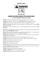
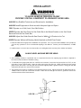
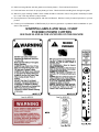
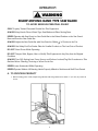
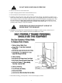
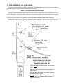
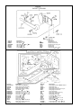
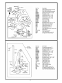
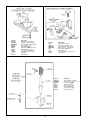
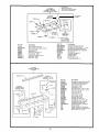
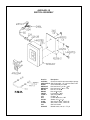
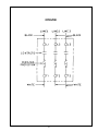
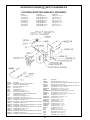
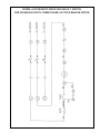
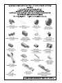
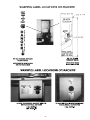
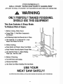
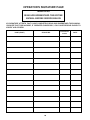
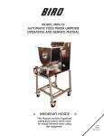
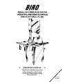
+
IMPORTANT NOTICE
+
This Manual contains important
safety instructions which must
be strictly followed when using
this equipment.
PTCT Md 44
105-7-08-20
105-9-05-18
TABLE OF CONTENTS
Page
NOTICE TO OWNERS AND OPERATORS . . . . . . . . . . . . . . . . . . . . . . . . . . . . . . . . . . . . . . . . . 1
SAFETY TIPS . . . . . . . . . . . . . . . . . . . . . . . . . . . . . . . . . . . . . . . . . . . . . . . . . . . . . . . . . . . . . . . 2
INSTALLATION . . . . . . . . . . . . . . . . . . . . . . . . . . . . . . . . . . . . . . . . . . . . . . . . . . . . . . . . . . . . 3-5
OPERATION . . . . . . . . . . . . . . . . . . . . . . . . . . . . . . . . . . . . . . . . . . . . . . . . . . . . . . . . . . . . . . . . 6
TO PROCESS PRODUCT . . . . . . . . . . . . . . . . . . . . . . . . . . . . . . . . . . . . . . . . . . . . . . . 6-7
CLEANING . . . . . . . . . . . . . . . . . . . . . . . . . . . . . . . . . . . . . . . . . . . . . . . . . . . . . . . . . . . . . . . . . 8
MAINTENANCE . . . . . . . . . . . . . . . . . . . . . . . . . . . . . . . . . . . . . . . . . . . . . . . . . . . . . . . . . . . . . 9
GENERAL . . . . . . . . . . . . . . . . . . . . . . . . . . . . . . . . . . . . . . . . . . . . . . . . . . . . . . . . . . . . 9
LUBRICATION . . . . . . . . . . . . . . . . . . . . . . . . . . . . . . . . . . . . . . . . . . . . . . . . . . . . . . . . . 10
SAW GUIDE BAR AND SAW GUARD . . . . . . . . . . . . . . . . . . . . . . . . . . . . . . . . . . . . . . . . 11
PARTS DIAGRAMS . . . . . . . . . . . . . . . . . . . . . . . . . . . . . . . . . . . . . . . . . . . . . . . . . . . . . . . . 12-19
SWITCH ASSEMBLIES AND SERVICE PARTS . . . . . . . . . . . . . . . . . . . . . . . . . . . . . . . . . . 20 & 22
WIRING DIAGRAMS . . . . . . . . . . . . . . . . . . . . . . . . . . . . . . . . . . . . . . . . . . . . . . . . . . . . . . 21 & 23
WEARABLE SAW PARTS LISTING . . . . . . . . . . . . . . . . . . . . . . . . . . . . . . . . . . . . . . . . . . . . . . . 24
PARTS LIST/ORDERING. . . . . . . . . . . . . . . . . . . . . . . . . . . . . . . . . . . . . . . . . . . . . . . . . . . . . . . 25
PARTS ASSEMBLIES LIST/ORDERING . . . . . . . . . . . . . . . . . . . . . . . . . . . . . . . . . . . . . . . . . . . 26
WARNING LABEL LOCATIONS ON MACHINE . . . . . . . . . . . . . . . . . . . . . . . . . . . . . . . . . . . . . . 27
OPERATOR'S
PAGE. .. . . . . . . . . . . . . . . . . . . . . . . . . . . . . . . . . . . . . . . . . . . . . . . . 28
WALL
CHARTSIGNATURE
(PART NO. 671)
OPERATOR'S NOTE
PAGE. PAGE
. . . . . . . . . . . . . . . . . . . . . . . . . . . . . . . . . . . . . . . . . . . . . . . . . . . . 29
OPERATOR’S
SIGNATURE
LIMITED WARRANTY . . . . . . . . . . . . . . . . . . . . . . . . . . . . . . . . . . . . . . . . . . . . . . . . . . . . . . . . . 30
NOTICE TO OWNERS AND OPERATORS
BIRO’s products are designed to process food products safely and efficiently. Unless the operator is properly trained and supervised, there is the possibility of a serious injury. It is the responsibility of the owner to assure that this machine is used properly and safely, strictly following the
instructions contained in this Manual and any requirements of local law.
No one should use or service this machine without proper training and supervision. All operators should be thoroughly familiar with the procedures contained in this Manual. Even so BIRO
cannot anticipate every circumstance or environment in which its products will be used. You, the
owner and operator, must remain alert to the hazards posed by the function of this equipment –
particularly the SHARP MOVING BAND TYPE SAW BLADE. No one under eighteen (18) years of
age should operate this equipment. If you are uncertain about a particular task, ask your supervisor.
This Manual contains a number of safe practices in the SAFETY TIP section. Additional warnings are placed throughout the Manual. Warnings related to your personal safety are indicated by:
OR
Warnings related to possible damage are indicated by:
BIRO also has provided a wall chart to be posted near the equipment. If any warning label, wall
chart, or Manual becomes misplaced, damaged, or illegible, please contact your nearest Distributor or BIRO directly for a replacement.
Remember, however, this Manual or the warning labels do not replace the need to be alert and
to use your common sense when using this equipment.
This Manual applies to machines with serial number 3850 and higher, except where noted.
– NOTE –
A copy of this manual is included with each MODEL 44 POWER SAW.
The descriptions and illustrations contained in this manual are not binding.
The manufacturer reserves the right to introduce any modification without
updating the manual.
1
SAFETY TIPS
SHARP MOVING BAND TYPE SAW BLADE
TO AVOID SERIOUS PERSONAL INJURY
NEVER Touch This Machine Without Training and Authorization By Your Supervisor.
ALWAYS Read Operation and Service Manual BEFORE Operating, Cleaning or Servicing.
ALWAYS Keep Hands Clear of Sharp Band Type Saw Blade and Other Moving Parts.
ONLY Use a Qualified Electrician to Install According to Local Building Codes: Machine MUST
Be Properly Grounded.
ONLY Install on Level, Non-Skid Surface in a Clean Well-Lighted Work Area Away from Children
and Visitors.
DO NOT Attempt to Operate This Machine Until it has Been Inspected and Demonstrated by the
Seller – Recognized BIRO Representative.
DO NOT Alter or Modify This Machine in any Way From its Original Form. This Machine in its
Original Form Meets the Intent of O.S.H.A. Applicable Standards.
NEVER Operate with Saw Guard on Saw Guide Bar in the Raised Position or the Saw Guard Removed from the Saw Guide Bar.
ALWAYS Adjust Saw Guide Bar with Saw Guard to Within 1 2" of Product to be Cut.
ALWAYS Use Safety End Cut Pusher Plate for Smaller Products or the Last Cuts of Product.
DO NOT Use This Machine for Non-Food Products.
DO NOT Use This Machine to Cut Pigs Feet.
DO NOT Wear Gloves While Operating.
ALWAYS Turn Off, Unplug From Power Source and Perform Lockout/Tagout Procedure to This
Machine BEFORE Removing Shrouds, Removable Guards, Cover, Doors, Fences or Panels for
Cleaning, Servicing or any Other Reason.
NEVER Leave Machine Unattended While Operating.
PROMPTLY REPLACE Any Worn or Illegible Warning Labels.
USE ONLY BIRO Parts and Accessories Properly Installed.
2
INSTALLATION
TO AVOID SERIOUS PERSONAL INJURY
PROPERLY INSTALL EQUIPMENT IN ADEQUATE WORK AREA
ALWAYS Use Qualified Technician and Electrician for Installation.
ALWAYS Install Equipment in Work area with Adequate Light and Space.
ONLY Operate on a Solid, Level, Non-Skid Surface.
NEVER Operate with Saw Guard on Saw Guide Bar in the Raised Position or the Saw Guard
Removed from the Saw Guide Bar.
ALWAYS Adjust Saw Guide Bar with Saw Guard to Within 1 2" of Product to be Cut.
NEVER Operate Without all Warning Labels Attached and Wall Chart Posted.
1. Read this Manual thoroughly before installation and operation. Do not proceed with installation and operation if
you have any questions or do not understand anything in this Manual. Contact your local Distributor, or BIRO
first.
2. Install machine on a level, solid, non-skid surface in a well-lighted work area away from children and visitors.
ALWAYS LEVEL MACHINE BEFORE USING
3. After installing machine in operational area, it is imperative that the four adjusting leg hex bolts be adjusted to
level the machine and also to eliminate rocking.
4. To assemble meat gauge plate (Part No. A18275) to the machine; Loosen the lock knob (Part No. 272-7) on the
right side of meat gauge bracket. Raise the meat gauge gear rack (Part No. 18272) and slip the meat gauge
plate over the gear rack. Lower the gear rack back to its original position, tighten lock knob. Keep gear rack well
oiled with food grade oil to ensure free movement.
5. The head structure (Part No. S18005) comes detached from the base. Slip the head into the slide gibs (Part No.
18260) located on the back of the base structure. Make sure the slide gibs are oiled or greased to ensure free
vertical movement of the head structure.
3
6. Place removable finger lift with saw guard assembly (Part No. A18211) on the saw guide bar (Part No. 116-27)
and fasten in place with finger lift fastener knob (Part No. 211A-291Q).
SHARP SAW BLADE. HANDLE WITH EXTREME CAUTION.
7. Placing blade on cutter: Hang upper wheel assembly (Part No. A18003U335) on the hinge bracket (Part No.
71-2). Lift the nylon filler (Part No. 177). Hang blade on the upper wheel and hold with right hand. With left
hand force the back of the blade between the front blade cleaners (Part No. 131), located below the nylon filler.
Lower the nylon filler and insert the back of the blade in the upper saw guide (Part No. 602B). The blade has already dropped over the lower wheel. With right hand force the back of the blade between the rear blade cleaners
(Part No. 131). The blade is now ready to be tightened. Press down on the ratchet arm (Part No. 18010) located
at the rear of the base structure. Turn the upper wheel slowly by hand to ensure proper tracking of the saw blade
on the wheels. Tighten to proper tension. When the tension gauge (Part No. 18197), located at the bottom rear
of the head becomes tight laterally the blade is at proper tension.
8. The stationary platter (Part No. A18163) is placed on top of the base structure and held in place by two push-pull
hold down rods (Part No. 18212W), located at the back of the base structure.
9. The sliding meat carriage assembly (Part No. A18155EZ) is installed by turning the movable stop assembly (Part
No. A16200) clockwise. After the carriage assembly is in the channel for operation, turn the movable stop counterclockwise to lock.
10. Post SAFETY TIPS wall chart within easy view of operator. Keep Manual available to operator.
11. Machine MUST be properly grounded. Use qualified electrician to install according to building codes.
WIRING MOTOR
(1) Interchange of motor current is made in motor outlet box. Leads are properly marked. Changing
instructions are on motor plate or motor outlet box.
(2) All cutters are wired 220 volts unless otherwise specified. Be sure motor specifications (voltage, cycle, phase)
match power supply line. Be sure line voltage is up to specification.
(3) Connect leads to machine in a manner that will be approved by local electrical inspectors.
(4) We recommend no less than No. 12 wire. If the leads are too light, machine may not have sufficient cutting
power and/or speed.
(5) The V-belt is packed loose in machine to prevent deformation, and must be installed on pulleys at time of
wiring motor.
(6) The BIRO Manufacturing Company is not responsible for permanent wiring, connection or installation.
NOTE TO OWNER AND ELECTRICIAN: IF THIS MACHINE IS NOT CORD
AND PLUG CONNECTED TO THE ELECTRICAL SUPPLY SOURCE, THEN IT
SHOULD BE EQUIPPED WITH, OR CONNECTED TO, A LOCKABLE,
MANUALLY OPERATED DISCONNECT SWITCH (OSHA 1010.147).
KEEP HANDS CLEAR OF SHARP MOVING BAND TYPE SAW
BLADE.
4
12. Make sure saw guide bar with saw guard is in its lowest position. Close head and base doors.
13. Push start button and check for proper phasing of motor. Blade should be travelling down through saw guide.
14. Watch for proper tracking of blade. Back of blade should be centered in hole in saw guide in stationary bar (Part
No. 119A). Push stop button to stop machine.
15. Check placement of all warning labels, wall chart and Manual. Machine is ready for trained operators to process
product.
16. Contact your local Distributor or BIRO directly if you have any questions or problems with the installation or operation of this machine.
WARNING LABELS AND WALL CHART
FOR BIRO POWER CUTTERS
SEE PAGE 25 AND 26 FOR LOCATIONS ON THIS MACHINE
5
OPERATION
SHARP MOVING BAND TYPE SAW BLADE
TO AVOID SERIOUS PERSONAL INJURY
ONLY Properly Trained Personnel Should Use This Equipment.
ALWAYS Keep Hands Clear of Band Type Saw Blade and Other Moving Parts.
NEVER Operate with Saw Guard on Saw Guide Bar in the Raised Position or the Saw Guard
Removed from the Saw Guide Bar.
ALWAYS Adjust the Saw Guide Bar with Saw Guard to Within 1 2" of Product to be Cut.
ALWAYS Use Safety End Cut Pusher Plate for Smaller Products or The Last Cuts of Product.
DO NOT Wear Gloves While Operating.
DO NOT Tamper With, Bypass, Alter or Modify This Equipment in Any Way from its Original
Condition.
ALWAYS Turn Off, Unplug from Power Source and Perform Lockout/Tag Out Procedures to This
Machine Before Cleaning, Servicing or When Not in Use.
NEVER Leave Unattended While Operating.
NEVER Operate Without All Warning Labels Properly Affixed to Machine and Wall Chart Posted.
A. TO PROCESS PRODUCT
1. Before starting power cutter, adjust saw guide bar with saw guard down to within ½² (13 mm) of product to
be cut.
6
DO NOT WEAR GLOVES WHILE OPERATING
2. Make sure all doors are closed and locked.
3. Ajdust meat gauge plate forward to desired thickness of cut.
4. Push start button and watch blade for proper tracking.
5. Standing in front of the power cutter, place product on the meat carriage. Pay attention to position of your
hands. Keep hands clear of moving band type saw blade. Leaning lightly against the scalloped front edge of
meat carriage, hold the product firmly in right hand with product face flush against meat gauge plate. Move
the meat carriage from right to left at a steady rate until fully past the saw blade. Use left hand to remove
and stack cut product, NEVER REACH IN FRONT OF BAND TYPE SAW BLADE. On the return stroke,
pull the product toward you, away from saw blade.
NEVER REACH OR GRAB FOR PRODUCT IN FRONT OF
MOVING BAND TYPE SAW BLADE
6. ALWAYS use the safety End Cut Pusher Plate (Part No. 256P) for smaller products or the last cuts of
product. The pusher plate is supplied as standard on all BIRO power cutters.
7. When finished cutting, push stop button. Perform lockout/tagout procedure.
7
CLEANING
SHARP MOVING BAND TYPE SAW BLADE
TO AVOID SERIOUS PERSONAL INJURY
ALWAYS Turn Off, Unplug From Power Source and Perform Lockout/Tagout Procedure to This
Machine BEFORE Cleaning or Servicing.
ONLY Use Recommended Cleaning Equipment, Materials and Procedures.
NEVER Spray Water or Other Liquid Substances Directly at Motor, Power Switch or any Other
Electrical Components.
ALWAYS Thoroughly Clean Equipment at Least Daily.
CLEANING THE BIRO POWER CUTTER:
Disconnect electrical power to the machine before cleaning. Parts to be removed have been made accessible and can
be removed without tools. Notice in the drawing below that all parts are numbered. Each part should be removed for
cleaning in the numbered sequence shown. To ensure cleaner cuts, keep the parts on the cleaning system in good
condition. Parts on the cleaning system which should be checked weekly, and changed as required are as follows:
Wheel Cleaners (Part No. 179), Saw Cleaners (Part No. 131), Saw Guide in Stationary Bar (Part No. 119A), Upper Saw
Guide (Part No. 602B), Lower Blade Back-Up Guide (Part No. 605) and Nylon Filler (Part No. 177).
8
MAINTENANCE
SHARP MOVING BAND TYPE SAW BLADE
TO AVOID SERIOUS PERSONAL INJURY
ALWAYS Turn Off, Unplug From Power Source and Perform Lockout/Tag Out Procedure to This
Machine BEFORE Cleaning or Servicing.
NEVER Touch This Machine Without Training and Authorization By Your Supervisor.
ALWAYS Keep Hands Clear of Band Type Saw Blade and Other Moving Parts.
NEVER Bypass, Alter, or Modify This Equipment in Any Way From Its Original Condition.
PROMPTLY REPLACE Any Worn or Illegible Warning Labels.
USE ONLY GENUINE BIRO Parts and Accessories Properly Installed.
A. GENERAL
MACHINE SHOULD BE GENERALLY INSPECTED EVERY TIME
IT IS CLEANED (AT LEAST DAILY) TO ENSURE THAT IT IS IN
GOOD CONDITION AND HAS NOT BEEN DAMAGED OR
TAMPERED WITH
A. SAW WHEELS: Clean outer diameter grooves daily. Check for cracks, gouges or wear on the flange and
grooves.
DO NOT IMMERSE UPPER WHEEL
ASSEMBLY IN WATER
B. WHEEL CLEANER ASSEMBLIES: Check condition of fiber cleaner, change every four (4) weeks.
C. REMOVABLE FINGER LIFT ASSEMBLY: Check condition of saw guard, make sure mounting bolts are
tight and the “DANGER EXPOSED BLADE” decal is affixed and legible. Check condition of upper saw guide
(Part No. 602B), replace every six (6) months. Check adjustment of upper saw guide. Should be 1 32"
between back of blade and saw guide carbide.
NEVER USE THIS MACHINE WITHOUT PROPERLY INSTALLED
AND FUNCTIONING SAW GUIDE BAR AND SAW GUARD
D. SAW GUIDE BAR: Check condition of bar for coating peeling and wear, replace as necessary. Check saw
guide bar spring for proper tension. The spring should hold the bar in any desired position in its travel.
Replace saw guide bar spring (Part No. 193) as necessary using instructions below.
1.
2.
3.
4.
5.
6.
7.
8.
9.
Remove the finger lift fastener knob and the fingerlift assembly.
Remove the finger lift fastener stud.
Push the saw guide bar up and out of the top of the head structure.
Remove the saw guide bar spring.
Clean and lubricate the babbitt pocket area (the square indented area that seats the saw
guide bar spring).
Lower the new saw guide bar spring through the top of the babbitt pocket area and guide
the spring into position with a standard screwdriver. (NOTE: Drawing)
While holding the saw guide bar spring in position, re-enter the saw guide bar from the top
compressing the saw guide bar spring slightly until the saw guide bar slides past the
spring.
Replace the finger lift fastener stud, the finger lift assembly and the finger lift fastener knob.
Test by making several adjustments.
9
E. STATIONARY BAR ASSEMBLY: Check condition of nylon filler (Part No. 177), change every four (4) weeks.
Check condition of saw guide (Part No. 119A), check tracking of blade through guide, back of blade should
be centered in hole, replace every six (6) months. Check condition of lower blade back-up guide (Part No.
605). Check adjustment of back-up guide, should have 1 32² gap between back of blade and saw guide
carbide. Replace every six (6) months.
F. SAW CLEANERS: Check condition of blade cleaners, replace every four (4) weeks.
G. RATCHET ASSEMBLY: Check for smooth operation through full range of travel. Check condition of trigger
spring, replace as necessary.
H. SLIDE GIBS: Check that the head structure moves freely up and down. Check for side to side and fore to
aft tolerance. Adjust as required. Grease every four (4) weeks.
I. MEAT GAUGE ASSEMBLY: Check free movement of meat gauge plate on gear rack. Gear rack to be kept
lubricated at all times with light food grade oil. Check operation of release handle. Check that worm gear
engages properly with gear rack.
J. MEAT CARRIAGE ASSEMBLY: Check for free movement through full range of travel. Check for side to
side tolerance, adjust as necessary. Check condition of bearings, replace as necessary. Check condition of
thumb guard, replace as necessary.
K. SAFETY ITEMS: Safety end cut pusher plate is with machine and accessible. All warning labels are present,
properly affixed and legible. Model and Serial Number plate properly affixed and legible. Wall poster within
operator’s view from machine. Manual accessible to operator.
B. LUBRICATION
1. UPPER WHEEL BEARINGS: Grease every four (4) months. Change grease every
twelve (12) months.
2. LOWER BEARING HOUSING: Grease
every four (4) months. Change grease every twelve (12) months.
3. SLIDE GIBS:
Grease every four (4)
weeks.
4. MEAT CARRIAGE BEARINGS: Grease
every four (4) weeks.
5. SAW GUIDE BAR: Oil daily with food
machine oil.
6. MEAT GAUGE GEAR RACK: Oil daily
with food machine oil.
When lubricating the upper wheel bearing it is important that the three hex head
screws securing the upper wheel hub cap be loosened slightly before attempting to
pump grease into the grease fitting. Loosening the screws allows for an escape of
old broken down grease and air from the bearing cavity. Failure to loosen the screws
before greasing the upper bearings can cause the upper shaft seal to be dislodged
from the upper wheel allowing grease to escape and moisture to get into the cavity.
When finished greasing the bearings, retighten the three screws. Take care to also
clean off any grease that was pushed out of the cavity during greasing.
7. MOTOR BEARINGS –– Bearing grease will lose its lubricating ability over time, not suddenly. The lubricating
ability of a grease (over time) depends primarily on the type of grease, the size of the bearing, the speed at which
the bearing operates and the severity of the operating conditions. Good results can be obtained if the following
recommendations are used in your maintenance program.
A high grade ball or roller bearing grease should be used. Recommended grease for standard service conditions
is Polyrex EM (Exxon Mobil).
Equivalent and compatible greases include:
Texaco Polystar, Rykon Premium #2, Pennzoil Pen 2 Lube, and Chevorn SRI.
Recommended lubrications intervals is every 9 months with the equivalent of two (2) teaspoons of grease.
10
C. SAW GUIDE BAR AND SAW GUARD
The factory recommends that when service is performed on any BIRO SAW the servicing agency be sure that the
BIRO SAW is equipped with the most current safety features available.
MODEL 44 SAW GUIDE BARS AND SAW GUARDS
Production of the BIRO Model 44 began March 1956. All units prior to serial #4511 were equipped with a (round)
cast aluminum head. The saw guide bar measured 21½² and the (Item #255) SAW GUARD was the same as used
on Models 33 and 34.
The factory recommends that on all units equipped with (round) cast aluminum heads, the complete head
assembly be replaced with the current stainless steel (fabricated square) HEAD ASSEMBLY (Item #AS18005).
All units serial #4511 on were built with a fabricated (square) steel head. The saw guide bar on these units
measured 27² and is current. All units serial #4511 on are equipped with the most current safety features.
INSTRUCTIONS FOR ATTACHING
NEW GUARD FOR USE WITH
EXTENDED SAW GUIDE BAR
• Remove head door and lay inside up, placing new
guard inside door face and flange as shown in diagram.
• Drill upper hole first; clamp guard tight against inside of door.
• Then drill lower flange hole, using hole in guard as
a locator for the lower bolt.
• Notice: Care must be taken to position edges parallel so that the old standard guard will slide up inside the new guard.
11
12
13
14P
Item No.
A16112
AS18005
AS18006
A71-2
HHS058S
HHS060S
LW15S
SSS15
S18005
S18006
112-212
14P
14TH
14TP
14P-1
14TP-1
14R
16112
16112
71-2
71-2
Description
Head door latch assembly
Head & door assembly, SS
Head door assembly, SS
Upper wheel hinge bracket assembly
Hex head screw, 5 16-18 ´ 7 8 SS
Hex head screw, 5 16-18 ´ 1 SS
Lock washer, 5 16 SS
Set screw, 5 16-18 ´ 5 16 cup point
Head SS, order AS18005
Head door SS, order AS18006
Waved Washer
Head door hinge welded
pin, welded 1-1/2”
Head door
Head
door hinge
hinge pin,
pin, 1½"
welded 1-1/4”
1 "
Head
door
hinge
pin,
1
Head door hinge-welded
4
Head
door
latch
Head door latch
Upper wheel hinge bracket
14P-1
Upper wheel hinge bracket
14
Item No.
A18003U
A18003U335
A18227
A18247
AS18335X
A295
Description
Upper wheel assembly w/o hinge plate
Upper wheel assembly with hinge plate
Bearing cup/cone assembly
Upper shaft and bearing assembly
Upper wheel hinge plate assembly
Wheel cleaner assembly
Item No.
A18227
A18360
HN25S
LW25S
SSS20
S360CB-1
18003
18231DL
18251AL
Description
Bearing cup/cone assembly
Lower bearing housing assembly
Hex nut, 3 8-16, SS
Lock washer, 3 8, SS
Set screw, 3 8-16 ´ 3 8, cup point
Carriage bolt, 3 8-16 ´ 1¼, SS
Lower wheel, 18"
Lower shaft seal, double lip
Upper v-belt pulley, 12.8 ´ 11 8, AL
Item No.
HHS005S
HHS010S
HN05S
HN40S
S18253
S229
S244
S295
S325
179
18003U
18230DL
18247
18248
S18252
S18335X
234
237
238
247A
512
531
Item No.
18300
18360
18361
252X
277
360A1
360B-1
362
15
Description
Hex head screw, 8-32 ´ ½ SS
Hex head screw, 10-32 ´ 3 8 SS
Hex nut, 8-32 SS
Hex nut, ½-13, light jam, SS
Upper wheel aligning screw, SS
Wheel cleaner arm spring, SS
Wheel cleaner arm stud, SS
Wheel cleaner arm, SS
Wheel cleaner arm stud washer, SS
Wheel cleaner
Upper wheel, 18”
Upper shaft seal, double lip
Upper shaft
Upper wheel hub cap
Upper shaft lock nut
Upper wheel hinge plate
Grease fitting
Upper shaft castellated lock nut
Upper shaft castellated lock washer
Upper shaft bearing back-up washer
Upper wheel hub cap gasket
Retaining ring (2 req.)
Description
Lower shaft woodruff key
Lower bearing housing
Lower shaft
Shaft lock nut
Lower shaft pulley key
Grease fitting
Set screw, ½-13 ´ ½, flat point
Lower bearing housing adjusting cap
S189
Item No.
A18019
FW07S
HHS040S
HN15S
HN35S
LW10S
Description
Ratchet assembly
Flat washer, 3 8 SS
Hex head screw, 1 4-20 ´ 3 4 SS
Hex nut, 1 4-20 SS
Hex nut, 3 8-16 SS
Lock washer, 1 4 SS
Item No.
A18273-275
A18273
A18275
A262
FW10S
HHS035S
HHS040S
HHS049NL
HHS060S
HN20S
LW10S
LW15S
S235
S262
S265
S18272
Description
NOT SOLD AS ASSEMBLY
Meat gauge bracket assembly
Meat gauge plate assembly
Meat gauge release assembly
Flat washer, 5 16 SS
Hex head screw ¼-20 ´ 5 8 SS
Hex head screw, ¼-20 ´ ¾, SS
Hex screw – nylon 5 16-18 ´ ½ lg.
Hex head screw, 5 16-18 ´ 1, SS
Hex nut, 5 16-18, SS
Lock washer, 1 4 SS
Lock washer, 5 16 SS
Taper pin, 4 ´ 3 4 SS
Meat gauge release handle, SS
Meat gauge release spring, SS
Meat gauge gear rack
S11
S18189
S189
S240
18010
18019
19CB
Item No.
18273
18275
18275-2
264G
264-1
264-1S
267
270
271AL
272-7-1
272-8
272-9
272-12
272-13
275THS
275THS-1
16
Description
Ratchet trigger SS
Ratchet arm stud SS
Ratchet trigger spring, SS
Ratchet arm
Ratchet base
Carriage bolt 1 4-20 ´ 3 4, SS
Description
Meat gauge bracket, ORDER A18273
Meat gauge arm
Meat gauge plate, SS
Meat gauge hand wheel groove pin
Meat gauge hand wheel
Hand wheel shim
Meat gauge release cotter key
Meat gauge release pin
Meat gauge worm gear
Lock knob, 5 16-18, 3 point
Cap nut 5 16-18 SS
Hex head screw, 5 16-18 ´ 2, SS
Brass ball, 7 32 dia.
Hex head bolt, 5 16-18 ´ 1¼, SS
Truss head screw, ¼-20 ´ 3 8 (5 ea.)
Truss head screw, ¼-20 ´ 1 (1 ea.)
HHS070S
Item No.
A415D
AS415D
HHS035S
HN15S
LW10S
S286
S415D
119A
119FSC
177
415D
Description
Stationary bar assembly
SS Stationary bar assembly
Hex head screw, 1 4-20 ´ 5 8, SS
Hex nut, 1 4-20, SS
Lock washer, 1 4, SS
Stationary bar headless screw
Stainless stationary bar
Saw guide in stationary bar
Saw guide in sta. bar, fish
Nylon filler
Stationary bar
Item No.
A130
A16132
HHS003S
HHS025S
130
131
16132
16133
Description
Saw cleaner assembly
Steel cleaner assembly, rear
Hex head screw, 8-32 ´ 1 4, SS
Hex head screw, 1 4-20 ´ 1, SS
Saw cleaner bracket, rear
Saw cleaner, SS
Saw cleaner bracket holder, rear
Locking knob
Item No.
A18196
HHS060S
LW15S
18111
18118
18196
18197
18198
18
Description
Tension spring assembly
Hex head screw, 5 16-18 ´ 1, SS
Lock washer, 5 16, SS
Tension spring pin
Tension spring plate
Saw tension spring
Tension spring gauge
Cap for tension pin
S18155EZ-1
MEAT CARRIAGE
TOP ONLY W/WELD STUDS
NOT SOLD SEPARATELY
S18155EZ-R
RAW TOP
S18155EZ
WITHOUT
WELD STUDS
S18115 5AEZ
(DNS)
A609AAW-18
SWITCH ASSEMBLY
Item No.
A16226A
A609AAW-16
H462A
HHS010S
HHS070S
HN10S
HN20S
LW25S
16296-2
150
224
226-28
241BL
241WH
340
609AAW
20
Description
Green/red switch button assembly w/springs
Switch assembly, 1 & 3 ph less heater coils
Guard assembly for switch
Hex head screw, 10-32 ´ 3 8 SS
Hex head screw, 3 8-16 ´ 1 SS
Hex nut, 10-32 SS
Hex nut 5 16-18 SS
Lock washer, 3 8 SS
Switch bracket SS
Conduit, 1 2"
Conduit connector, 180°
Washer SS, 11 2 ´ 27 32
Wire, black, 12GA., CSA & UL
Wire, white, 12GA., CSA & UL
Star lock washer
Manual switch, size 0, 1 & 3 ph
609AAW
21
WATERTIGHT MAGNETIC SWITCH ASSEMBLIES
(AEG)
INCLUDES MOUNTING BRACKET AND WIRES
Item No.
Item No.
A22618EE-522
A22618AE-522
A22618EE-534
A22618AE-534
A22618EE-536
A22618AE-536
A22618EE-538
A22618AE-538
A22618EE-540
A22618AE-540
A22618EE-544
A22618AE-544
A22618AE-546
A22618EE-546
A22618AE-548
A22618EE-548
Description
Description
BAEG/PC-PB/C14
BAEG/PC-PB/C12
BAEG/MS-PB/05-E6.3
BAEG/PC-PB/E6
BAEG/MS-PB/05-D8
BAEG/PC-PB/D8
BAEG/MS-PB/05-F4.7
BAEG/PC-PB/F4
BAEG/MS-PB/C18
BAEG/PC-PB/C23
BAEG/MS-PB/05-E8
BAEG/PC-PB/E12
BAEG/PC-PB/D12
BAEG/MS-PB/05-D14
BAEG/PC-PB/F8
BAEG/MS-PB/05-F8
Application
Application
3HP, 208-220-50/60-3
3HP, 208/220/230-50/60-3
3HP, 440/460-60-3
3HP, 440/460-60-3
3HP, 380/415-50-3
3HP, 380/415-50-3
3HP, 550/575-60-3
3HP, 550/575-60-3
5HP, 208/230-50/60-3
5HP, 208/220/230-50/60-3
5HP, 440/460-60-3
5HP, 440/460-60-3
5HP, 380/415-50-3
5HP, 380/415-50-3
5HP, 550/575-60-3
5HP, 550/575-60-3
16296-3
226EE (SPECIFY
ELECTRICAL SPECS)
H462A
Item No.
Item No.
Description Description
Item No.
A16226A-SG
GREEN/RED SWITCH
BUTTON
ASSEMBLY
A16226A-SG
Green/red
switch button
assembly
H462AH462AGUARD ASSEMBLY
SWITCH
GuardFOR
assembly
for switch
3
HHS070S
HEX HEAD SCREW,
3/8 -16
x 1 SS 8-16 ´ 1 SS
HHS070S
Hex head
screw,
HN05SHN05SHEX NUT, 8-32
SS nut, 8-32 SS
Hex
Lock
#8 SS
LW03SLW03SLOCK WASHER,
#8 washer,
SS
3
Lock
LW25SLW25SLOCK WASHER,
3/8washer,
HEAVY SS8 heavy SS
3
RHS075S
Round
head
screw,
RHS075S
ROUND HEAD SCREW, 8-32 x 3/4 SS8-32 ´ 4 SS
16296-2
Switch
bracket
SS
16296-3
SWITCH BRACKET SS, AEG/VYNCKIER ENCLOSURE
151 WATERTIGHTWatertight
conduit
151
CONDUIT
224-1
Conduit connector, WT, 180°
224-1 226AE-ENCL-PB
CONDUIT CONNECTOR,
WTbutton
180º holes
Enclosure with
226EE-522
BAEG/MS-PB/05-C14
3HPB27T-H
230-50/60-3
226AE-0L02H
Overload,
(1.8-2.8)
226EE-522K
CONTACTOR, Overload,
OVERLOAD,B27T-I
SUBPLATE
REPLCMNT 220V, 3PH, 3HP
226AE-0L04I
(2.8-4)
226EE-534
BAEG/MS-PB/05-E6.3
3HP, 440-60-3
226AE-0L06K
Overload,
B27T-K (4-6)
226EE-534K
CONTACTOR, Overload,
OVERLOAD,B27T-L
SUBPLATE
REPLCMNT 440V, 3PH, 3HP
226AE-0L08L
(5.6-8)
226AE-0L12M
Overload,
B27T-M (8-12)
226EE-536
BAEG/MS-PB/05-D8
3HP, 380-50-3
226AE-0L17N
(11-17)
226EE-536K
CONTACTOR, Overload,
OVERLOAD,B27T-N
SUBPLATE
REPLCMNT 380V, 3PH, 3HP
226AE-0L23O
Overload,
B27T-O (15-23)
226EE-538
BAEG/PC-PB/05-F4.7
3HP, 550-60-3
226AE-0L32P
(22-32)
226EE-538K
CONTACTOR, Overload,
OVERLOAD,B27T-P
SUBPLATE
REPLCMNT 550V, 3PH, 3HP
226AE-A0
Contactor, SP17.10-A0, 110V
226EE-539
BAEG/PC-PB/05-A4.7 3HP, 550-110-60-3
226AE-C0
Contactor, SP17.10-C0, 208/220/230V
226EE-540
BAEG/MS-PB/C18 5HP 220-60-3
226AE-D0
Contactor, SP17.10-D0, 380/415V
226EE-540K
CONTACTOR,
OVERLOAD, SP17.10-E0,
SUBPLATE REPLCMNT
226AE-E0
Contactor,
440V 220V, 3PH, 5HP
226EE-544
226EE-544K
BAEG/MS-PB/05-E8 5HP 440-60-3
CONTACTOR, OVERLOAD, SUBPLATE REPLCMNT 440V, 3PH, 5HP
Description
226EE-546
BAEG/MS-PB/D14 5HP 380/415-50-3
Item No. CONTACTOR,
Description
226EE-546K
OVERLOAD, SUBPLATE REPLCMNT 380V, 3PH, 5HP
226AE-F0 BAEG/MS-PB/05-F8
Contactor,5HP,
SP17.10-F0,
226EE-548
550-60-3 550V
226AE-506CONTACTOR,
BAEG/PC-PB/C6
226EE-548K
OVERLOAD, SUBPLATE REPLCMNT 550V, 3PH, 5HP
226AE-514CONTACTOR,
BAEG/PC-PB/C8
226EE-CO
LS05.10-CO, 208-230V
226AE-516CONTACTOR,
BAEG/PC-PB/E4
226EE-CO11K
LS11K.11S-CO, 208-230V
226AE-518CONTACTOR,
BAEG/PC-PB/D6
226EE-DO
LS05.10-DO, 380-415V
226AE-520
BAEG/PC-PB/A23
226EE-ENCL-PB30
WITH PUSHBUTTON 30MM HOLES
226AE-522ENCLOSURE
BAEG/PC-PB/C12
226EE-EO
LS05.10-EO 440-480V
226AE-524CONTACTOR,
BAEG/PC-PB/A32
226EE-EO11K
LS11K.11S-EO 480V, 60HZ-380V, 50HZ
226AE-526CONTACTOR,
BAEG/PC-PB/C17
226EE-FO
LS05.10-FO, 550V
226AE-530CONTACTOR,
BAEG/PC-PB/F2.8
226EE-FO11K
LS11K.11S-FO, 575V
226AE-534CONTACTOR,
BAEG/PC-PB/E6
226AE-536OVERLOAD
BAEG/PC-PB/D8
226EE-OL06.3K
B05-K, 4-6.3A
226AE-538OVERLOAD
BAEG/PC-PB/F4
226EE-OL08.5L
B18K-L, 5.5-8.5A
226AE-540OVERLOAD
BAEG/PC-PB/C23
226EE-OL08L
B05-L, 5.5-8A
226AE-544
BAEG/PC-PB/E12
226EE-OL12M
OVERLOAD B18K-M, 8-12A
226AE-546
BAEG/PC-PB/D12
226EE-OL14NN OVERLOAD B05-NN, 10-14A
226AE-548
BAEG/PC-PB/F8
226EE-OL18O
OVERLOAD B18K-O,
226-28
Washer, 11 2 14.5-18A
´ 27 32 SS
226EE-OL4I
OVERLOAD
B18K-I,
241BL
Wire,
black,2.5-4A
12 GA., CSA & UL
H28IEE-51
OVERLOAD
B18K,
4-6.3A
241GR
Wire,
green,
12 GA ., CSA & UL
226-28
WASHER,
1
1/2
x
27/32
241RD
Wire, red, 12 SS
GA., CSA & UL
241BL241WH
WIRE, BLACK
GA., 12
CSAGA.,
& UL
Wire, 12
white,
CSA & UL
241GR
WIRE, GREEN, 12GA., CSA & UL
241RD
WIRE, RED, 12 GA., CSA & UL
241WH
WIRE, WHITE 12 GA., CSA & UL
22
22
MODEL 44 SCHEMATIC USING 3PH AEG W.T. SWITCH
FOR 220/380/440 VOLTS, THREE PHASE, 60 CYCLE BALDOR MOTOR
23
24
MODEL 44 PARTS NUMBERS AND DESCRIPTIONS
SEND IN MODEL NO. AND SERIAL NO. WHEN ORDERING PARTS
MOTOR SECTION
Item No.
M79-G56111-U
M88-G56215-U
M89-G56214-U
Item No.
AN15S
FHS20S
FW05S
FW07S
FW08S
FW10S
FW15S
HHS003S
HHS005S
HHS010S
HHS015S
HHS020S
HHS025S
HHS035S
HHS040S
HHS049NL
HHS055S
HHS058S
HHS060S
HHS070S
HHS075S
HN05S
HN10S
HN15S
HN20S
HN25S
HN30S
HN35S
HN40S
LH662
LW05S
LW10S
LW15S
LW20S
LW25S
RHS10S
RHS20S
RHS30S
SSS15
SSS20
S1007
S11
S1120
S1120EZ
S155-11
S155B
S163F
S18005
S18006
S18007
S18007AL
S18007AR
S18120
S181155EZ
S18189
S18217L
S18217R
S18239
S18253
S200B1
S217C
S217E
S229
S235
S239-B30
Item No.
S240
S244
S262
S265
S268
S290
S295
S325
S360CB-1
S415D
S416
10A
11
112-212
116-27
119A
119FSC
120E
130
131
14TH
14TP
14TP-1
16Z
16112
16132
16155-13
16155-2A
16155-2B
16115-2C
16159
16200
16220-1
16296-2
163A
17211-22
17211-35
175-1-S
175-2-S
175S
177
179
18001
Description
Motor, 3HP, 208/220/440-50/60-3 open
Motor, 5HP, 220/440-60-3 moisture resistant
Motor, 5HP, 575-60-3 moisture resistant
Description
Acorn nut, 1 4-20, SS
Flat head screw, 10-32 ´ 1 2, SS
Flat washer, 1 4, SS
Flat washer, 3 8, SS
Flat washer, 3 8, SS
Flat washer, 5 16, SS
Flat washer, 1 2, SS
Hex head screw, 8-32 ´ 1 4 trim hd, SS
Hex head screw, 8-32 ´ 1 2, SS
Hex head screw, 10-32 ´ 3 8, SS
Hex head screw, 10-32 ´ 7 8, SS
Hex head screw, 1 4-20 ´ 5 8, SS
Hex head screw, 1 4-20 ´ 1, SS
Hex head screw, 1 4-20 ´ 5 8, SS
Hex head screw, 1 4-20 ´ 3 4, SS
Hex screw – nylon 5 16-18 ´ ½ lg.
Hex head screw, 5 16-18 ´ 3 4, SS
Hex head screw, 5 16-18 ´ 7 8, SS
Hex head screw, 5 16-18 ´ 1, SS
Hex head screw, 3 8-16 ´ 1, SS
Hex head screw, 3 8-16 ´ 1, SS
Hex nut, 8-32, SS
Hex nut, 10-32, SS
Hex nut, 1 4-20, SS
Hex nut, 5 16-18, SS
Hex nut, 3 8-16, SS
Hex nut, 3 8-16 light jam, SS
Hex nut, 3 8-16 heavy jam, SS
Hex nut, 1 2-13 heavy jam, SS
Saw guard for true left SS head
Lock washer, #10, SS
Lock washer, 1 4, SS
Lock washer, 5 16, SS
Lock washer, 3 8 light, SS
Lock washer, 3 8 heavy, SS
Round head screw, 10-32 ´ 3 4, SS
Round head screw, 10-32 ´ 11 4, SS
Round head screw, 1 4-20 ´ 7 8, SS
Set screw, 5 16-18 ´ 5 16 cup point
Set screw, 3 8-16 ´ 3 8 cup point
Channel bracket, SS, #3850 on
Ratchet trigger, SS
Order S1120EZ
Channel, #3850 on, SS
Meat carriage stop thumb screw, SS
Meat carriage stop angle, welded
Platter spacer weld button, SS
SS head, ORDER AS18005
SS head door, ORDER AS18006
Channel bracket, SS, to #3850
Channel bracket filler plate, left, SS
Channel bracket filler plate, right, SS
Channel, box type, SS, to #3850
Meat carriage top & angle, EZ flow
Ratchet arm stud, SS
Base door, left, SS, #2051 on
Base door, right, SS, #2051 on
Base, SS, NOT SOLD
Upper wheel aligning screw, SS
Stop stud gde bar & crg. stop, SS
Base door hinge pin long, SS
Base door hinge pin short, SS
Wheel cleaner arm spring, SS
Taper pin, 4 ´ 3 4, SS
Base foot, SS, welded
18003
18003U
18005
18006
18007
18010
18019
18111
181155
18118
18120B1
18120B2
18120EZ-B3
18154
18155-OS
18163B
18163L
18196
18197
18198
18212W
18230DL
18231DL
18232
18247
25
Description
Ratchet trigger spring, SS
Wheel cleaner arm stud, SS
Meat gauge release handle, SS
Meat gauge release spring, SS
Stationary bar headless screw, SS
Cleaning unit stamping, SS
Wheel cleaner arm, SS
Wheel cleaner washer, SS
Carriage bolt, 3 8-16 ´ 11 4, SS
Stainless stationary bar
Platter locator weld pin, SS
Ratchet arm taper pin
Ratchet trigger, ORDER S11
Waved washer, 21 64 ´ 5 8
Saw guide bar, 27"
Saw guide in stationary bar
Saw guide in sta. bar, fish
Flat head screw, 5 16-18 ´ 2, SS
Saw cleaner bracket, rear
Saw cleaner, SS
Head door hinge, welded
Hinge pin, long, 11 2"
Hinge pin, short, 11 4"
Lower guide bracket saw cleaner holder
Head door latch
Saw cleaner brkt. holder, rear
Meat carriage stop angle
Meat carriage guide, prior to EZ flow
Carriage guide spacer, 1 64"
Carriage guide spacer, 1 32"
Meat carriage bearing, SS
Carriage stop only, movable
Carriage stop only, fixed
Switch mtg. bracket, SS
Platter rod clip
Finger lift shim, .022"
Finger lift shim, .035"
Thumb guard nut, SS
Thumb screw, 1 4-20 ´ 1 2
Thumb guard, nylon
Sta. bar nylon filler
Wheel cleaner
Upper bearing spacer, prior to snap ring
spacers
Lower wheel, 18"
Upper wheel w/snap rings, 18"
Head, aluminum, ORDER AS18005
Head door, aluminum, ORDER A18006
Channel bracket to #3849
Ratchet arm
Ratchet base
Tension spring pin
Meat carriage, #3850 to #7989 ORDER
18115EZ-RPL
Tension spring plate
Carriage guide bar, to #3849
Carriage guide bar spacer, to #3849
Guide bar, EZ flow, T-shaped, #7990
Table extension
Meat carriage top & angle, to #3849
Platter neck guard
Platter spacer channel strip, SS
Saw tension spring
Tension spring gauge
Cap for tension pin
Platter rod
Upper shaft seal, double lip
Lower shaft seal, double lip
Scrap bucket
Upper shaft
Item No.
18248
18251AL
18252
18260
18272
18273
18275
18275-5
18280
18300
18301
18302
18302HT
18305
18308
18311
18313-105
18335X
18360
18361
19CB
193
211
211A-291Q
211D
212CP
221228-2
234
237
238
239-B30-1
239-B31-2
239-B32-AR
240
242R
247A
249
252X
256P
256PM
264-1
264G
265
267
Description
Upper wheel hub cap
Upper v-belt pulley, 12.8 ´ 11 8"
Upper shaft lock nut
Slide gib, aluminum
Meat gauge gear rack
Meat gauge bracket, ORDER A18273
Meat gauge arm
Meat gauge plate, SS
Motor shaft key
Lower shaft woodruff key
Model & S/N plate, S/N required
Saw blade, 135", 420
Saw blade, 135", 322 hard tooth
Saw guide bar stop in head, to #4511
Babbitt pocket shield, to #4511
Bumper for stops, to #3850
Operating and Parts Manual
Upper wheel hinge plate
Lower bearing housing
Lower shaft
Ratchet base carriage bolt, 1 4-20 ´ 3 4, SS
Saw guide bar spring
Finger lift bracket
Finger lift fastener knob, 4 point, plastic
Finger lift fastener stud, 3 8-16 ´ 13 4, SS
Platter rod cotter pin
V-belt *ADVISE SIZE*
Lower guide washer
Grease fitting for upper wheel
Upper shaft castellated lock nut
Upper shaft castellated lock washer
Base foot, carbon, ORDER AS239-B30-B
Pipe leg, 6", aluminum
Pipe leg cap
Ratchet trigger spring, ORDER S240
Base door lock, right
Upper shaft washer
Base door handle
Shaft lock nut
Safety end cut pusher plate, composition
Safety end cut pusher plate, aluminum
Meat gauge hand wheel
Meat gauge hand wheel groove pin
Meat gauge release spring, ORDER S265
Meat gauge release cotter key
Item No.
270
271AL
272-6-S
272-7-1
272-8
272-9
272-12
272-13
272-14
275THS
275THS-1
277
290-7
290-8
290-8K
296-3
299L
310
311
311-1
324A
340
360A1
360B
360B-1
362
375
376
4-40AL
4-50AL
415D
512
531
601
602B
602AFSC
605
661-1
662
663
671
708
71-2
Saw guide bar stop, long, to #4510
Waved washer
Bumper for fixed carriage stop
Bumper for movable carriage stop
Motor shim, 1 8"
Star external lock washer
Grease fitting
Set screw, 3 8-16 ´ 1 2, flat point
Set screw, 1 2-13 ´ 1 2, flat point
Lower bearing housing adjusting cap
Drive screw for name plate
Drive screw, 10 ´ 1 2, SS
Motor pulley, 5 ´ 1, 60 cycle
Motor pulley, 6 ´ 1, 50 cycle
Stationary bar
Upper wheel hub gasket
Upper wheel snap ring
Upper saw guide bracket
Upper saw guide
Upper saw guide, narrow, fish
Lower blade back-up guide
Saw guard on head door, to #4510
Saw guard w/708 for Stainless head, SS
Saw guard w/708 for Aluminum head, SS
Wall poster, “BANDSAW SAFETY
GUIDELINES”
Decal “DANGER EXPOSED BLADE”
Upper wheel hinge bracket
Item No.
AS1120EZ
AS18005
AS18006
AS290
AS290-1
AS415D
A112
A116-27
A130
A16Z
A16112
A16200
Description
Channle assembly, EZ flow, SS
Head & door assembly, SS
Head door assembly, SS
Cleaning unit stamping assembly
NOT SOLD AS ASSEMBLY
SS stationary bar assembly
Head door handle assembly, to #4511
Saw guide bar assembly, 27"
Saw cleaner assembly
Guide bracket saw cleaner assembly
Head door latch assembly, after #4511
Carriage stop assembly, movable
Item No.
A16220-1
A16132
A175S
A18003U
A18003U335
A18006
A18019
A181155
A18115EZ
A18115EZ-RPL
A18155-OS
A18163
Description
Carriage stop assembly, fixed
Saw cleaner assembly, rear
Thumb guard assembly
Upper wheel assembly w/o hinge plate
Upper wheel assembly w/hinge plate
Head door assembly, aluminum, to #4511
Ratchet asembly
ORDER A18115EZ-RPL
Meat carriage assembly, EZ flow, #7990 on
Meat carriage assembly, #3850 to #7989
Meat carriage assembly, to #3850
Stationary platter assembly
26
Description
Meat gauge release pin
Meat gauge worm gear
Meat gauge wing nut
Lock knob, 5 16-18, 3 point
Cap nut, 5 16-18, SS
Hex head screw, 5 16-18 ´ 2, SS
Brass ball, 7 32 dia.
Hex head bolt, 5 16-18 ´ 11 4, SS
Castle nut, 5 16-18, SS
Truss head screw, 1 4-20 ´ 3 8
Truss head screw, 1 4-20 ´ 1
Lower shaft key
Cleaning unit locator
Cleaning unit locator washer
Cleaning unit locator kit
Switch bracket – external mount
WARNING LABEL LOCATIONS ON MACHINE
27
28
OPERATOR’S SIGNATURE PAGE
WARNING
READ AND UNDERSTAND THIS ENTIRE
MANUAL BEFORE SIGNING BELOW
MY SIGNATURE ATTESTS THAT I HAVE COMPLETELY READ AND UNDERSTAND THIS MANUAL.
I REALIZE THAT THIS MACHINE, IF OPERATED CARELESSLY, CAN CAUSE SERIOUS INJURY TO
MYSELF AND OTHERS.
NAME (PRINT)
SIGNATURE
29
28
SUPERVISOR’S
INITIALS
DATE
LIMITED WARRANTY:
WARRANTY: The BIRO Manufacturing Company warrants that Model 44 will be free from defects
in material and workmanship under normal use and with recommended service. BIRO will replace
defective parts, which are covered by this limited warranty, provided that the defective parts are authorized for return, shipping charges prepaid, to a designated factory for inspection and/or testing.
DURATION OF WARRANTY: The warranty period for all parts covered by this limited warranty is
one (1) year from date of Inspection/Demonstration advised on the returned Warranty Registration
card, or eighteen (18) months from original factory ship date, whichever occurs first, except as
noted below.
PARTS NOT COVERED BY WARRANTY: The following are not covered by this limited warranty:
wearable parts on the cleaning system such as wheel cleaners (Item No. 179), saw blade cleaners
(Item No. 131), blade backup guides (Item No’s. 602B, 605 and 119A), and the nylon filler (Item
No. 177). This limited warranty does not apply to machines sold as used, rebuilt, modified,or altered from the original construction in which the machine was shipped from the factory. (WATER
CONTAMINATED ELECTRICAL SYSTEMS ARE NOT COVERED UNDER THIS LIMITED WARRANTY.) BIRO is not responsible for electrical connection of equipment, adjustments to switch
controls or any other electrical requirements, which must be performed only by a certified electrician. BIRO is not responsible for service charges or labor required to replace any part covered by
this limited warranty or for any damages resulting from misuse, abuse, lack of proper or recommended service.
EXCLUSION OF WARRANTIES AND LIMITATION OF REMEDIES: BIRO gives no warranties
other than those expressly stated in this limited warranty. THE IMPLIED WARRANTY OF MERCHANTABILITY, THE IMPLIED WARRANTY OF FITNESS FOR PROCESSING FOOD PRODUCTS, AND ALL OTHER IMPLIED WARRANTIES ARE SPECIFICALLY EXCLUDED. BIRO IS NOT
LIABLE FOR CONSEQUENTIAL OR INCIDENTAL DAMAGES, EXPENSES, OR LOSSES. THE
REMEDIES PROVIDED IN THIS BIRO LIMITED WARRANTY ARE PURCHASER’S SOLE AND EXCLUSIVE REMEDIES AGAINST BIRO.
REGISTRATION CARDS: You must sign, date and complete the warranty registration card supplied with each machine. The warranty card must be returned to The Biro Manufacturing Company for proper registration. If no warranty card is returned to BIRO, the warranty period will begin
from the date the machine was originally shipped from the factory.
HOW TO GET SERVICE:
1. Contact the agency from whom you purchased the machine; or
2. Consult the yellow pages of the phone directory for the nearest authorized dealer; or
3. Contact Biro Mfg. Company for the nearest authorized service entity (250 plus worldwide) in
your area.
THE BIRO MANUFACTURING COMPANY
1114 Main Street
Marblehead, Ohio 43440-2099
Ph. 419-798-4451
Fax 419-798-9106
E-mail: Service@biro saw.com
Web: http://www.birosaw.com
ITEM No.: 18313-105
ITEM No.: 18313-105
PTCT:
44-105-7-08-20
PPD
PTCT: MD
MD 44-105-9-05-18
COMM
30