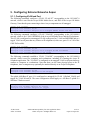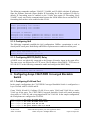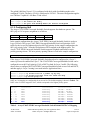
1
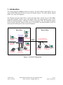
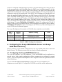
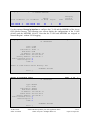
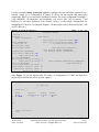
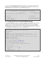
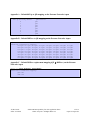
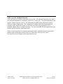
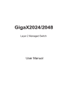
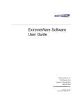
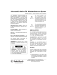
Avaya Solution & Interoperability Test Lab
Application Notes for Extreme Networks Aspen 8810 with
Avaya C364T-PWR Converged Stackable Switch, Avaya
S8500 Media Server and Avaya G650 Media Gateway
- Issue 1.0
Abstract
These Application Notes present a sample quality of service configuration for the Avaya
S8500 Media Server with an Avaya G650 Media Gateway using Extreme Networks Aspen
8810 and Avaya C364T-PWR Converged Stackable Switch. The objective of the test was to
evaluate interoperability of the products in an Enterprise Local Area Network. All test cases
completed successfully. Information in these Application Notes has been obtained through
compliance testing and additional technical discussions. Testing was conducted via the
DeveloperConnection Program at the Avaya Solution and Interoperability Test Lab.
JZ; Reviewed:
SPOC 2/14/2005
Solution & Interoperability Test Lab Application Notes
©2005 Avaya Inc. All Rights Reserved.
1 of 16
Aspen-Ava-QoS.doc
1. Introduction
The network diagram in Figure 1 shows two offices. The office labeled “Main Office” uses an
Avaya S8500 Media Server with an Avaya G650 Media Gateway. The office labeled “Branch
Office” uses Avaya IP telephones.
The Extreme Networks Aspen 8810 is used in the main office, and the Avaya C364T-PWR
Converged Stackable Switch is used in the branch office. The Aspen and the Avaya C364TPWR are connected through a 1000 Base-X (Fiber) or 100 Base-T link. The G48P PoE module
on the Extreme Networks Aspen and the Avaya C364T-PWR Converged Stackable Switch are
used to provide inline power to the Avaya IP telephones.
Main Office
Branch Office
PC
Extreme Networks
Aspen 8810
Avaya 4602SW
IP Telephone
Avaya Digital
Telephone
MEDPRO
IPSI
Avaya S8500
Media Server
C-LAN
DHCP/TFTP
Server
Avaya G650
Media Gateway
1000 Base-X
o r 100 Base-T
Avaya C364T-PWR
Converged Stackable Switch
Avaya IP
Softphone
Avaya 4620SW
IP Telephone
Avaya 4620
IP Telephone
Avaya 4610SW
IP Telephone
PC
Figure 1: Network Configuration
JZ; Reviewed:
SPOC 2/14/2005
Solution & Interoperability Test Lab Application Notes
©2005 Avaya Inc. All Rights Reserved.
2 of 16
Aspen-Ava-QoS.doc
2. Equipment and Software Validated
The following equipment and software were used for the sample configuration provided:
Equipment
Avaya C364T-PWR Converged Stackable Switch
Avaya S8500 Media Server
Avaya Communication Manager
Avaya G650 Media Gateway
IPSI
C-LAN
MEDPRO
Avaya 4602SW IP Telephone
Avaya 4610SW IP Telephone
Avaya 4620 IP Telephone
Avaya 4620SW IP Telephone
Avaya IP Softphone
Avaya 6402D Digital Telephone
Extreme Aspen Switch 8810
G48P (48-port 10/100/1000 Base-T with PoE)
G48T (48-port 10/100/1000 Base-T)
G24X (24-port 1000 Base-X)
Version
4.3.12
2.1.1 (load 414.1)
FW012
FW012
FW095
1.8.3
2.1.3
2.1.3
2.1.3
5.1.4.6
11.1.1.9
Table 1 - Network Component Software Versions
3. Configuration Overview
3.1. Port Configuration Overview
In the main office, ports 3:1 to 3:4 on the Extreme Networks Aspen are used to connect to the
Avaya S8500 Media Server and the Avaya G650 Media Gateway (IPSI, C-LAN and MEDPRO).
It is recommended to configure the Avaya S8500 Media Server and the Avaya G650 Media
Gateway IPSI on one VLAN and the Avaya G650 Media Gateway C-LAN and MEDPRO on
another VLAN. In each of the offices, a set of ports is used to connect end-user devices. For
example, the ports used for end-user devices may connect to a computer, an IP telephone, or an
IP telephone with an attached computer. This is accomplished by configuring two VLANs on the
end-user ports. The tagged VLAN is used for IP telephones, and the untagged VLAN is for
computers, whether standalone, or attached to an IP telephone.
3.2. QoS Configuration Overview
3.2.1. Overview of Avaya QoS Features
The Avaya VoIP components support 802.1p/Q priority and DiffServ. When 802.1Q is enabled
on the Avaya S8500 Media Server and the IPSI board of the Avaya G650 Gateway, VLAN 0
will be used for all outgoing packets. The Extreme Networks Aspen will treat the packets tagged
JZ; Reviewed:
SPOC 2/14/2005
Solution & Interoperability Test Lab Application Notes
©2005 Avaya Inc. All Rights Reserved.
3 of 16
Aspen-Ava-QoS.doc
with VLAN 0 as clear traffic. Therefore, it is recommended to enable DiffServ examination on
these ports.
The Avaya C364T-PWR Converged Stackable Switch supports 802.1p/Q priority for Layer 2
traffic, and can be configured to trust 802.1p/Q priority (CoS) or DSCP or both for Layer 3
traffic.
3.2.2. Overview of Extreme Networks QoS Features
QoS profiles define how the Extreme Networks switch will respond to various categories of
traffic. The parameters defined in the QoS profile include minimum and maximum percentage
bandwidth, priority settings, and other parameters. By default, eight QoS profiles (numbered
QP1-QP8) are assigned priorities that map to eight hardware queues on every physical port. By
default, a higher quality profile number implies a higher transmit priority. For Ethernet
interfaces, traffic can be classified to use a particular QoS profile based on a variety of
parameters, including IP-based information, MAC information, 802.1p, DiffServ, physical
source port, etc. By default, 802.1p is used to classify ingress traffic. Also by default, 802.1p
values 0-6 are classified to QP1 and 802.1p value 7 is classified to QP8. If DiffServ examination
is enabled, DiffServ will override 802.1p for classification of traffic from a port. By default,
DiffServ values 0-55 are classified to QP1. DiffServ values 56-63 are classified to QP8. See
Appendix A and B for default 802.1p and DiffServ to QP mapping.
On egress, the Extreme Networks switch can preserve or replace 802.1p priority values and
DiffServ values. If 802.1p replacement is enabled, the transmitted 802.1p priority is determined
by the hardware queue used to transmit the packet. Thus, on a tagged link, 802.1p replacement
provides a convenient way to request the same priority treatment from the next switch,
independent of the classification method used in the transmitting switch. The switch can also be
configured to re-mark the DiffServ value prior to transmission. The re-marked DiffServ value is
also determined by the hardware queue. DiffServ replacement provides a convenient way to
request the same priority treatment from a next hop that observes DiffServ value, independent of
the classification scheme used by the transmitting switch. See Appendix C for default QP to
DiffServ mapping. The default strict priority queuing is used in these Application Notes.
None of the foregoing QoS operations impact switch performance.
3.2.3. QoS Configuration Employed
In order to simplify QoS configuration, all the ports on the Extreme Networks Aspen are
configured to enable DiffServ Examination. In order to preserve 802.1p/Q priority from the
Extreme Networks Aspen to the Avaya C364T-PWR Converged Stackable Switch, the interoffice link is configured to support tagged VLANs. All the ports are enabled with 802.1p/Q and
DiffServ replacement on the Extreme Networks Aspen.
All the Avaya VoIP components including the Avaya S8500 Media Server, the IP cards in the
Avaya G650 Media Gateway, Avaya IP telephones and Softphones are configured with DiffServ
value 56. In order to support an IP telephone and attached PC in different VLANs, 802.1Q must
be enabled on the IP telephone. The Avaya IP telephones are configured with 802.1p/Q priority
JZ; Reviewed:
SPOC 2/14/2005
Solution & Interoperability Test Lab Application Notes
©2005 Avaya Inc. All Rights Reserved.
4 of 16
Aspen-Ava-QoS.doc
7. Since Extreme Networks switches treat VLAN 0 as clear traffic (untagged VLAN), it does not
matter if 802.1Q is enabled on the Avaya S8500 Media Server and the IPSI of the Avaya G650
Media Gateway.
The Avaya C364T-PWR Converged Stackable Switch trusts 802.1p/Q priority for Layer 2
traffic, and is configured to trust CoS-DSCP for Layer 3 traffic. By configuring to trust CoSDSCP, the Avaya C364T-PWR will use a higher CoS value mapped from 802.p/Q priority and
DSCP. The Avaya C364T-PWR will preserve 802.1p/Q priority from the Avaya IP telephones
to the Extreme Networks Aspen.
Table 2 summarizes the QoS configuration used for the Avaya equipment, and the directly
connected Extreme Networks Aspen. The detailed commands to implement this configuration on
each product are provided in the forthcoming sections.
Avaya
Equipment
IP telephones
PC running IP
Softphone
IPSI on Avaya
G650 Media
Gateway
C-LAN and
MEDPRO on
Avaya G650
Media Gateway
Avaya S8500
Media Server
802.1p/Q and DiffServ
Configuration
IP phone tags with VLAN ID received from
the DHCP server. 802.1p/Q priority and
DiffServ value are received from the IP
network region configured in Avaya
Communication Manager.
(IP telephones are mapped to an IP network
region based on source IP addresses)
DiffServ value is received from the IP
network region configured in Avaya
Communication Manager.
(IP Softphones are mapped to an IP network
region based on source IP addresses).
Using IPSI administration from IPSI
services port to set DiffServ value to 56.
Aspen Port
Configuration
Tagged VLAN on the port
for the IP telephone.
Untagged VLAN for the
PC attached to the phone.
DiffServ value is received from the IP
network region configured in Avaya
Communication Manager.
Untagged VLAN
Use change ip-services interface to set
DiffServ value to 56.
Untagged VLAN
Untagged VLAN to
support any NIC.
Untagged VLAN
Table 2 – QoS and Port Configuration Summary
3.3. DHCP and BOOTP Relay Configuration
Table 3 summarizes the Dynamic Host Configuration Protocol (DHCP) configuration. The
DHCP and TFTP servers are configured on the same PC with IP address 192.168.89.5 (VLAN
89).
In the sample configuration, when an Avaya IP telephone is initially reset, it will send an
untagged DHCP request. The Extreme Networks Aspen and the Avaya Converged Stackable
JZ; Reviewed:
SPOC 2/14/2005
Solution & Interoperability Test Lab Application Notes
©2005 Avaya Inc. All Rights Reserved.
5 of 16
Aspen-Ava-QoS.doc
Switch are configured with both untagged (or native) VLAN 89 and tagged (or static) VLAN 88
for the port connected to the IP telephone. Since the DHCP server is on the untagged VLAN, the
untagged DHCP request will reach the DHCP server directly. The DHCP server associates this
request with the 192.168.89.0 scope and returns a reply with Option 176 string, instructing the IP
telephone to enable 802.1Q tagging with VLAN ID 88. The IP telephone receiving this reply will
release the supplied IP address and issue a new DHCP request with VLAN ID 88. This request
will be associated with the tagged VLAN on the port. The router interface of this VLAN on the
Extreme Networks Aspen has IP address 192.168.88.1 and will relay the DHCP request to the
DHCP server with this address as the source. The DHCP server associates this address with
scope 192.168.88.0 and replies with an IP address from that scope as well as several parameters
in the Option 176 string. MCIPADD=192.168.88.22 in Option 176 configures the C-LAN IP
address of the Avaya G650 Media Gateway. The IP telephone will register to this IP address.
TFTPSRVR=192.168.89.5 in Option 176 configures the TFTP server, and the IP telephone will
use the TFTP server for firmware upgrade.
The Avaya IP telephone will remember its VLAN ID unless explicitly reset to defaults.
DHCP
Scope
Option 3
Router
192.168.88.0
192.168.88.1
192.168.89.0
192.168.89.1
Option 176 String
Notes
MCIPADD=192.168.88.22,
TFTPSRVR=192.168.89.5
L2Q=1,L2QVLAN=88
192.168.88.22C-LAN IP
For untagged
VLAN
Table 3 – DHCP Configuration Summary
4. Configuring the Avaya S8500 Media Server and Avaya
G650 Media Gateway
Refer to reference [1] for detailed configurations of the Avaya S8500 Media Server and G650
Media Gateway. The following sections only show the QoS related configuration.
4.1. Configuring the Avaya S8500 Media Server
The Avaya IP telephones, Avaya IP Softphones, C-LAN and MEDPRO can be configured to a
network region. In the sample configuration, all these components are configured to network
region 1. Avaya IP telephones and Softphones can be assigned to a network region based on their
source IP addresses.
Use the command change ip-network-map to configure the Avaya IP telephones and
Softphones to network region 1. Configure the VLAN ID to match the switch configuration.
JZ; Reviewed:
SPOC 2/14/2005
Solution & Interoperability Test Lab Application Notes
©2005 Avaya Inc. All Rights Reserved.
6 of 16
Aspen-Ava-QoS.doc
change ip-network-map
Page
1 of
32
IP ADDRESS MAPPING
From IP Address
(To IP Address
Subnet
or Mask)
192.168.88 .0
192.168.89 .0
192.168.88 .255
192.168.89 .255
24
24
Region
1
1
VLAN
Emergency
Location
Extension
88
89
Use the command change ip-interface to configure the C-LAN and the MEDPRO of the Avaya
G650 Media Gateway. The following two screens display the configurations of the C-LAN
(01A02) and the MEDPRO (01A03). Note that the C-LAN and MEDPRO are assigned to
Network Region 1 without VLAN tagging.
change ip-interface 01A02
Page
1 of
1
Page
1 of
1
IP INTERFACES
Type:
Slot:
Code/Suffix:
Node Name:
IP Address:
Subnet Mask:
Gateway Address:
Enable Ethernet Port?
Network Region:
VLAN:
C-LAN
01A02
TN799 D
CLAN
192.168.88 .22
255.255.255.0
192.168.88 .1
y
1
n
Number of CLAN Sockets Before Warning: 400
ETHERNET OPTIONS
Auto? y
change ip-interface 01A03
IP INTERFACES
Type:
Slot:
Code/Suffix:
Node Name:
IP Address:
Subnet Mask:
Gateway Address:
Enable Ethernet Port?
Network Region:
VLAN:
MEDPRO
01A03
TN2302
MEDPRO
192.168.88 .21
255.255.255.0
192.168.88 .1
y
1
n
ETHERNET OPTIONS
Auto? y
JZ; Reviewed:
SPOC 2/14/2005
Solution & Interoperability Test Lab Application Notes
©2005 Avaya Inc. All Rights Reserved.
7 of 16
Aspen-Ava-QoS.doc
Use the command change ip-network-region to configure the QoS and other parameters for a
network region. It is recommended to enable IP direct for intra-region and inter-region
connections. RSVP is not used and is disabled by default. The Avaya components including CLAN, MEDPRO, IP telephones, and Softphones will receive QoS (802.1p priority 7 and
DiffServ 56) and other parameters from network region 1 in the sample configuration. By
configuring IP Codec set 1 to Network Region 1, all intra-region calls in Network Region 1 will
use IP Codec set 1.
change ip-network-region 1
Page
1 of
19
IP NETWORK REGION
Region: 1
Location: 1
Name: Location A
Home Domain:
Intra-region IP-IP Direct Audio: yes
Inter-region IP-IP Direct Audio: yes
IP Audio Hairpinning? y
AUDIO PARAMETERS
Codec Set: 1
UDP Port Min: 2048
UDP Port Max: 65534
DIFFSERV/TOS PARAMETERS
Call Control PHB Value: 56
Audio PHB Value: 56
802.1P/Q PARAMETERS
Call Control 802.1p Priority: 7
Audio 802.1p Priority: 7
H.323 IP ENDPOINTS
H.323 Link Bounce Recovery? y
Idle Traffic Interval (sec): 20
Keep-Alive Interval (sec): 5
Keep-Alive Count: 5
RTCP Reporting Enabled? y
RTCP MONITOR SERVER PARAMETERS
Use Default Server Parameters? y
AUDIO RESOURCE RESERVATION PARAMETERS
RSVP Enabled? n
Since Figure 1 is a LAN infrastructure, IP Codec 1 is configured to G.711MU for high voice
quality and is used for the calls in network region 1.
change ip-codec-set 1
Page
1 of
2
IP Codec Set
Codec Set: 1
Audio
Silence
Codec
Suppression
1: G.711MU
n
2:
3:
4:
5:
6:
7:
Media Encryption
1: none
2:
3:
JZ; Reviewed:
SPOC 2/14/2005
Frames
Per Pkt
2
Packet
Size(ms)
20
Solution & Interoperability Test Lab Application Notes
©2005 Avaya Inc. All Rights Reserved.
8 of 16
Aspen-Ava-QoS.doc
Use the command change ipserver-interface to configure the communication to the IPSI. The
following screen shows that DiffServ 56 is configured for the communication from the Avaya
S8500 Media Server to the IPSI of the Avaya G650 Media Gateway.
change ipserver-interface 1
Page
1 of
IP SERVER INTERFACE (IPSI) ADMINISTRATION - PORT NETWORK 1
IP Control? y
Ignore Connectivity in Server Arbitration? n
Primary IPSI
-----------Location: 1A01
Host: 192.168.87.19
DHCP ID: ipsi-A01a
1
Socket Encryption? y
Enable QoS? y
QoS Parameters
-------------Call Control 802.1p: 7
Call Control DiffServ: 56
4.2. Configuring IPSI on the Avaya G650 Media Gateway
To configure the IPSI board, connect the computer (configured with IP address 192.11.13.5 with
netmask 255.255.255.252) to the services port of the IPSI. Telnet to 192.11.13.6 and supply
appropriate login credentials. The following screenshot illustrates the appropriate commands.
The IPSI IP address is configured to 192.168.87.19 with default gateway 192.168.87.1. Note that
VLAN tagging is disabled and DiffServ value is configured to 56.
TN2312 IPSI IP Admin Utility
Copyright Avaya Inc, 2000, 2001, All Rights Reserved
[IPSI]: ipsilogin
Login: craft
Password:
[IPADMIN]: set control interface 192.168.87.19 255.255.255.0
WARNING!! The control network interface will change upon exiting IPADMIN
[IPADMIN]: set control gateway 192.168.87.1
WARNING!! The control network interface will change upon exiting IPADMIN
[IPADMIN]: set vlan tag off
[IPADMIN]: set diffserv 56
[IPADMIN]: show control interface
Control
Control
Control
IPSI is
Network IP Address = 192.168.87.19
Network Subnetmask = 255.255.255.0
Network Default Gateway = 192.168.87.1
not configured for DHCP IP address administration
[IPADMIN]: show qos
QoS values currently in use:
VLAN tagging
:
VLAN id
:
VLAN user priority :
Diffserv value
:
JZ; Reviewed:
SPOC 2/14/2005
off
0
6
56
Solution & Interoperability Test Lab Application Notes
©2005 Avaya Inc. All Rights Reserved.
9 of 16
Aspen-Ava-QoS.doc
5. Configuring Extreme Networks Aspen
5.1.1. Configuring VLAN and Port
The following commands configure a VLAN “VLAN 87” corresponding to the 192.168.87.0
network, which is used for the Avaya S8500 Media Server, and IPSI of the Avaya 650 Media
Gateway. Note that the ports connecting to these Avaya components are all untagged.
create vlan "vlan87"
configure vlan "vlan87" tag 87
configure vlan "vlan87" add port 3:1-2 untagged #S8500 Server and IPSI
The following commands configure a VLAN “VLAN88” corresponding to the 192.168.88.0
network, which is for C-LAN, MEDPRO of the Avaya 650 Media Server and the IP telephones.
This VLAN is configured as an untagged VLAN on the ports for C-LAN and MEDPRO and as a
tagged VLAN on all ports that may connect to IP telephones (in this case, ports 2:1 to 2:48 of the
G48P PoE module).
create vlan "vlan88"
configure vlan "vlan88" tag 88
configure vlan "vlan88" add port 3:3-4 untagged #C-LAN and MEDPRO
configure vlan "vlan88" add port 2:1-48 tagged
The following commands establish a VLAN “VLAN89” corresponding to the 192.168.89.0
network, which is used for computers and workstations, including PCs running the Avaya IP
Softphone application. The “VLAN89” is configured as an untagged VLAN on all ports that may
connect to computers or workstations. Note that these are the same physical ports as the IP
telephones, since a computer may optionally be attached directly to an Avaya IP telephone.
create vlan "vlan89"
configure vlan "vlan89" tag 89
configure vlan "vlan89" add port 2:1-48 untagged
The uplink 1000-Base-X port 4:1 is configured as untagged for VLAN 1 (Default VLAN) and
tagged for VLAN 88 and 89. The same configuration would apply to a 100 Base-T uplink if a
100 Base-T link were used.
config vlan "Default" add port 4:1
onfigure vlan "vlan88" add port 4:1 tagged
configure vlan "vlan89" add port 4:1 tagged
JZ; Reviewed:
SPOC 2/14/2005
Solution & Interoperability Test Lab Application Notes
©2005 Avaya Inc. All Rights Reserved.
10 of 16
Aspen-Ava-QoS.doc
The following commands configure VLAN87, VLAN88, and VLAN89 with their IP addresses.
Since the Extreme Networks Aspen disables IP forwarding for all the configured VLANs by
default, IP forwarding must be enabled on the VLANs that require IP forwarding. Since
VLAN87 is only used for the communication between the S8500 Media Server and the IPSI, IP
forwarding does not have to be enabled on this VLAN.
#Enable IP forwarding
enable ipforwarding vlan "vlan87"
enable ipforwarding vlan "vlan88"
enable ipforwarding vlan "vlan89"
# Configure IP
configure vlan
configure vlan
configure vlan
addresses
"vlan87" ipaddress 192.168.87.1 255.255.255.0
"vlan88" ipaddress 192.168.88.1 255.255.255.0
"vlan89" ipaddress 192.168.89.1 255.255.255.0
5.1.2. Configuring QoS
The following commands establish the QoS configuration. DiffServ examination is used to
classify traffic on all ports. Both Dot1p and DiffServ replacement are enabled on all the ports.
enable diffserv examination ports all
enable dot1p replacement ports all
enable diffserv replacement ports all
5.1.3. Configuring BOOTP (DHCP) Relay
A DHCP server was physically connected to the Extreme Networks Aspen in the main office.
The same server was also used as a TFTP server. The IP address of this DHCP / TFTP server is
192.168.89.5. Use the following command to enable and configure the DHCP Relay.
enable bootprelay
configure bootprelay add 192.168.89.5
6. Configuring Avaya C364T-PWR Converged Stackable
Switch
6.1.1. Configuring VLAN and Port
In the sample configuration, the C364T-PWR Converged Stackable Switch is configured as a
Layer 2 Switch with VLANs 88 and 89.
Create VLANs 88 and 89. Configure VLAN 89 as a native VLAN and VLAN 88 as a staticVLAN on all the ports. The C364T-PWR Converged Stackable Switch will match incoming
clear traffic to VLAN 89, and accept tagged traffic on VLAN 88. In the sample configuration,
the IP telephones are configured on VLAN 88.
C360-1(super)#
C360-1(super)#
C360-1(super)#
C360-1(super)#
JZ; Reviewed:
SPOC 2/14/2005
set
set
set
set
vlan
vlan
port
port
89 name data-vlan
88 name voice-vlan
vlan 89 1/1-48
static-vlan 1/1-48 88
Solution & Interoperability Test Lab Application Notes
©2005 Avaya Inc. All Rights Reserved.
11 of 16
Aspen-Ava-QoS.doc
The uplink 1000 Base-X port 1/51 is configured with dot1q with vlan-binding-mode to the
configured VLANs. The native VLAN is configured to VLAN 1. The same configuration applies
to a 100 Base-T uplink if a 100 Base-T link is used.
C360-1(super)# set port vlan 1 1/51
C360-1(super)# set trunk 1/51 dot1q
C360-1(super)# set port vlan-binding-mode 1/51 bind-to-configured
6.1.2. Configuring QoS
The Avaya C364T-PWR Converged Stackable Switch supports four hardware queues. The
802.1p/Q or CoS to queue assignment is as follows:
CoS
Q1
0,1
Q2
2,3
Q3
4,5
Q4
6,7
In the sample configuration, the Avaya C364T-PWR Converged Stackable Switch is used as a
Layer 2 Switch. The Avaya C364T-PWR Converged Stackable Switch will prioritize VoIP
traffic for the Avaya IP telephones based on 802.1p/Q priority. In the sample configuration, the
802.1p/Q priority value 7 from the IP telephones will be mapped to the highest queue. The
Avaya C364T-PWR Converged Stackable Switch supports weighted round robin or strict
priority queuing scheme. The strict priority queuing scheme is used in the sample configuration.
C360-1(super)# set queuing scheme strict
If the Avaya C364T-PWR Converged Stackable Switch needs to be configured as a Layer 3
router, QoS must be enabled for Layer 3. The C364T-PWR Converged Stackable Switch can be
configured to trust 802.1p/Q priority (CoS) or DSCP or both for Layer 3 traffic. The following
shows show to configure the C364T-PWR Converged Stackable Switch to trust CoS and DSCP,
and then apply it. Layer 3 routing is not used in these Application Notes.
C360-1# session router
Router-1 (super)# ip access-list 101 1 permit ip any any
Router-1 (super)# ip access-list-dscp trust 101 trust-cos-dscp
Router-1(super)# ip access-group 101
DSCP to CoS mapping are configurable for an access list. The default mapping is shown in Table 4. The
DSCP value 56 will be mapped to fwd7, which corresponds to the highest priority queue.
DSCP
------0 – 7
8 – 15
16- 23
24 – 31
32 – 39
40 – 47
48 – 55
56 – 63
Action
----------fwd0
fwd1
fwd2
fwd3
fwd4
fwd5
fwd6
fwd7
Precedence
-----------mandatory
mandatory
mandatory
mandatory
mandatory
mandatory
mandatory
mandatory
Name
--------------DSCP#0 – DSCP#7
DSCP#8 – DSCP#15
DSCP#16 – DSCP#23
DSCP#24 – DSCP#31
DSCP#32 – DSCP#39
DSCP#40 – DSCP#47
DSCP#48 – DSCP#55
DSCP#56 – DSCP#63
Table 4 – Avaya C364T-PWR Converged Stackable Switch Default DSCP-CoS Mapping
JZ; Reviewed:
SPOC 2/14/2005
Solution & Interoperability Test Lab Application Notes
©2005 Avaya Inc. All Rights Reserved.
12 of 16
Aspen-Ava-QoS.doc
7. Interoperability Compliance Testing
This Interoperability Compliance Test included QoS testing between the Extreme Networks
Aspen 8810, the Avaya S8500 Media Server, the Avaya G650 Media Gateway, and the Avaya
4600 Series IP telephones. Basic feature functionality was performed as part of the compliance
testing.
7.1. General Test Approach
Connectivity and QoS test cases were performed manually. During QoS testing, an Ixia data
generator was used to generate low priority traffic. When the 100 Base-T or Gigabit Fiber link
was overloaded, VoIP calls with high quality can still be made between the main and branch
offices.
7.2. Test Results
All the related test cases passed successfully. No errors were detected. QoS features based on
802.1p/Q priority and DiffServ on the Extreme Networks Aspen 8810 worked well with the
Avaya C364T-PWR Converged Stackable Switch, Avaya S8500 Media Server, Avaya G650
Media Gateway, and Avaya IP telephones.
8. Verification Steps
The following are verification steps for these Applications Notes:
•
•
•
•
Verify that the IP telephones and Softphones register with the C-LAN of the Avaya G650
Media Gateway. Use mute “767#” (“QoS”#) on the Avaya IP telephones to verify the
QoS configuration.
Verify that an IP telephone and the PC attached to the telephone are on different VLANs.
Verify that the calls use G.711 Codec (use the command status station <extension> to
verify which Codec is used on the Avaya S8500 Media Server for an active call).
While generating data traffic between the main office and the branch office to overload
the 100 Base-T or Gigabit Fiber link, make a call between the main office and the branch
office. Verify that voice quality is acceptable.
9. Support
Customers should call Extreme Networks Worldwide TAC when having problems related to
Extreme Networks switches. Technical support is also available at the Extreme Networks web
site at http://www.extremenetworks.com/services/wwtac/.
Product documentation for Extreme Networks can be downloaded via web at
http://www.extremenetworks.com/services/documentation/.
JZ; Reviewed:
SPOC 2/14/2005
Solution & Interoperability Test Lab Application Notes
©2005 Avaya Inc. All Rights Reserved.
13 of 16
Aspen-Ava-QoS.doc
10. Conclusion
Extreme Networks Aspen 8810 Switch was compliance-tested with the Avaya S8500 Media
Server, Avaya G650 Media Gateway, Avaya C364T-PWR Converged Stackable Switch and
Avaya IP telephones. All feature functionality and QoS test cases completed successfully.
11. Additional References
Application Notes:
[1]
JZ; Reviewed:
SPOC 2/14/2005
Application Notes for Extreme Networks Switches Using Gigabit Ethernet
Modules with Avaya S8700 Media Servers and Avaya G600 Media Gateways
Controlling Avaya G700 Media Gateways
Solution & Interoperability Test Lab Application Notes
©2005 Avaya Inc. All Rights Reserved.
14 of 16
Aspen-Ava-QoS.doc
Appendix A – Default 802.1p to QP mapping on the Extreme Networks Aspen
Aspen.3 # show dot1p
802.1p Priority Value
0
1
2
3
4
5
6
7
QOS Profile
QP1
QP1
QP1
QP1
QP1
QP1
QP1
QP8
Appendix B – Default DiffServ to QP mapping on the Extreme Networks Aspen
Aspen.4 # show diffserv examination
CodePoint->QOSProfile mapping:
00->QP1 01->QP1 02->QP1 03->QP1
08->QP1 09->QP1 10->QP1 11->QP1
16->QP1 17->QP1 18->QP1 19->QP1
24->QP1 25->QP1 26->QP1 27->QP1
32->QP1 33->QP1 34->QP1 35->QP1
40->QP1 41->QP1 42->QP1 43->QP1
48->QP1 49->QP1 50->QP1 51->QP1
56->QP8 57->QP8 58->QP8 59->QP8
04->QP1
12->QP1
20->QP1
28->QP1
36->QP1
44->QP1
52->QP1
60->QP8
05->QP1
13->QP1
21->QP1
29->QP1
37->QP1
45->QP1
53->QP1
61->QP8
06->QP1
14->QP1
22->QP1
30->QP1
38->QP1
46->QP1
54->QP1
62->QP8
07->QP1
15->QP1
23->QP1
31->QP1
39->QP1
47->QP1
55->QP1
63->QP8
Appendix C – Default DiffServ replacement mapping (QP Æ DiffServ) on the Extreme
Networks Aspen
Aspen.5 # show diffserv replacement
QOSProfile->CodePoint mapping:
QP1->00
QP8->56
JZ; Reviewed:
SPOC 2/14/2005
Solution & Interoperability Test Lab Application Notes
©2005 Avaya Inc. All Rights Reserved.
15 of 16
Aspen-Ava-QoS.doc
©2005 Avaya Inc. All Rights Reserved.
Avaya and the Avaya Logo are trademarks of Avaya Inc. All trademarks identified by ® and ™
are registered trademarks or trademarks, respectively, of Avaya Inc. All other trademarks are the
property of their respective owners. The information provided in these Application Notes is
subject to change without notice. The configurations, technical data, and recommendations
provided in these Application Notes are believed to be accurate and dependable, but are
presented without express or implied warranty. Users are responsible for their application of any
products specified in these Application Notes.
Please e-mail any questions or comments pertaining to these Application Notes along with the
full title name and filename, located in the lower right corner, directly to the Avaya
DeveloperConnection Program at [email protected].
JZ; Reviewed:
SPOC 2/14/2005
Solution & Interoperability Test Lab Application Notes
©2005 Avaya Inc. All Rights Reserved.
16 of 16
Aspen-Ava-QoS.doc