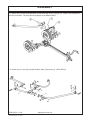
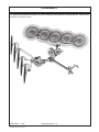
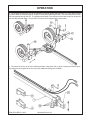
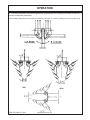
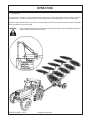
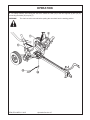
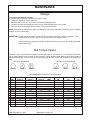
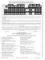
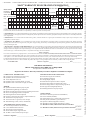
1
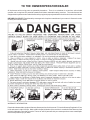
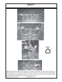
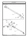
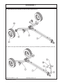
ER8/ER10/ER12
R
Econo V-Rake
Published 03/07
4929WC
OPERATOR'S MANUAL
This Operator's Manual is an integral part of the safe operation
of this machine and must be maintained with the unit at all
times. READ, UNDERSTAND, and FOLLOW the Safety and
Operation Instructions contained in this manual before
operating the equipment.
M&W®
1020 South Sangamon Ave.
Gibson City, Illinois 60936
217-784-4261
© 2007lamo Group Inc.
$0.00
TO THE OWNER/OPERATOR/DEALER
All implements with moving parts are potentially hazardous. There is no substitute for a cautious, safe-minded
operator who recognizes the potential hazards and follows reasonable safety practices. The manufacturer has
designed this implement to be used with all its safety equipment properly attached to minimize the chance of accidents.
BEFORE YOU START!! Read the safety messages on the implement and shown in your manual. Observe the rules
of safety and common sense!
WARRANTY INFORMATION:
Read and understand the complete Warranty Statement found in this manual. Fill out the Warranty Registration Form
in full and return it within 30 Days. Make certain the Serial Number of the machine is recorded on the Warranty Card
and on the Warranty Form that you retain. The use of "will-fit" parts will void your warranty and can cause catastrophic
failure with possible injury or death.
TABLE OF CONTENTS
SAFETY SECTION ......................................................................................................................................... 1-1
Decal Location ................................................................................................................................................ 1-4
Federal Laws & Regulations ................................................................................................................... 1-7
INTRODUCTION SECTION ............................................................................................................................. 2-1
Attention Owner/Operator ................................................................................................................................ 2-2
ASSEMBLY SECTION ................................................................................................................................... 3-1
OPERATION SECTION .................................................................................................................................. 4-1
Adjustments for Machine Use .......................................................................................................................... 4-2
Swatch Measurements .................................................................................................................................... 4-5
Transporting .................................................................................................................................................... 4-6
Troubleshooting .............................................................................................................................................. 4-8
MAINTENANCE SECTION ............................................................................................................................. 5-1
Storage ........................................................................................................................................................... 5-3
Bolt Torque Values .......................................................................................................................................... 5-3
PARTS SECTION ........................................................................................................................................... 6-1
Important
This service manual is presented to you for assistance in the operation and maintenance of your M&W Equipment.
There will be a charge for manuals requested after the original issue on purchased or leased equipment.Contact
your M&W dealer for replacement parts. Requests for additional manuals should be directed to:
M&W
1020 South Sangamon Avenue
Gibson City, IL 60936
When ordering parts for this manual be sure that orders for replacement parts include the following information:
1. Name of machine
2. Machine model number
3. Machine seial number (The serial number plate is located on the front of the 3-point frame)
4. Quantity of part required
5. M&W part number (from manual)
6. Description of part
M&W, whose policy it is to continuously improve its products, reserve the right to discontinue or change
specification, models or design without notice and without incurring obligation.
Record the following information for future reference:
Model No.:_________________________________
Serial No.:_________________________________
Date of Purchase:___________________________
SAFETY
SECTION
Safety Section 1-1
SAFETY
A safe and careful operator is the best operator. Safety is of primary importance to the
manufacturer and should be to the owner/operator. Most accidents can be avoided by being
aware of your equipment, your surroundings, and observing certain precautions. The first section
of this manual includes a list of Safety Messages that, if followed, will help protect the operator
and bystanders from injury or death. Read and understand these Safety Messages before
assembling, operating or servicing this mower. This equipment should only be operated by
those persons who have read the Manual, who are responsible and trained, and who know how
to do so safely and responsibly.
The Safety Alert Symbol combined with a Signal Word, as seen below, is used throughout this
manual and on decals which are attached to the equipment. The Safety Alert Symbol means:
“ATTENTION! BECOME ALERT! YOUR SAFETY IS INVOLVED!” The Symbol and Signal
Word are intended to warn the owner/operator of impending hazards and the degree of possible
injury faced when operating this equipment.
Practice all usual and customary safe working precautions and
above all---remember safety is up to YOU. Only YOU can prevent
serious injury or death from unsafe practices.
CAUTION!
The lowest level of Safety Message; warns of possible injury. Decals
located on the Equipment with this Signal Word are Black and Yellow.
WARNING!
Serious injury or possible death! Decals are Black and Orange.
DANGER!
Imminent death/critical injury. Decals are Red and White. (SG-1)
ER8 ,ER10 &ER12 03/07
© 2007 Alamo Group Inc.
Safety Section 1-2
SAFETY
READ, UNDERSTAND, and FOLLOW the following Safety
Messages. Serious injury or death may occur unless care is
taken to follow the warnings and instructions stated in the Safety
Messages. Always use good common sense to avoid hazards.
(SG-2)
PELIGRO!
Si no lee Ingles, pida ayuda a alguien que si lo lea
para que le traduzca las medidas de seguridad. (SG-3)
DANGER!
Never operate the Tractor or Implement until you have read and
completely understand this Manual, the Tractor Operator’s Manual,
and each of the Safety Messages found in the Manual or on the Tractor
and Implement. Learn how to stop the tractor engine suddenly in an
emergency. Never allow inexperienced or untrained personnel too
operate the Tractor and Implement without supervision. Make sure
the operator has fully read and understood the manuals prior to
operation. (SG-4)
WARNING!
Always maintain the safety decals in good readable condition. If the decals are missing, damaged,
or unreadable, obtain and install replacement decals immediately. (SG-5)
WARNING!
Make certain that the “Slow Moving Vehicle” (SMV) sign is installed in
such a way as to be clearly visible and legible. When transporting the
Equipment use the Tractor flashing warning lights and follow all local traffic
regulations. (SG-6)
WARNING!
Operate this Equipment only with a Tractor equipped with an approved
roll-over-protective system (ROPS). Always wear seat belts. Serious
injury or even death could result from falling off the tractor--particularly
during a turnover when the operator could be pinned under the ROPS.
¡LEA EL
INSTRUCTIVO!
(SG-7)
WARNING!
Do not modify or alter this Implement. Do not permit anyone to modify or alter this Implement,
any of its components or any Implement function. (SG-8)
DANGER!
BEFORE leaving the tractor seat, always engage the brake and/or set the
tractor transmission in parking gear, disengage the PTO, stop the engine,
remove the key, and wait for all moving parts to stop. Place the tractor shift
lever into a low range or parking gear to prevent the tractor from rolling.
Never dismount a Tractor that is moving or while the engine is running.
Operate the Tractor controls from the tractor seat only. (SG-9)
DANGER!
Never allow children or other persons to ride on the Tractor or Implement.
Falling off can result in serious injury or death.
(SG-10)
ER8 ,ER10 &ER12 03/07
© 2007 Alamo Group Inc.
Safety Section 1-3
SAFETY
DANGER!
Never allow children to operate or ride on the Tractor or Implement.
(SGM-11)
WARNING!
Do not mount the Tractor while the tractor is moving. Mount the
Tractor only when the Tractor and all moving parts are completely
(SG-12)
stopped.
DANGER!
Start tractor only when properly seated in the Tractor seat. Starting a
tractor in gear can result in injury or death. Read the Tractor operators
manual for proper starting instructions. (SG-13)
DANGER!
Never work under the Implement, the framework, or any lifted component unless the Implement is securely supported or blocked up to
prevent sudden or inadvertent falling which could cause serious injury
or even death. (SG-14)
WARNING!
The operator and all support personnel should wear hard hats, safety
shoes, safety glasses, and proper hearing protection at all times for
protection from injury including injury from items thrown by the
equipment.
(SG-16)
DANGER!
Do not operate this Equipment with hydraulic oil leaking. Oil is
expensive and its presence could present a hazard. Do not check for
leaks with your hand! Use a piece of heavy paper or cardboard. Highpressure oil streams from breaks in the line could penetrate the skin
and cause tissue damage including gangrene. If oil does penetrate
the skin, have the injury treated immediately by a physician
knowledgeable and skilled in this procedure. (SG-15)
ER8 ,ER10 &ER12 03/07
© 2007 Alamo Group Inc.
Safety Section 1-4
SAFETY
CAUTION!
PROLONGED EXPOSURE TO LOUD NOISE MAY CAUSE
PERMANENT HEARING LOSS! Tractors with or without an
Implement attached can often be noisy enough to cause permanent
hearing loss. We recommend that you always wear hearing
protection if the noise in the Operator’s position exceeds 80db.
Noise over 85db over an extended period of time will cause severe
hearing loss. Noise over 90db adjacent to the Operator over an
extended period of time will cause permanent or total hearing loss.
Note: Hearing loss from loud noise [from tractors, chain saws,
radios, and other such sources close to the ear] is cumulative over a
lifetime without hope of natural recovery. (SG-I7)
WARNING!
Transport only at safe speeds. Serious accidents and injuries can
result from operating this equipment at unsafe speeds. Understand the
Tractor and Implement and how it handles before transporting on streets
and highways. Make sure the Tractor steering and brakes are in good
condition and operate properly.
Before transporting the Tractor and Implement, determine the safe
transport speeds for you and the equipment. Make sure you abide
by the following rules:
1.
2.
3.
Test the tractor at a slow speed and increase the speed slowly.
Apply the Brakes smoothly to determine the stopping characteristics
of the Tractor and Implement. As you increase the speed of the
Tractor the stopping distance increases. Determine the maximum
safe transport speed for you and this Equipment.
Test the equipment at a slow speed in turns. Increase the speed
through the turn only after you determine that it is safe to operate
at a higher speed. Use extreme care and reduce your speed when
turning sharply to prevent the tractor and implement from turning
over. Determine the maximum safe turning speed for you and this
equipment before operating on roads or uneven ground.
Only transport the Tractor and Implement at the speeds that you
have determined are safe and which allow you to properly control
the equipment.
Be aware of the operating conditions. Do not operate the Tractor with
weak or faulty brakes. When operating down a hill or on wet or rain
slick roads, the braking distance increases: use extreme care and reduce
your speed. When operating in traffic always use the Tractor’s flashing
warning lights and reduce your speed. Be aware of traffic around you
and watch out for the other guy. (SG-19)
WARNING!
WARNING!
Never attempt to lubricate, adjust, or remove material from the Implement while it is in motion
or while tractor engine is running. Make sure the tractor engine is off before working on the
Implement.
(SG-20)
Always read carefully and comply fully with the manufacturers instructions
when handling oil, solvents, cleansers, and any other chemical agent.
(SG-22)
ER8 ,ER10 &ER12 03/07
© 2007 Alamo Group Inc.
Safety Section 1-5
SAFETY
WARNING!
Periodically inspect all moving parts for wear and replace when
necessary with authorized service parts. Look for loose fasteners,
worn or broken parts, and leaky or loose fittings. Make sure all pins
have cotter pins and washers. Serious injury may occur from not
maintaining this machine in good working order. (SG-21)
DANGER!
Never run the tractor engine or mower engine in a closed building or without adequate
(SG-23)
ventilation. The exhaust fumes can be hazardous to your health.
DANGER!
KEEP AWAY FROM ROTATING ELEMENTS to prevent entanglement
and possible serious injury or death.
(SG-24)
DANGER!
Never allow children to play on or around Tractor or Implement. Children can slip or fall off the
Equipment and be injured or killed. Children can cause the Implement to shift or fall crushing
themselves or others. (SG-25)
DANGER!
NEVER use drugs or alcohol immediately before or while operating the
Tractor and Implement. Drugs and alcohol will affect an operator’s
alertness and coordination and therefore affect the operator’s ability to
operate the equipment safely. Before operating the Tractor or
Implement, an operator on prescription or over-the-counter medication must consult a medical professional regarding any side effects
of the medication that would hinder their ability to operate the
Equipment safely. NEVER knowingly allow anyone to operate this
equipment when their alertness or coordination is impaired. Serious
injury or death to the operator or others could result if the operator is
under the influnce of drugs or alcohol. (SG-27)
DANGER!
Operate the Tractor and/or Implement controls only while properly seated in the Tractor seat with
the seat belt securely fastened around you. Inadvertent movement of the Tractor or Implement may
cause serious injury or death. (SG-29)
DANGER!
Be particularly careful when transporting the Implement using the tractor. Turn curves or go up or
down hills only at a low speed and at a gradual steering angle. Make certain that at least 20% of
the tractor’s weight is on the front wheels to maintain safe steerage. Slow down on rough or uneven
surfaces. (STI-1)
ER8 ,ER10 &ER12 03/07
© 2007 Alamo Group Inc.
Safety Section 1-6
SAFETY
WARNING!
Never leave Tractor and Implemented unattended while the implement is in the lifted position.
Accidental operation of lifting lever or a hydraulic failure
may cause sudden drop of unit with
injury or death by crushing. To properly park the implement when disconnecting it from the tractor,
lower the stand and put the retaining pin securely in place, or put a secure support under the AFrame. Lower the implement carefully to the ground. Do not put hands or feet under lifted
components. (S3PT-1)
WARNING!
Be particularly careful when transporting the Implement with the Tractor. Turn curves or go up hills
only at a low speed and using a gradual steering angle. Rear mounted implements move the
center of gravity to the rear and remove weight from the front wheels. Make certain, by adding
front ballast, that at least 20% of the tractor’s weight is on the front wheels to prevent rearing up,
loss of steering control or Tractor tip-over. Slow down on rough or uneven surfaces to prevent
loss of steering control which could result in property damage or possible injury. Do not transport
unless 3-Point lift lever is fully raised and in the latched transport position. Dropping implement in
transport can cause serious damage to the tractor and/or Implement and possibly cause the
operator or others to be injured or killed. (S3PT-2)
DANGER!
A rear Implement can fall if not properly supported. Always use the stand on the front hitch (if
equipped) or block up securely to prevent falling and possible crushing injury and/or other injury from
holding or lifting heavy components. Use the stand to stabilize the implement during storage.
(S3PT-3)
CAUTION!
Do not back up with this implement. Backing could damage the machine or its components
(S3PT-4)
WARNING!
Use extreme care when lowering or unfolding the implement’s wings. Make sure no bystanders
are close by or underneath the wings. Allow ample clearance around the implement when folding
or unfolding the wings. Use extreme caution around buildings or overhead power lines. (S3PT-5)
WARNING!
Relieve hydraulic pressure prior to doing any maintenance or repair
work on the Implement. Place the Implement on the ground or
securely blocked up, disengage the PTO, and turn off the tractor
engine. Push and pull the Remote Cylinder lever in and out several
times prior to starting any maintenance or repair work. (S3PT-9)
DANGER!
This Implement is wider than the Tractor. Be careful when operating or transporting this
equipment to prevent the Implement from running into or striking sign posts, guard rails,
concrete abutments or other solid objects. Such an impact could cause the Implement and
Tractor to pivot violently resulting in loss of steering control, serious injury, or even death.
Never allow the Implement to contact obstacles. (S3PT-12)
DANGER!
When the Wings are folded for transport, the center of gravity is raised and the possibility of
overturn is increased. Drive slowly and use extremecaution when turning on hillsides. Overturning
the Implement could cause the Implement to overturn the Tractor and vice versa resulting in serious
injury or even death. Never fold wings on a hillside...the Implement may overturn. (STI-2)
ER8 ,ER10 &ER12 03/07
© 2007 Alamo Group Inc.
Safety Section 1-7
SAFETY
DANGER!
DO NOT allow any person under a folded wing unless wing is securely
locked up or supported. DO NOT approach the Implement unless the
Tractor is turned off and all motion has ceased. Never work under the
frame work, or any lifted component unless the implement is securely
supported or blocked up. A sudden or inadvertent fall by any of these
components could cause serious injury or even death. (STI-3)
WARNING!
Never unhitch without using the Tongue Jack. The Tongue is very heavy. Attempting to
lift the Tongue without using the Tongue Jack could cause strains or other injury. Allowing
the tongue to fall suddenly and unexpectedly could result in crushing injury. Use the
Tongue Jack for lifting the mower only. Overloading the Tongue Jack can cause failure
with possible serious bodily injury or even death. (STI-4)
CAUTION!
On a fully-assembled unit, do not remove the Wing Retaining Strap until hoses are attached
to the tractor and the Wing Cylinders are filled with oil. Lower the Wings slowly and
carefully. Keep bystanders away during operations. (STI-5)
DANGER!
Do not operate the implement while wearing loose fitting clothing. Entanglement of the clothing with
the rotating elements can result in serious injury or even death. Stay clear of all rotating elements
at all times. (SSP-3)
DANGER!
There are obvious and hidden potential hazards in the operation of this Rake as in all powerdriven or pulled equipment. REMEMBER! This machine is often operated in rough conditions and
terrain that could include tall grass, weeds, gullies, holes, slopes, hidden obstructions and the like.
Serious injury or even death may occur unless care is taken to assure the safety of the operator and
bystanders in the area. Do not operate this machine with anyone in the immediate area. Stop
raking if anyone comes within 25 feet of the equipment. (SSP-5)
WARNING!
Only tow the Implement behind a properly sized and equipped Tractor which exceeds the weight
of the Implement by at least 20%. DO NOT tow the Implement behind a truck or other type of
vehicle. Never tow the Implement and another Implement connected in tandem. Never tow the
Implement at speeds over 20 MPH. (STI-6)
In addition to the design and configuration of this Implement, including Safety Signs and Safety Equipment, hazard
control and accident prevention are dependent upon the awareness, concern, prudence, and proper training of
personnel involved in the operation, transport, maintenance, and storage of the machine. Refer also to Safety
Messages and operation instruction in each of the appropriate sections of the Tractor and Equipment Manuals.
Pay close attention to the Safety Signs affixed to the Tractor and Equipment. (SG-18)
PARTS INFORMATION
M&W implement use matched system components for blades, hangers, rollers, and bearings. These parts
are made and tested to M&W specifications. Non-genuine "will fit" parts do not consistently meet these
specifications. The use of “will fit” parts may reduce implements performance, void warranties, and present
a safety hazard. Use genuine M&W mower parts for economy and safety. (SPMW-1)
SEE YOUR M&W DEALER
ER8 ,ER10 &ER12 03/07
© 2007 Alamo Group Inc.
Safety Section 1-8
NOTES
SAFETY
SMV
7
NOTE: M&W supplies safety decals on this product to promote safe operation. Damage to the decals may occur
while in shipping, use, or reconditioning. M&W cares about the safety of its customers, operators, and bystanders,
and will replace the safety decals on this product in the field, free of charge (Some shipping and handling charges
may apply). Contact your M&W dealer to order replacement decals.
ER8 ,ER10 &ER12 03/07
© 2007 Alamo Group Inc.
Safety Section 1-10
SAFETY
ITEM
PART NO.
QTY.
DESCRIPTION
1
2
3
4
6
7
9
10
11
12
13
14
16
17
18
999001
00771039
00763977
1438311
5W119
1828300
02962764
00756059
3668308
02962765
2738333
NA
999200
00725746
3668309
3668310
3668319
2738332
1
1
1
2
1
*
4
3
2
2
4
1
1
1
2
2
2
2
Decal, Caution
Decal, Use Genuine M&W Parts
Decal, Notice to Owner
Decal, M&W
Decal, Warning - Speed
SMV Reflector
Decal, Pinch Point
Decal, Warning - Oil Leak
Decal, Warning Transport
Decal, Multiple Hazard
Decal, Yellow Oblong Reflector
Serial Number Plate
Decal, Warning
Decal, Peligro
Decal, Model ER8
Decal, Model ER10
Decal, Model ER12
Decal, Red Oblong Reflector
19
02962764
* Provided by Tractor Manufacturer
999200
3668308
00771039
ER8 ,ER10 &ER12 03/07
© 2007 Alamo Group Inc.
Safety Section 1-11
SAFETY
2738332
00725746
2738333
00756059
02962765
1828300
1438311
00763977
MODEL ER8
3668309
MODEL ER10
3668310
MODEL ER12
999001
3668319
5W119
ER8 ,ER10 &ER12 03/07
© 2007 Alamo Group Inc.
Safety Section 1-12
SAFETY
FEDERAL LAWS AND REGULATIONS
This section is intended to explain in broad terms the concept and effect of federal laws and regulations concerning
employer and employee equipment operators. This section is not intended as a legal interpretation of the law and
should not be considered as such.
Employer-Employee Operator Regulations
U.S. Public Law 91-596 (The Williams-Steiger Occupational and Health Act of 1970) OSHA
This Act Seeks:
“...to assure so far as possible every working man and woman in the nation safe and healthful working conditions
and to preserve our human resources...”
DUTIES
Sec. 5 (a) Each employer(1) shall furnish to each of his employees employment and a place of employment which are free from recognized
hazards that are causing or are likely to cause death or serious physical harm to his employees;
(2) shall comply with occupational safety and health standards promulgated under this Act.
(b) Each employee shall comply with occupational safety and health standards and all rules, regulations and
orders issued pursuant to this Act which are applicable to his own actions and conduct.
OSHA Regulations
OSHA regulations state in part: “At the time of initial assignment and at least annually thereafter, the employer
shall instruct every employee in the safe operation and servicing of all equipment with which the employee is, or will
be involved.”
Employer Responsibilities:
To ensure employee safety during Tractor and Implement operation, it is the employer’s responsibility to:
1. Train the employee in the proper and safe operation of the Tractor and Implement.
2. Require that the employee read and fully understand the Tractor and Implement Operator’s manual.
3. Permit only qualified and properly trained employees to operate the Tractor and Implement.
4. Maintain the Tractor and Implement in a safe operational condition and maintain all shields and guards on the
equipment.
5. Ensure the Tractor is equipped with a functional ROPS and seat belt and require that the employee operator
securely fasten the safety belt and operate with the ROPS in the raised position at all times.
6. Forbid the employee operator to carry additional riders on the Tractor or Implement.
7. Provide the required tools to maintain the Tractor and Implement in a good safe working condition and provide
the necessary support devices to secure the equipment safely while performing repairs and service.
8. Require that the employee operator stop mowing if bystanders or passerbys come within 100 yards.
Child Labor Under 16 Years of Age
Some regulations specify that no one under the age of 16 may operate power machinery. It is your responsibility
to know what these regulations are in your own area or situation. (Refer to U.S. Dept. of Labor, Employment
Standard Administration, Wage & Home Division, Child Labor Bulletin #102.)
ER8 ,ER10 &ER12 03/07
© 2007 Alamo Group Inc.
Safety Section 1-13
INTRODUCTION
SECTION
Introduction Section 2-1
INTRODUCTION
This Rake is designed with care and built with quality materials by skilled workers. Proper assembly,
maintenance, and operating practices, as described in this manual, will help the owner/operator get years
of satisfactory service from the machine.
The purpose of this manual is to familiarize, instruct, and train. The Safety Section is a MUST READ section
prior to any use of the rake. The Assembly Section instructs the owner/operator in the correct assembly of
the Rake using standard and optional equipment. Careful use and timely service saves extensive repairs
and costly downtime losses. The Operation Section informs the owner/operator how to work the rake and
explains proper procedures and safe practices prior to and during the operation of the rake. The TroubleShooting Guide helps diagnose difficulties with the rake and offers solutions to the problems. The
Maintenance Section instructs the owner/operator of all the necessary inspection, lubrication, general
maintenance needed to insure long life and trouble free operation of your rake. The Parts Listing section is
designed to familiarize the owner/operator with replaceable parts on the Rake.
Safety is of primary importance to the owner/operator and to the manufacturer. The first section of this
manual includes a list of Safety Messages, that, if followed, will help protect the operator and bystanders from
injury or death. Many of the Safety Messages will be repeated throughout the manual. The owner/operator/
dealer should know these Safety Messages before assembly and be aware of the hazards of operating this
rake during assembly, use, and maintenance. The Safety Alert Symbol combined with a Signal Word, as
seen below, is intended to warn the owner/operator of impending hazards and the degree of possible injury
faced when operating this machine.
CAUTION!
The lowest level of Safety Message; warns of possible minor injury. Decals located on the
Mower with this Signal Word are Black and Yellow.
WARNING!
Serious injury or possible death! Decals are Black and Orange.
DANGER!
Imminent death/critical injury. Red and White Decals.
ATTENTION OWNER/OPERATOR
BEFORE OPERATING THIS MACHINE:
1. Carefully read the Operator’s Manual, completely understand the Safety Messages and instructions, and
know how to operate correctly, both the tractor and Rake.
2. Fill out the Warranty Card in full, and mail promptly. Be sure to answer all questions, including the Serial
Number of the Rake.
NOTE: Warranties are honored only if completed “Owner Registration and Warranty” cards are received by
Alamo Group within thirty days of delivery of the Rake.
3. Record the Rake Model and Serial Number on the Warranty card at the front of the Operator’s Manual.
Keep this as part of the permanent maintenance file for the Rake.
ER8,ER10 & ER12 11/04
© 2007 Alamo Group Inc.
Introduction Section 2-2
ASSEMBLY
SECTION
Assembly Section 3-1
ASSEMBLY
Assembly must be done carefully and accurately, for the safety of the person(s) doing the assembling and to
ensure proper machine operation. Assembly should be done on a flat, solid surface, using the proper tools and
wearing suitable clothing, making sure that all people not involved in the assembly be kept at a safe distance.
Assemblers must provide suitable lifting mechanisms and supports for stabilizing the partially assembled units,
so at to prevent them from falling and causing damage or injury. The steps for assembly are illustrated in
following. Depending on the experience of the assemblers and the tools available, it is not necessary that the
instructions be followed in the exact order given here, but the safety precautions described above must always
be followed carefully and scrupulously.
IMPORTANT: THESE SIGNS AND SYMBOLS GIVE INFORMATION TO THE OPERATOR ON HOW TO
MAKE THE BEST USE OF THE MACHINE SO AS TO PROLONG LIFE, AVOID DAMAGE, OPTIMIZE WORK
AND, ABOVE ALL, TO AVOID INJURY TO THE OPERATOR AND ANYONE WITHIN RANGE OF THE
MACHINE.
1. Before beginning operations, read the instruction manual carefully.
2. Before doing any maintenance or repair work, stop the machine at a suitable spot. Turn off the tractor
engine, apply the brake, remove the key from the ignition and consult this manual.
3. This is a warning to use proper accident protection when carrying out maintenance and repairs.
4. Indicates an impending dangerous situation which, if not avoided, will cause death or severe personal injury.
5. Indicates a potentially dangerous situation which, if not avoided, could cause death or severe personal injury,
including dangers which are present when protection is removed.
6. Indicates a potentially dangerous situation which, if not avoided, can provoke less severe or minor injuries.
ER8 ,ER10 &ER12 11/04
© 2004 Alamo Group Inc.
Assembly Section 3-2
ASSEMBLY
1. Attach the tractor hitch (35) to the drawbar (1) using the two pins (37), fastening with the12mm x 20mm bolts
(40) and washers (26).
2. Attach the drawbar (1) to the frame (2) centering it between plates (A) and fastening it with the plate (7),
16mm x 150mm bolts (27), and nuts (29).
ER8 & ER10 11/04
© 2004 Alamo Group Inc.
Assembly Section 3-3
ASSEMBLY
3. Mount wheels (53) to hubs (B) on frame (2) using 16mm nuts (47).
4. Attach mount (D) of the drawbar parking stand (11) to pin (C) on drawbar (1) and fasten with pins (14) & (39).
ER8 ,ER10 &ER12 11/04
© 2004 Alamo Group Inc.
Assembly Section 3-4
ASSEMBLY
5. Insert pins (12) into holes (E) on the cart and holes (F) on the arms (3) & (4), so that arms (3) & (4) are hinged
to the cart. Fasten pins (12) with pins (33).
6. Attach the cylinders (25) to the lugs (G) and (H) using pins (13) and pins (32).
ER8 & ER10 11/04
© 2004 Alamo Group Inc.
Assembly Section 3-5
ASSEMBLY
7. Hydraulic System Assembly
A) Attach washers (18) and the restrictor fitting (19) at ports V on cylinders (25). If the restrictor fitting (19) is an "A"
type, attach the side with the restrictor hole towards port V on cylinders (25). If fitting (19) is a "B" type, either side can
be connected.
B) Attach 90o hose end (16) to the reducer fittings (19) and join them at the center with Tee fitting (22).
C) Attach washer (18) and adapter fitting (20) at holes X on cylinder (25).
D) Attach washer (18), swivel adapter (21), and adapter (22), to hole (Z) on the other cylinder.
E) Connect 90o hose end (17) to fitting (20), and the straight end to adapter (22).
F) Connect the swivel ends of hoses (15) to adapter (22).
G) Place washers (23) and connect the quick release coupling (24) to the straight male ends of hoses (15).
H) Check to make sure that all connections are correctly fastened.
I) Attach the hose collar (54) to the lugs on drawbar, fastening on, correctly position (see step 9).
ER8 ,ER10 &ER12 11/04
© 2004 Alamo Group Inc.
Assembly Section 3-6
ASSEMBLY
8A. Fasten supports (8) and (10) to the frame using plates (34), 16x150mm (27), and nuts (29).
8B. Supports (8) and (10) can also be attached by passing the bolts through slot (M). This position is particularly useful for model ER8.
ER8 & ER10 11/04
© 2004 Alamo Group Inc.
Assembly Section 3-7
ASSEMBLY
9. The cart is now completely assembled and we can begin the assembly of the hay rakes.
10. Place the pivoting bracket (2) over support (8), fastening it with the bushing (9) and 12mm roll pin (29).
ER8 ,ER10 &ER12 11/04
© 2004 Alamo Group Inc.
Assembly Section 3-8
ASSEMBLY
11. Attach arm (3) to the pivoting bracket (2) and fasten with lever (7) and pin (4). Shown in the illustration is
the ER10 Hay Rake. The same procedure applies to the ER8 and ER12.
12. Attach arm (1) to arm (25) using M14x40mm bolts (12) and nuts (3). (ER10 &ER12)
12
1
3
25
ER8 & ER10 11/04
© 2004 Alamo Group Inc.
Assembly Section 3-9
ASSEMBLY
13. Attach brackets (5) to arms (3) and (4), fastening with levers (6) and pin (7).
7
8
7
5
7
5
6
6
4
6
3
14. Position the hay rake arm so that pin (12) can be inserted in one of the holes on the quadrant (11), then
attach the rake wheels (13) as shown in Part Section Pages 6-6 - 6-9 #48 & 49 to the hubs (14) using M10x25
bolts (15), washers (17), and nuts (16).
17
13
15
14
12
11
ER8 ,ER10 &ER12 11/04
© 2004 Alamo Group Inc.
Assembly Section 3-10
16
ASSEMBLY
15. Repeat the procedures for steps 10-14 on the right side of the machine to complete the cart. Shown in the
illustration is the ER10 model.
ER8 & ER10 11/04
© 2004 Alamo Group Inc.
Assembly Section 3-11
OPERATION
SECTION
Operation Section 4-1
OPERATION
1. Adjustments For Machine Use
The machine must be adjusted according to the specific work requirements. Thus the various adjustment
possibilities will be described, so you can choose that which best suits your work requirements.
A) The hay rake supports can be adjusted vertically and horizontally by inserting the M16 bolts (27) into the
different holes on the support and by sliding the support lengthwise along the frame.
B) The tractor hitch must be adapted to the drawbar on the tractor and adjusted according to the pressure of the
rake wheels on the ground.
C) The hay rake arms can be pivoted and locked into different positions using pin (12).
D) The pressure of the rake wheels on the ground can be regulated also by means of the suspension springs
(3), which can be set in different positions.
ER8 ,ER10 &ER12 03/07
© 2007 Alamo Group Inc.
Operation Section 4-2
OPERATION
2. The support arms (8) and (10) can be adjusted in height by placing the M16 bolts (27) in the different holes
(R) and in width by sliding the support along the frame before tightening the bolts. The narrowest position is with
the bolts passing through the slot. The adjustments depend on the pressure of the rake wheels on the ground
and the desired swath width. For the ER8 it is best to set all supports at the low position.
3. The tractor hitch (35) can be set in different positions, using holes (36), to allow coupling to all tractor types.
By turning the hitch upside-down from (A) to (B), additional settings are available.
ER8 ,ER10 &ER12 03/07
© 2007 Alamo Group Inc.
Operation Section 4-3
OPERATION
4. The hay rake arm can be pivoted to obtain a different working angle and further variation of the swath. Pin
(12) is inserted in the different holes in quadrant plate (2) and fastened with the clip (3). The central position is
the best for most working conditions.
5. The springs (3) should normally be attached as shown in the large illustration and in the detail at the upper left
(attached at the central hole). They can be attached to the other two holes to obtain a different rake wheel
pressure on the ground.
ER8 ,ER10 &ER12 03/07
© 2007 Alamo Group Inc.
Operation Section 4-4
OPERATION
6. The following illustration indicates the approximate measurements for the assembly of the ER8, ER10& ER12,
and the corresponding swath sizes.
These swath measurements correspond to positioning at holes 3-5 on the movable part of the hay rake body.
ER8 ,ER10 &ER12 03/07
© 2007 Alamo Group Inc.
Operation Section 4-5
OPERATION
7. Transporting
To transport the machine, it is necessary to raise the hay rakes, which can be done from the tractor using the
hydraulic lever. It is not necessary to move the hay rakes from the working position in order to raise them.
When moving a short distance in the field, it is not necessary to lock the hay rakes; however, when leaving the
field, the safety locks must be used.
WARNING!
While transporting the machine, the safety locks must always be locked, and while working, the
safety locks must always be unlocked.
ER8 ,ER10 &ER12 03/07
© 2007 Alamo Group Inc.
Operation Section 4-6
OPERATION
8. For safety reasons, after raising the side arms, attach the chain (55) to the two supports (8) and (10) by
connecting the hooks (56) to pins (T).
WARNING!
The chain must be removed before putting the arms back into the working position.
ER8 ,ER10 &ER12 03/07
© 2007 Alamo Group Inc.
Operation Section 4-7
OPERATION
TROUBLESHOOTING
PROBLEM
PROBABLE CAUSE
SOLUTION
Hay carrying over on the wheels.
Teeth not polished.
Operate rake on gravel
surface for a short distance.
Mud collected on tine ends.
Dew on hay, wait until dry.
Do not run in soft, wet ground.
Backing with teeth in contact
with ground.
Avoid backing with teeth on
ground.
Too much of rake weight on wheels.
Raise the 3-point hitch slightly.
Corrosion in storage.
Coat teeth with grease or oil
during storage.
Wheels running too fast.
Adjust angle at sector plate.
Wheels not pitched back enough.
Pitch wheels back by adjusting
3-point top link.
Teeth missing or worn.
Replace teeth. It is best to
replace all teeth at the same
time to maintain uniform tine
height.
Rake wheels bounce excessively.
Wheels have too little ground weight.
Lower 3-point hitch.
Bent teeth.
Backing with wheels down.
Avoid backing with teeth down.
Excessive speed on rough terrain.
Reduce speed.
Narrow or deep ditches or furrows,
rocky ground.
Avoid or cross slowly.
Too much weight on wheels.
Raise 3-point slightly.
Tooth Breakage.
Rake missing hay.
ER8 ,ER10 &ER12 03/07
© 2007 Alamo Group Inc.
Operation Section 4-8
MAINTENANCE
SECTION
Maintenance Section 5-1
MAINTENANCE
CAUTION!
ANY REPAIR WORK MUST BE CARRIED OUT WITH THE MACHINE AT REST AND
DISCONNECTED FROM THE TRACTOR.
DO NOT CARRY OUT WELDING WITHOUT AUTHORIZATION AND INSTRUCTION FROM
THE MANUFACTURER.
DISCONNECT THE MACHINE FROM THE TRACTOR BEFORE ANY WELDING WORK.
DAMAGE TO BATTERY COULD RESULT.
DANGER!
ALWAYS USE A PROTECTIVE MASK, GOGGLES AND GLOVES WHEN WELDING,
SANDING OR GRINDING OR WHEN USING A HAMMER OR DRILL.
ALWAYS WORK ON THE MACHINE OUT OF DOORS. IF YOU HAVE TO OPERATE THE
MACHINE WHEN CONNECTED TO THE TRACTOR IN AN ENCLOSED AREA (WHEN
TESTING AFTER REPAIR OR MAINTENANCE), ENSURE THAT THERE IS SUFFICIENT
VENTILATION SO AS TO PREVENT NOXIOUS EXHAUST GASES FROM
ACCUMULATING.
CAUTION!
DO NOT USE GASOLINE, SOLVENTS OR OTHER FLAMMABLE LIQUIDS AS
DETERGENTS.
USE COMMERCIAL NON-FLAMMABLE AND NON-TOXIC SOLVENTS.
DO NOT USE COMPRESSED AIR OR WATER AT HIGH PRESSURE TO CLEAN THE
MACHINE. IF THIS IS UNAVOIDABLE, THEN WEAR GOGGLES WITH SIDE
PROTECTION AND LIMIT THE PRESSURE AS MUCH AS POSSIBLE. WHEN THE WORK
IS FINISHED, AND WITH THE MACHINE DISCONNECTED FROM THE TRACTOR,
INSPECT AND CHECK THE MACHINE COMPLETELY.
The following should be noted if the machine is scrapped:
The machine consists mainly of ferrous material which must be disposed of according to the regulations in force
in the country concerned.
There is also a small amount of plastic which must be disposed of according to the regulations in force in the
country concerned.
ER8 ,ER10 &ER12 03/07
© 2007 Alamo Group Inc.
Maintenance Section 5-2
MAINTENANCE
Storage
To prepare your Rake for storage:
1. Clean the rake following instructions and allow it to dry.
2. Thoroughly tighten all screws and bolts.
3. Store the rake on a clean, dry surface in the down (working) position.
4. Grease the machine thoroughly and then cover it completely and store in a dry place.
5. Lubricate all points and slides before storage. This prevents corrosion.
NOTE: Now would be a good time to replace all damaged or worn parts, and have a machine in perfect condition
ready for use the next season.
IMPORTANT: During extended periods of inactivity it is necessary to close the cylinders completely. This
must be done in is such a way as to protect the rods from weather effects.
The rods remaining outside the cylinder (whatever reason may be) must be carefully protected
with a grease layer.
Bolt Torque Values
Because of the severe operating conditions, correct bolt torque is very important. An improperly torqued bolt
can be easily shaken loose or broken by the vibrations. When replacing bolts, always use the same grade of
bolt as used originally. Use this chart as a guide to tightening all bolts. Torque values listed are for general use
only.
SAE HEAD MARKINGS
METRIC HEAD MARKINGS
Grade 2
Grade 5
Grade 8
Class 4.8
Class 8
Class 10.9
RECOMMENDED TORQUE IN FOOT POUNDS
Size
(IN)
1/4
5/16
3/8
7/16
1/2
9/16
5/8
3/4
7/8
1
1 1/8
1 1/4
1 3/8
1 1/2
SAE
Grade 2
6
10
20
30
47
63
87
147
180
275
375
530
700
900
ER8 ,ER10 &ER12 03/07
© 2007 Alamo Group Inc.
SAE
Grade 5
8
15
30
48
70
100
140
240
375
550
850
1200
1550
2100
SAE
Grade 8
12
22
40
75
105
156
200
350
560
850
1200
1800
2350
3000
Size
(MM)
M6
M8
M10
M12
M14
M16
M18
M20
M22
M24
M27
M30
M33
M36
Maintenance Section 5-3
Class
4.8
5
11
20
37
60
92
118
160
215
285
450
600
800
900
Class
8.8
7
20
40
70
100
155
216
270
330
500
875
1200
1600
2100
Class
10.9
10
25
58
105
140
200
280
355
430
700
1000
1700
2300
3000
M&W
LIMITED
WARRANTY
1. LIMITED WARRANTIES
1.01.M&W warrants for one year from the purchase date to the original non-commercial, governmental, or municipal
purchaser (“Purchaser”) and warrants for six months to the original commercial or industrial purchaser (“Purchaser”)
that the goods purchased are free from defects in material or workmanship.
1.02.Manufacturer will replace for the Purchaser any part or parts found, upon examination at one of its factories, to be
defective under normal use and service due to defects in material or workmanship.
1.03.This limited warranty does not apply to any part of the goods which has been subjected to improper or abnormal use,
negligence, alteration, modification, or accident, damaged due to lack of maintenance or use of wrong fuel, oil, or
lubricants, or which has served its normal life. This limited warranty does not apply to any part of any internal
combustion engine, or expendable items such as blades, shields, guards, or pneumatic tires except as specifically found
in your Operator’s Manual.
1.04.Except as provided herein, no employee, agent, Dealer, or other person is authorized to give any warranties of any
nature on behalf of Manufacturer.
2. REMEDIES AND PROCEDURES.
2.01.This limited warranty is not effective unless the Purchaser returns the Registration and Warranty Form to Manufacturer
within 30 days of purchase.
2.02.Purchaser claims must be made in writing to the Authorized Dealer (“Dealer”) from whom Purchaser purchased the
goods or an approved Authorized Dealer (“Dealer”) within 30 days after Purchaser learns of the facts on which the
claim is based.
2.03.Purchaser is responsible for returning the goods in question to the Dealer.
2.04.If after examining the goods and/or parts in question, Manufacturer finds them to be defective under normal use and
service due to defects in material or workmanship, Manufacturer will:
(a) Repair or replace the defective goods or part(s) or
(b) Reimburse Purchaser for the cost of the part(s) and reasonable labor charges (as determined by Manufacturer)
if Purchaser paid for the repair and/or replacement prior to the final determination of applicability of the warranty
by Manufacturer.
The choice of remedy shall belong to Manufacturer.
2.05.Purchaser is responsible for any labor charges exceeding a reasonable amount as determined by Manufacturer and
for returning the goods to the Dealer, whether or not the claim is approved. Purchaser is responsible for the transportation cost for the goods or part(s) from the Dealer to the designated factory.
3. LIMITATION OF LIABILITY.
3.01.MANUFACTURER DISCLAIMS ANY EXPRESS (EXCEPT AS SET FORTH HEREIN) AND IMPLIED WARRANTIES
WITH RESPECT TO THE GOODS INCLUDING, BUT NOT LIMITED TO, MERCHANTABILITY AND FITNESS
FOR A PARTICULAR PURPOSE.
3.02.MANUFACTURER MAKES NO WARRANTY AS TO THE DESIGN, CAPABILITY, CAPACITY, OR SUITABILITY FOR
USE OF THE GOODS.
3.03.EXCEPT AS PROVIDED HEREIN, MANUFACTURER SHALL HAVE NO LIABILITY OR RESPONSIBILITY TO
PURCHASER OR ANY OTHER PERSON OR ENTITY WITH RESPECT TO ANY LIABILITY, LOSS, OR DAMAGE
CAUSED OR ALLEGED TO BE CAUSED DIRECTLY OR INDIRECTLY BY THE GOODS INCLUDING, BUT NOT
LIMITED TO, ANY INDIRECT, SPECIAL, CONSEQUENTIAL, OR INCIDENTAL DAMAGES RESULTING FROM
THE USE OR OPERATION OF THE GOODS OR ANY BREACH OF THIS WARRANTY. NOT WITHSTANDING THE
ABOVE LIMITATIONS AND WARRANTIES, MANUFACTURER’S LIABILITY HEREUNDER FOR DAMAGES
INCURRED BY PURCHASER OR OTHERS SHALL NOT EXCEED THE PRICE OF THE GOODS.
3.04.NO ACTION ARISING OUT OF ANY CLAIMED BREACH OF THIS WARRANTY OR TRANSACTIONS UNDER
THIS WARRANTY MAY BE BROUGHT MORE THAN TWO (2) YEARS AFTER THE CAUSE OF ACTION HAS
OCCURRED.
4. MISCELLANEOUS.
4.01.Proper Venue for any lawsuits arising from or related to this limited warranty shall be only in Guadalupe County,
Texas.
4.02.Manufacturer may waive compliance with any of the terms of this limited warranty, but no waiver of any terms shall
be deemed to be a waiver of any other term.
4.03.If any provision of this limited warranty shall violate any applicable law and is held to be unenforceable, then the
invalidity of such provision shall not invalidate any other provisions herein.
4.04.Applicable law may provide rights and benefits to purchaser in addition to those provided herein.
KEEP FOR YOUR RECORDS
ATTENTION: Purchaser should fill in the blanks below for his reference when buying repair parts and/or for proper machine
identification when applying for warranty.
M&W Implement Model _____________________________________ Serial Number ________________________________
Date Purchased __________________________________________ Dealer ______________________________________
ATTENTION:
READ YOUR OPERATOR'S MANUAL
M&W
An Alamo Group Company
1020 South Sangamon Ave.
Gibson City, Illinois 60936
217-784-4261
TO THE OWNER/OPERATOR/DEALER
To keep your implement running efficiently and safely, read your manual thoroughly and follow these directions and
the Safety Messages in this Manual. The Table of Contents clearly identifies each section where you can easily
find the information you need.
The OCCUPATIONAL SAFETY AND HEALTH ACT (1928.51 Subpart C) makes these minimum safety
requirements of tractor operators:
REQUIRED OF THE OWNER:
1.
2.
3.
4.
Provide a Roll-Over-Protective Structure that meets the requirements of this Standard; and
Provide Seatbelts that meet the requirements of this paragraph of this Standard and SAE J4C; and
Ensure that each employee uses such Seatbelt while the tractor is moving; and
Ensure that each employee tightens the Seatbelt sufficiently to confine the employee to the protected
area provided by the ROPS.
REQUIRED OF THE OPERATOR
1.
2.
3.
4.
5.
6.
7.
8.
9.
Securely fasten seatbelt if the tractor has a ROPS.
Where possible, avoid operating the tractor near ditches, embankments, and holes.
Reduce speed when turning, crossing slopes, and on rough, slick, or muddy surfaces.
Stay off slopes too steep for safe operation.
Watch where you are going - especially at row ends, on roads, and around trees.
Do not permit others to ride.
Operate the tractor smoothly - no jerky turns, starts, or stops.
Hitch only to the drawbar and hitch points recommended by the tractor manufacturer.
When the tractor is stopped, set brakes securely and use park lock, if available.
Keep children away from danger all day, every
day...
Equip tractors with rollover protection (ROPS)
and keep all machinery guards in place...
Please work, drive, play and live each day with
care and concern for your safety and that of your
family and fellow citizens.
R
ER8,ER10&ER12-OMWPL-03/07
Printed U.S.A.
4929WC
An Alamo Group Company
M&W®
1020 S. Sangamon Ave.
Gibson City, IL 60936-9907
Please fold (do not tear), tape, and drop in any mailbox.
PLEASE FILL OUT OWNER WARRANTY REGISTRATION INFORMATION
SIGN, AND DROP LAST COPY IN ANY MAILBOX.
IMPORTANT!
TO PLACE THIS WARRANTY IN EFFECT,
THIS WARRANTY REGISTRATION MUST BE
FILLED OUT, SIGNED, AND MAILED WITHIN 30
DAYS OF DELIVERY DATE OF THIS MACHINE.
DEALER AND PURCHASER MUST SIGN.
ATTENTION: ANY CLAIM SUBMITTED TO SERVIS-RHINO®
WILL BE REFUSED UNTIL COMPLETED, SIGNED
WARRANTY REGISTRATION CARD IS ON FILE.
M&W WARRANTY REGISTRATION INFORMATION
MONTH
Serial No.
M&W Model
DAY
YEAR
Purchase Date
Purchaser
Last Name
Street & No., RFD,
Box, &/or Apt. No.
First Name
City
M.I.
State or
Province
ZIP
State or
Province
ZIP
Dealer
City
•
I have informed the Purchaser of this product of Warranty terms, provisions, and procedures that are applicable, reviewed the contents of the Operator’s Manual
including safety equipment, safe operation, and maintenance, reviewed the Safety Signs on implement (and tractor if possible), shown the AEM Mower Safety
Practices Video, and reviewed Purchaser’s responsibility to train his operators in safe operation.
• IMPLEMENTS: I have explained that Deflectors, Chain Guards, or Solid Skirts must be maintained in good repair and installed except in areas where persons,
vehicles, livestock, or other property will not be endangered by thrown objects and where such safety equipment would prevent the mower’s reasonable performance
of its assigned task.
• DRIVELINES: I have made certain that all driveline, gearbox, and other shields are in good repair and fastened securely in place to prevent injuries from
entanglement or thrown objects.
•
HYDRAULIC MACHINES: I have explained the necessity of using clean hydraulic oil, changing filters as instructed, stopping leaks, damage caused by
operating with over-heated oil, caring for hoses, using hoses of proper rating, the necessity of maintaining the specified operating pressure, and the potential hazard
of oil's penetrating the skin.
• BOOM-TYPE or FOLDING-TYPE IMPLEMENTS:
I have explained that it is not possible to guard against thrown objects when the head is lifted off ground
and that operator is responsible to watch out for persons in the area. I have explained that the lifted mower head or boom can contact overhead obstructions with
damage to cables and telephone lines and possible injury. I have explained that the extended head or boom or retracted boom can contact power lines with resulting
electrocution injury or death and that operator is responsible for keeping clear of such hazards.
Dealer’s Signature ___________________________________ Date ______________
I have been instructed on the paragraphs above, received and have been shown the AEM Mower Safety Practices Video and have been instructed in the contents
of the Operator’s Manual including safety signs, safety equipment, safe operation, maintenance, and the potential hazards of unauthorized alteration or modification
of the product. I have been informed of the warranty provisions and know that the warranty is not in effect until this form is received by Alamo Group.
I understand the Implement Guarding statements above and the potential hazards of operating without such guards. I understand that the operator is responsible for
the safety of others in the area. I have examined the product and accept it as being complete and in satisfactory condition with all required guards.
Purchaser’s Signature ___________________________________ Date ______________
Do not tear.
Do not tear.
PRE-DELIVERY SERVICE
CHECK AND ADJUST OR LUBRICATE AS REQUIRED
See Operator’s Manual for Details
Inspection Performed - Warranty and Safety Procedures Explained - Installation Complete
LUBRICATION & HYDRAULICS
Gearboxes & Speed Increaser (Oil Levels)
Hydraulic Oil Level (External. Tank)
Tractor Hydraulic Oil Level
Hydraulic Hoses (No Kinks, Binds, or Leaks)
Hydraulic Hose Connections are Tight (No Leaks)
MOWER
Spindle And Motor Bolts Properly Torqued
Spindle Housing Bearings are lubricated
Blade Carrier Bolts Properly Torqued / Retaining Pin In Place
Mower Cutting Height And Level Adjusted
Belt Alignment And Tension Adjusted
Driveline Clutch (Torque Limiter) (Adjust And Run In)
All Hardware Properly Torqued
Tire Air Pressure / Lug Nuts (Correct Torque)
Wheel Bearings (Check, Grease, And Preload)
ATTACHMENTS & INSTALLATION
Thrown Object Deflectors Front And Rear
Correct Blade Rotation Direction
Wing transport locks and latches
Mower head transport support bracket
All Bolts - Pins And Nuts (Proper Torque)
MOWER TO TRACTOR CONNECTION
Draw Bar Length (Check And Set)
Axle Height (Adjusted)
Cutting Height (Adjust)
Mount Kit Pre-Operation Check Complete
Mower Wing (Adjust Level With The Center)
Mower Wing (Check For Proper Raising Operation)
Pull Type Hitch (Height Adjustment)
Mounting Hardware Properly Torqued
SAFETY ITEMS
Protective Shields (Operation And Installation)
S.M.V. Emblem (Installed)
Neutral Safety & Cut - Off Switches work properly
Safety Decals (Installed in good condition)
Operator’s Manual (Supplied in Canister)
AEM Mower Safety Manual (Supplied in Canister)
AEM Mower Safety Video has been shown to Purchaser
_________
Pur. Intitials
AEM Mower Safety Video has been presented to Purchaser ________
Pur. Intitials
Purchaser's Signature _________________________ Date __________ Dealer's Signature ________________________ Date __________
TEAR • TEAR • TEAR • TEAR • TEAR • TEAR • TEAR • TEAR • TEAR • TEAR • TEAR • TEAR • TEAR • TEAR • TEAR • TEAR • TEAR • TEAR • TEAR • TEAR • TEAR • TEAR • TEAR • TEAR • TEAR
BEFORE MAILING WARRANTY CARD, MAKE SURE ALL INFORMATION IS LEGIBLE
®
2. REMOVE WHITE COPY FOR CUSTOMER RECORDS.
3. REMOVE YELLOW COPY FOR DEALERS RECORDS.
4. MAIL LAST CARD POSTAGE FREE.
M&W® WARRANTY REGISTRATION INFORMATION
MONTH
Serial No.
M&W Model
Purchaser
Last Name
Street & No., RFD,
Box, &/or Apt. No.
City
DAY
YEAR
Purchase Date
First Name
M.I.
State or
Province
ZIP
State or
Province
ZIP
Dealer
City
•
I have informed the Purchaser of this product of Warranty terms, provisions, and procedures that are applicable, reviewed the contents of the Operator’s Manual
including safety equipment, safe operation, and maintenance, reviewed the Safety Signs on implement (and tractor if possible), shown the AEM Mower Safety
Practices Video, and reviewed Purchaser’s responsibility to train his operators in safe operation.
• IMPLEMENTS: I have explained that Deflectors, Chain Guards, or Solid Skirts must be maintained in good repair and installed except in areas where persons,
vehicles, livestock, or other property will not be endangered by thrown objects and where such safety equipment would prevent the mower’s reasonable performance
of its assigned task.
• DRIVELINES: I have made certain that all driveline, gearbox, and other shields are in good repair and fastened securely in place to prevent injuries from
entanglement or thrown objects.
•
HYDRAULIC MACHINES: I have explained the necessity of using clean hydraulic oil, changing filters as instructed, stopping leaks, damage caused by
operating with over-heated oil, caring for hoses, using hoses of proper rating, the necessity of maintaining the specified operating pressure, and the potential hazard
of oil's penetrating the skin.
• BOOM-TYPE or FOLDING-TYPE IMPLEMENTS:
I have explained that it is not possible to guard against thrown objects when the head is lifted off ground
and that operator is responsible to watch out for persons in the area. I have explained that the lifted mower head or boom can contact overhead obstructions with
damage to cables and telephone lines and possible injury. I have explained that the extended head or boom or retracted boom can contact power lines with resulting
electrocution injury or death and that operator is responsible for keeping clear of such hazards.
Dealer’s Signature ___________________________________ Date ______________
I have been instructed on the paragraphs above, received and have been shown the AEM Mower Safety Practices Video and have been instructed in the contents
of the Operator’s Manual including safety signs, safety equipment, safe operation, maintenance, and the potential hazards of unauthorized alteration or modification
of the product. I have been informed of the warranty provisions and know that the warranty is not in effect until this form is received by Alamo Group.
I understand the Implement Guarding statements above and the potential hazards of operating without such guards. I understand that the operator is responsible for
the safety of others in the area. I have examined the product and accept it as being complete and in satisfactory condition with all required guards.
DEALER COPY
Purchaser’s Signature ___________________________________ Date ______________
PRE-DELIVERY SERVICE
CHECK AND ADJUST OR LUBRICATE AS REQUIRED
See Operator’s Manual for Details
Inspection Performed - Warranty and Safety Procedures Explained - Installation Complete
LUBRICATION & HYDRAULICS
Gearboxes & Speed Increaser (Oil Levels)
Hydraulic Oil Level (External. Tank)
Tractor Hydraulic Oil Level
Hydraulic Hoses (No Kinks, Binds, or Leaks)
Hydraulic Hose Connections are Tight (No Leaks)
MOWER
Spindle And Motor Bolts Properly Torqued
Spindle Housing Bearings are lubricated
Blade Carrier Bolts Properly Torqued / Retaining Pin In Place
Mower Cutting Height And Level Adjusted
Belt Alignment And Tension Adjusted
Driveline Clutch (Torque Limiter) (Adjust And Run In)
All Hardware Properly Torqued
Tire Air Pressure / Lug Nuts (Correct Torque)
Wheel Bearings (Check, Grease, And Preload)
ATTACHMENTS & INSTALLATION
Thrown Object Deflectors Front And Rear
Correct Blade Rotation Direction
Wing transport locks and latches
Mower head transport support bracket
All Bolts - Pins And Nuts (Proper Torque)
MOWER TO TRACTOR CONNECTION
Draw Bar Length (Check And Set)
Axle Height (Adjusted)
Cutting Height (Adjust)
Mount Kit Pre-Operation Check Complete
Mower Wing (Adjust Level With The Center)
Mower Wing (Check For Proper Raising Operation)
Pull Type Hitch (Height Adjustment)
Mounting Hardware Properly Torqued
SAFETY ITEMS
Protective Shields (Operation And Installation)
S.M.V. Emblem (Installed)
Neutral Safety & Cut - Off Switches work properly
Safety Decals (Installed in good condition)
Operator’s Manual (Supplied in Canister)
AEM Mower Safety Manual (Supplied in Canister)
AEM Mower Safety Video has been shown to Purchaser
_________
Pur. Intitials
AEM Mower Safety Video has been presented to Purchaser ________
Pur. Intitials
Purchaser's Signature _________________________ Date __________ Dealer's Signature ________________________ Date __________
TEAR • TEAR • TEAR • TEAR • TEAR • TEAR • TEAR • TEAR • TEAR • TEAR • TEAR • TEAR • TEAR • TEAR • TEAR • TEAR • TEAR • TEAR • TEAR • TEAR • TEAR • TEAR • TEAR • TEAR • TEAR
1. PRINT FIRMLY.
2. REMOVE WHITE COPY FOR CUSTOMER RECORDS.
3. REMOVE YELLOW COPY FOR DEALERS RECORDS.
4. MAIL LAST CARD POSTAGE FREE.
M&W® WARRANTY REGISTRATION INFORMATION
MONTH
Serial No.
M&W Model
Purchaser
Last Name
Street & No., RFD,
Box, &/or Apt. No.
City
DAY
YEAR
Purchase Date
First Name
M.I.
State or
Province
ZIP
State or
Province
ZIP
Dealer
City
•
I have informed the Purchaser of this product of Warranty terms, provisions, and procedures that are applicable, reviewed the contents of the Operator’s Manual
including safety equipment, safe operation, and maintenance, reviewed the Safety Signs on implement (and tractor if possible), shown the AEM Mower Safety
Practices Video, and reviewed Purchaser’s responsibility to train his operators in safe operation.
• IMPLEMENTS: I have explained that Deflectors, Chain Guards, or Solid Skirts must be maintained in good repair and installed except in areas where persons,
vehicles, livestock, or other property will not be endangered by thrown objects and where such safety equipment would prevent the mower’s reasonable performance
of its assigned task.
• DRIVELINES: I have made certain that all driveline, gearbox, and other shields are in good repair and fastened securely in place to prevent injuries from
entanglement or thrown objects.
•
HYDRAULIC MACHINES: I have explained the necessity of using clean hydraulic oil, changing filters as instructed, stopping leaks, damage caused by
operating with over-heated oil, caring for hoses, using hoses of proper rating, the necessity of maintaining the specified operating pressure, and the potential hazard
of oil's penetrating the skin.
• BOOM-TYPE or FOLDING-TYPE IMPLEMENTS:
I have explained that it is not possible to guard against thrown objects when the head is lifted off ground
and that operator is responsible to watch out for persons in the area. I have explained that the lifted mower head or boom can contact overhead obstructions with
damage to cables and telephone lines and possible injury. I have explained that the extended head or boom or retracted boom can contact power lines with resulting
electrocution injury or death and that operator is responsible for keeping clear of such hazards.
Dealer’s Signature ___________________________________ Date ______________
I have been instructed on the paragraphs above, received and have been shown the AEM Mower Safety Practices Video and have been instructed in the contents
of the Operator’s Manual including safety signs, safety equipment, safe operation, maintenance, and the potential hazards of unauthorized alteration or modification
of the product. I have been informed of the warranty provisions and know that the warranty is not in effect until this form is received by Alamo Group.
I understand the Implement Guarding statements above and the potential hazards of operating without such guards. I understand that the operator is responsible for
the safety of others in the area. I have examined the product and accept it as being complete and in satisfactory condition with all required guards.
CUSTOMER COPY
Purchaser’s Signature ___________________________________ Date ______________
PRE-DELIVERY SERVICE
CHECK AND ADJUST OR LUBRICATE AS REQUIRED
See Operator’s Manual for Details
Inspection Performed - Warranty and Safety Procedures Explained - Installation Complete
LUBRICATION & HYDRAULICS
Gearboxes & Speed Increaser (Oil Levels)
Hydraulic Oil Level (External. Tank)
Tractor Hydraulic Oil Level
Hydraulic Hoses (No Kinks, Binds, or Leaks)
Hydraulic Hose Connections are Tight (No Leaks)
MOWER
Spindle And Motor Bolts Properly Torqued
Spindle Housing Bearings are lubricated
Blade Carrier Bolts Properly Torqued / Retaining Pin In Place
Mower Cutting Height And Level Adjusted
Belt Alignment And Tension Adjusted
Driveline Clutch (Torque Limiter) (Adjust And Run In)
All Hardware Properly Torqued
Tire Air Pressure / Lug Nuts (Correct Torque)
Wheel Bearings (Check, Grease, And Preload)
ATTACHMENTS & INSTALLATION
Thrown Object Deflectors Front And Rear
Correct Blade Rotation Direction
Wing transport locks and latches
Mower head transport support bracket
All Bolts - Pins And Nuts (Proper Torque)
MOWER TO TRACTOR CONNECTION
Draw Bar Length (Check And Set)
Axle Height (Adjusted)
Cutting Height (Adjust)
Mount Kit Pre-Operation Check Complete
Mower Wing (Adjust Level With The Center)
Mower Wing (Check For Proper Raising Operation)
Pull Type Hitch (Height Adjustment)
Mounting Hardware Properly Torqued
SAFETY ITEMS
Protective Shields (Operation And Installation)
S.M.V. Emblem (Installed)
Neutral Safety & Cut - Off Switches work properly
Safety Decals (Installed in good condition)
Operator’s Manual (Supplied in Canister)
AEM Mower Safety Manual (Supplied in Canister)
AEM Mower Safety Video has been shown to Purchaser
_________
Pur. Intitials
AEM Mower Safety Video has been presented to Purchaser ________
Pur. Intitials
Purchaser's Signature _________________________ Date __________ Dealer's Signature ________________________ Date __________
TEAR • TEAR • TEAR • TEAR • TEAR • TEAR • TEAR • TEAR • TEAR • TEAR • TEAR • TEAR • TEAR • TEAR • TEAR • TEAR • TEAR • TEAR • TEAR • TEAR • TEAR • TEAR • TEAR • TEAR • TEAR
1. PRINT FIRMLY.