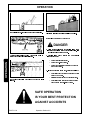
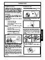
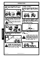
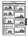
1
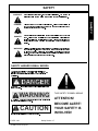
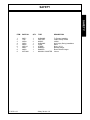
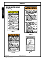
104QX ® Loader Part No. F-3672 Published 1/02 OPERATOR’S MANUAL This Operator’s Manual is an integral part of the safe operation of this machine and must be maintained with the unit at all times. READ, UNDERSTAND, and FOLLOW the Safety and Operation Instructions contained in this manual before operating the equipment. RHINO® 1020 S. Sangamon Ave. Gibson City, IL 60936 800-446-5158 Email: [email protected] © 2002 Alamo Group Inc. TO THE OWNER/OPERATOR/DEALER All implements with moving parts are potentially hazardous. There is no substitute for a cautious, safe-minded operator who recognizes the potential hazards and follows reasonable safety practices. The manufacturer has designed this implement to be used with all its safety equipment properly attached to minimize the chance of accidents. BEFORE YOU START!! Read the safety messages on the implement and shown in your manual. Observe the rules of safety and common sense! SAFETY HAZARD SIGNAL WORDS There are three levels of hazard intensity identified by signal words DANGER, WARNING and CAUTION. The level of hazard intensity is identified by the following definitions. DANGER - DANGER Immediate hazards which will result in severe injury or death. WARNING WARNING - Hazards or unsafe practices which could result in minor personal injury or death. CAUTION - CAUTION THIS SAFETY SYMBOL MEANS ATTENTION! BECOME ALERT! YOUR SAFETY IS INVOLVED! Hazards or unsafe practices which could result in minor personal injury or property damage. PELIGRO LEA EL INSTRUCTIVO Si No Lee Ingles, Pida Ayuda a Alguien Que Si Lo Lea Que le Traduzca las Medidas de Seguridad. Read and understand the complete Warranty Statement found in this Manual. Fill out the Warranty Registration Form in full and return it within 30 Days. Make certain the Serial Number of the Machine is recorded on the Warranty Card and on the Warranty Form that you retain. The use of will-fit parts will void your warranty and can cause catastrophic failure with possible injury or death. TO THE OWNER/OPERATOR/DEALER All implements with moving parts are potentially hazardous. There is no substitute for a cautious, safe-minded operator who recognizes the potential hazards and follows reasonable safety practices. The manufacturer has designed this implement to be used with all its safety equipment properly attached to minimize the chance of accidents. BEFORE YOU START!! Read the safety messages on the implement and shown in your manual. Observe the rules of safety and common sense! SAFETY HAZARD SIGNAL WORDS There are three levels of hazard intensity identified by signal words DANGER, WARNING and CAUTION. The level of hazard intensity is identified by the following definitions. DANGER - DANGER Immediate hazards which will result in severe injury or death. WARNING WARNING - Hazards or unsafe practices which could result in minor personal injury or death. CAUTION CAUTION - Hazards or unsafe practices which could result in minor personal injury or property damage. THIS SAFETY SYMBOL MEANS ATTENTION! BECOME ALERT! YOUR SAFETY IS INVOLVED! PELIGRO LEA EL INSTRUCTIVO Si No Lee Ingles, Pida Ayuda a Alguien Que Si Lo Lea Que le Traduzca las Medidas de Seguridad. Read and understand the complete Warranty Statement found in this Manual. Fill out the Warranty Registration Form in full and return it within 30 Days. Make certain the Serial Number of the Machine is recorded on the Warranty Card and on the Warranty Form that you retain. The use of will-fit parts will void your warranty and can cause catastrophic failure with possible injury or death. TABLE OF CONTENTS SAFETY SECTION . . . . . . . . . . . . . . . . . . . . . . . . . . . . . . . . . . . . . . . . . 1-1 Safety Precautions . . . . . Safety Hazard Signal Words Decal Locations . . . . . . Safety Decals. . . . . . . . . . . . . . . . . . . . . . . . . . . . . . . . . . . . . . . . . . . . . . . . . . . . . . . . . . . . . . . . . . . . . . . . . . . . . . . . . . . . . . . . . . . . . . . . . . . . . . . . . . . . . . . . . . . . . . . . . . . . . . . . . . . . . . . . 1-2 1-7 1-8 1-10 INTRODUCTION SECTION . . . . . . . . . . . . . . . . . . . . . . . . . . . . . . . . . . . . 2-1 Introduction . . . . . . . . . . . . . . . . . . . . . . . . . . . . . . . . . . . . . . . . . 2-2 Specifications. . . . . . . . . . . . . . . . . . . . . . . . . . . . . . . . . . . . . . . . 2-3 ASSEMBLY SECTION . . . . . . . . . . . . . . . . . . . . . . . . . . . . . . . . . . . . . . . 3-1 Assembly Instructions . . . . . . . . . . . . . . . . . . . . . . . . . . . . . . . . . . . 3-2 Dismounting Loader . . . . . . . . . . . . . . . . . . . . . . . . . . . . . . . . . . . . 3-3 Mounting Loader to Tractor. . . . . . . . . . . . . . . . . . . . . . . . . . . . . . . . . 3-4 OPERATION SECTION. . . . . . . . . . . . . . . . . . . . . . . . . . . . . . . . . . . . . . . 4-1 Preparting Tractor, Operating Loader, Filling Bucket. . . . . . . . . . Lifting Load, Carrying Load, Dumping Bucket, Lowering Bucket. . . . Operating Float Control, Loading From Bank . . . . . . . . . . . . . Peeling & Scraping, Loading Truck & Spreaders From Pile, Backfilling Handling Large Heavy Objects . . . . . . . . . . . . . . . . . . . . . Operating Grapple Fork . . . . . . . . . . . . . . . . . . . . . . . . . . . . . . . . . . . . . . . . . . . . . . . . . . . . . . . . . . . . . . . . . . . . . . . . . . . . . . . . . . . . 4-2 4-3 4-4 4-5 4-6 4-7 MAINTENANCE SECTION . . . . . . . . . . . . . . . . . . . . . . . . . . . . . . . . . . . . . 5-1 Cylinder Service . . . . . . . . . . . . . . . . Control Valve Service . . . . . . . . . . . . . Relief Valve. . . . . . . . . . . . . . . . . . . Self-Leveling Valve Service . . . . . . . . . . Daily Maintenance, Hydraulic Pressure Check. Hydraulic Trouble Shooting. . . . . . . . . . . Torque Chart . . . . . . . . . . . . . . . . . . . . . . . . . . . . . . . . . . . . . . . . . . . . . . . . . . . . . . . . . . . . . . . . . . . . . . . . . . . . . . . . . . . . . . . . . . . . . . . . . . . . . . Rhino is a registered trademark of Alamo Group Inc. . . . . . . . . . . . . . . . . . . . . . . . . . . . . . . . . . . . . . . . . . . . . . . . . . . . . . . . . . . . . . . . . . . . . . . 5-2 5-3 5-4 5-5 5-6 5-7 5-8 SAFETY SECTION Safety Section 1-1 . SAFETY SAFETY PRECAUTIONS A careful operator operates best. Most accidents can be SAFETY avoided by observing certain precautions. Read to help prevent accidents. Equipment should Stop loader arms gradually when lowering or lifting. 7. Use caution when handling loose or shiftable loads. 8. Carry bucket or attachment at a low position during transport 9. When for better visibility. all precautions that follow before operating your tractor and loader 6. be operated only by those who are responsible and instructed to 10. Operate do so. 11. Using 3. servicing, controls Replace damaged or illegible safety decals. See page 1-10 end large lower bucket to ground, stop only when properly seated at loaders heavy bales, without objects logs special such and attachments as oil large round drums is for or NOT RECOMMENDED. 12. Handling large heavy objects can be extremely dangerous for required decals. due to: Operate tractor and loader only from operator's seat. Danger of rolling tractor over. Danger of upending tractor. Danger of objects rolling or sliding down loader arms onto Use an approved roll bar and seat belt for safe operation. operator. Overturning a tractor without a rollbar can result in death or injury. If your tractor is not equipped with a rollbar and seat 13. If you must perform this sort of work (see 12 above), protect belt, see your Tractor Dealer. 2. front rectangular Read your Operator's Manuals carefully before using tractor TRACTOR 1. loader handling or loader. Lack of operating knowledge can lead to accidents. 2. or controls. GENERAL 1. parking engine and set park brakes before leaving tractor seat. Equip your tractor with yourself by: FOPS (Falling Object Protective Use proper attachments only. Never lift load higher than necessary to clear ground when Ballast tractor rear to compensate for load. Never lift large objects with equipment that does not have Move slowly and carefully, avoiding rough terrain. Structure) before installing or operating loader. 3. Always use seat belt when rollbar is installed. Do not use seat moving. belt if rollbar is removed from tractor. 4. Add recommended wheel ballast and/or rear weight as recommended in owner's manual to provide good stability. 5. Move rear wheels to widest settings recommended an anti-rollback device. to increase stability. 6. Move and turn tractor at low speeds. MAINTENANCE LOADER 1. 1. Improper use of a loader can cause serious injury or death. 2. Do not lift or carry anybody on loader, in bucket or etc., always use a drift and hammer of non-sparking material. Failure on Never allow anyone to get under loader bucket or reach 2. not so could result in injury from flying metal Do not modify or alter or permit anyone else to modify or alter first Do do loader or any of its components or any loader function without through lift arms when bucket is raised. 4. to fragments. attachment. 3. When servicing or replacing pins in cylinder ends, buckets, walk or work under a raised loader or bucket or consulting your Dealer. If you have regarding loader modifications contact any questions your Rhino Dealer. attachment unless it is securely blocked or held in position. 3. 5. Avoid overhead wires and obstacles when loader is raised. 6. Make sure all Always wear safety goggles when servicing or repairing tractor or loader. Contacting electric lines can cause electrocution. 4. parked loaders are on a hard, level surface. Escaping hydraulic/diesel fluid under pressure can penetrate skin causing serious personal injury. Engage all safety devices. OPERATING LOADER 1. DO NOT use your hand to check for leaks. Use a piece of cardboard or paper to search for leaks. As owner of this loader, it is your responsibility to be certain Stop engine and relieve pressure before connecting or disconnecting hydraulic or diesel lines. anyone operating this loader has read this manual first to be aware of safe operation of your tractor and loader. 2. Exercise caution when operating any loader with a raised 3. Avoid loose fill, rocks and holes. They can be dangerous for Tighten all connections before starting engine or pressurizing lines. loaded bucket or fork. If any fluid is injected into skin, obtain medical attention immediately or gangrene may result. loader operation or movement. 5. 4. Do not tamper with relief valve setting. Valve relief is factory- Use care when operating on steep grades to maintain proper set. stability. Always carry bucket or attachment as low Changing relief setting can cause overloading of as tractor or loader and serious operator injury may result. possible. 5. Allow for loader length when making turns. Whenever you see this symbol F-3672-1-02 It means: ATTENTION! BECOME ALERT! YOUR SAFETY IS INVOLVED! Safety Section 1-2 your SAFETY PELIGRO! Si no lee Ingles, pida ayuda a alguien que si Io lea para que Ie traduzca las medidas de seguridad. SAFETY DANGER! Never operate the Power Unit or Implement until you have read and completely understand this Manual, the Power Unit Operators Manual, and each of the Safety Messages found in the Manual or on the Power Unit and Implement. Learn how to stop the Power Unit engine suddenly in an emergency. Never allow inexperienced or untrained personnel too operate the Power Unit and Implement without supervision. Make sure the operator has fully read and understood the manuals prior to operation. WARNING! Always maintain the safety decals in good readable condition. If the decals are missing, damaged, or unreadable, obtain and install replacement decals immediately. WARNING! Make certain that the Slow Moving Vehicle (SMV) sign is installed in such a way as to be clearly visible and legible. When transporting the Equipment use the Power Unit flashing warning lights and follow all local traffic regulations. WARNING! Operate this Equipment only with a Tractor equipped with an approved roll-over-protective system (ROPS). Always wear seat belts. Serious injury or even death could result from falling off the tractorparticularly during a turnover when the operator could be pinned under the Operator Protective Structure. WARNING! Do not modify or alter this Implement. Do not permit anyone to modify or alter this Implement, any of its components or any Implement function. DANGER! BEFORE leaving the Power Unit seat, always engage the brake and/or set the Power Unit transmission in parking gear, disengage the auxiliary hydraulics, stop the engine, remove the key, and wait for all moving parts to stop. Place the Power Unit shift lever into a low range or parking gear to prevent the tractor from rolling. Never dismount a Power Unit that is moving or while the engine is running. Operate the Power Unit controls from the operator seat only. F-3672-1-02 Safety Section 1-3 SAFETY SAFETY DANGER! DANGER! Never allow children to operate or ride on the Power Unit or Implement. Do not mount the Power Unit while the Power Unit is moving. Mount the Power Unit only when the Power Unit and all moving parts are completely stopped. DANGER! Start the Power Unit only when properly seated in the Power Unit seat. Starting a Power Unit in gear can result in injury or death. Read the Power Unit operator's manual for proper starting instructions. DANGER! Never work under the Implement, the framework, or any lifted component unless the Implement is securely supported or blocked up to prevent sudden or inadvertent falling which could cause serious injury or even death. WARNING! The operator and all support personnel should wear hard hats, safety shoes, safety glasses, and proper hearing protection at all times for protection from injury including injury from items thrown by the equipment. WARNING! PROLONGED EXPOSURE TO LOUD NOISE MAY CAUSE PERMANENT HEARING LOSS! Tractors with or without an Implement attached can often be noisy enough to cause permanent hearing loss. We recommend that you always wear hearing protection if the noise in the Operators position exceeds 80db. Noise over 85db over an extended period of time will cause severe hearing loss. Noise over 90db adjacent to the Operator over an extended period of time will cause permanent or total hearing loss. Note: Hearing loss from loud noise [from tractors, chain saws, radios, and other such sources close to the ear] is cumulative over a lifetime without hope of natural recovery F-3672-1-02 © 2001 Alamo Group Inc. Safety Section 1-4 SAFETY DANGER! Do not operate this Equipment with hydraulic oil leaking. Oil is expensive and its presence could present a hazard. Do not check for leaks with your hand! Use a piece of heavy paper or cardboard. High- pressure oil streams from breaks in the line could penetrate the skin and cause tissue damage immediately by a physician knowledgeable and skilled in this procedure. DANGER! Transport only at safe speeds. Serious accidents and injuries can result from operating this equipment at unsafe speeds. Understand the Power Unit and Implement and how it handles before transporting on streets and highways. Make sure the Power Unit steering and brakes are in good condition and operate properly. Before transporting the Power Unit and Implement, determine the safe transport speeds for you and the equipment. Make sure you abide by the following rules: 1. Test the Power Unit at a slow speed and increase the speed slowly. Apply the Brakes smoothly to determine the stopping characteristics of the Power Unit and Implement. As you increase the speed of the Power Unit the stopping distance increases. Determine the maximum safe transport speed for you and this Equipment. 2. Test the equipment at a slow speed in turns. Increase the speed through the turn only after you determine that it is safe to operate at a higher speed. Use extreme care and reduce your speed when turning sharply to prevent the Power Unit and Implement from turning over. Determine the maximum safe turning speed for you and this equipment before operating on roads or uneven ground. 3. Only transport the Power Unit and Implement at the speeds that you have determined are safe and which allow you to properly control the equipment. Be aware of the operating conditions. Do not operate the Power Unit with weak or faulty brakes. When operating down a hill or on wet or rain slick roads, the braking distance increases: Use extreme care and reduce your speed. When operating in traffic always use the Power Unit's flashing warning lights and reduce your speed. Be aware of the traffic around you and watch out for the other guy. WARNING! Never attempt to lubricate, adjust, or remove material from the Implement while it is in motion or while Power Unit engine is running. Make sure the Power Unit engine is off before working on the Implement! WARNING! Periodically inspect all moving parts for wear and replace when necessary with authorized service parts. Look for loose fasteners, worn or broken parts, and leaky or loose fittings. Make sure all pins have cotter pins and washers. Serious injury may occur from not maintaining this machine in good working order. F-3672-1-02 Safety Section 1-5 SAFETY including gangrene. If oil does penetrate the skin, have the injury treated SAFETY SAFETY WARNING! Always read instructions carefully when and handling comply oil, fully solvents, with the cleansers, manufacturers and any other chemical agent. DANGER! Never run the Power Unit engine in a closed building or without adequate ventilation. The exhaust fumes can be hazardous to your health. DANGER! KEEP AWAY FROM ROTATING ELEMENTS to prevent entanglement and possible serious injury or death. DANGER! Never allow children to play on or around Power Unit or Implement. Children can slip or fall off the Equipment and be injured or killed. Children can cause the Implement to shift or fall crushing themselves or others. WARNING! Do not exceed the rated PTO speed for the Implement. Excessive PTO speeds can cause Implement driveline ailures resulting in serious injury. DANGER! NEVER use drugs or alcohol immediately before or while operating the Power Unit and Implement. Drugs and alcohol will affect an operators alertness and coordination and therefore affect the operators ability to operate the equipment safely. Before operating the Power Unit or Implement, an operator on prescription or over-the-counter medication must consult a medical professional regarding any side effects of the medication that would hinder their ability to operate the Equipment safely. NEVER knowingly allow anyone to operate this equipment when their alertness or coordination is impaired. Serious injury or death to the operator or others could result if the operator is under the influence of drugs or alcohol. DANGER! Operate the Power Unit and/or Implement controls only while properly seated in the operator's seat with the seat belt securely fastened around you. Inadvertent movement of the Power Unit or Implement may cause serious injury or death. F-3672-1-02 © 2001 Alamo Group Inc. Safety Section 1-6 SAFETY WARNING! Never interfere with factory-set hydraulic calibrations. Any change in calibration could cause a failure of the equipment and result in injury. Always shut the Power Unit completely down, place the transmission in park, and set the parking brake before you or anyone else attempts to connect or disconnect the Loader. DANGER! Never crawl under a raised implement supported solely by the Power Unit boom. Release of the control lever or mechanical failure will result in the Implement falling and possible injury or death. Always securely block up the Implement before crawling underneath to perform repairs and service. WARNING! Relieve hydraulic pressure prior to doing any maintenance or repair work on the implement. Place the Loader on the ground or securely supported on blocks or stands, disengage the auxiliary hydraulics and turn off engine. Push and pull the control levers several times to relieve pressure prior to starting any maintenance or repair work. SAFETY HAZARD SIGNAL WORDS There are three levels of hazard intensity identified by signal words DANGER, WARNING and CAUTION. The level of hazard intensity is identified by the following definitions. ! DANGER - Immediate hazards which will result in severe injury or death. WARNING WARNING - Hazards or unsafe practices which could result in minor personal injury or death. CAUTION CAUTION - Hazards or unsafe practices which could result in minor personal injury or property damage. F-3672-1-02 © 2001 Alamo Group Inc. Safety Section 1-7 THIS SAFETY SYMBOL MEANS ATTENTION! BECOME ALERT! YOUR SAFETY IS INVOLVED! SAFETY DANGER! SAFETY SAFETY 5 6 6 2 8 1 3 3 7 4 RIGHT SIDE FRAME LEFT SIDE FRAME 9 9 F-3672-1-02 © 2001 Alamo Group Inc. Safety Section 1-8 SAFETY SAFETY ITEM PART NO. QTY. TYPE DESCRIPTION 1 2 3 4 5 6 7 8 9 26871 7794 38789 36932 49696 35674-6 48921 48858 00776481 1 1 2 1 2 1 1 1 1 WARNING CAUTION MODEL WARNING LOGO STRIPE DANGER DANGER MANUAL CANISTER To Prevent Instability Loader Safety Guides 104QX Avoid Injury During Installation Rhino Silver, 13.5 ft. Stability Danger Electric Shock Danger 2 items F-3672-1-02 Safety Section 1-9 SAFETY NOTE: Safety decal location is listed below each decal. illegible. Replace Replacement decal if decals damaged are or available SAFETY from your dealer. 2 - - 7794 1 - - 26871 DANGER 7- - 48921 4 - - 36932 F-3672-1-02 © 2001 Alamo Group Inc. Safety Section 1-10 SAFETY SAFETY 3 - - 38789 6 - - 35674-6 ® 49696 5 - - 49696 9 - - 00776481 DANGER Keep bucket and boom away from overhead electric lines. Failure to comply will result in serious injury or death. 8 - - 48858 F-3672-1-02 Safety Section 1-11 SAFETY SAFETY FEDERAL LAWS AND REGULATIONS This section is intended to explain in broad terms the concept and effect of federal laws and regulations concerning employer and employee equipment operators. This section is not intended as a legal interpretation of the law and should not be considered as such. Employer-Employee Operator Regulations U.S. Public Law 91-596 (The Williams-Steiger Occupational and Health Act of 1970) OSHA This Act Seeks: “...to assure so far as possible every working man and woman in the nation safe and healthful working conditions and to preserve our human resources...” DUTIES Sec. 5 (a) Each employer(1) shall furnish to each of his employees employment and a place of employment which are free from recognized hazards that are causing or are likely to cause death or serious physical harm to his employees; (2) shall comply with occupational safety and health standards promulgated under this Act. (b) Each employee shall comply with occupational safety and health standards and all rules, regulations and orders issued pursuant to this Act which are applicable to his own actions and conduct. OSHA Regulations OSHA regulations state in part: “At the time of initial assignment and at least annually thereafter, the employer shall instruct every employee in the safe operation and servicing of all equipment with which the employee is, or will be involved.” Employer Responsibilities: To ensure employee safety during Tractor and Implement operation, it is the employer’s responsibility to: 1. Train the employee in the proper and safe operation of the Tractor and Implement. 2. Require that the employee read and fully understand the Tractor and Implement Operator’s manual. 3. Permit only qualified and properly trained employees to operate the Tractor and Implement. 4. Maintain the Tractor and Implement in a safe operational condition and maintain all shields and guards on the equipment. 5. Ensure the Tractor is equipped with a functional ROPS and seat belt and require that the employee operator securely fasten the safety belt and operate with the ROPS in the raised position at all times. 6. Forbid the employee operator to carry additional riders on the Tractor or Implement. 7. Provide the required tools to maintain the Tractor and Implement in a good safe working condition and provide the necessary support devices to secure the equipment safely while performing repairs and service. 8. Require that the employee operator stop digging if bystanders or passerbys come within 10 yards. Child Labor Under 16 Years of Age Some regulations specify that no one under the age of 16 may operate power machinery. It is your responsibility to know what these regulations are in your own area or situation. (Refer to U.S. Dept. of Labor, Employment Standard Administration, Wage & Home Division, Child Labor Bulletin #102.) F-3672-1-02 © 2001 Alamo Group Inc. Safety Section 1-12 INTRODUCTION SECTION Introduction Section 2-1 INTRODUCTION INTRODUCTION INTRODUCTION This manual provides operation, maintenance, assembly and parts identification for your new loader. Your loader has been designed to give many years of satisfactory service. Successful operation and long life of the loader depends on proper maintenance and operation. Please read this manual carefully and follow all instructions. Correct assembly, operation and maintenance will save you much time and expense. Also follow instructions included with loader mounting and hydraulic kits to insure that loader is installed correctly to tractor. NOTE: This safety alert symbol identifies important safety messages in this manual. Observe and follow all safety messages to prevent personal injury. Reference to left-hand and right-hand used in this manual refers to position of operator when seated in the operating position of loader. If at any time you have a service problem with your loader or need new parts, contact your local dealer. Your dealer will need your loader model number and serial number to give you prompt efficient service. Parts orders must give complete description, correct part number, total amount required, model number, all necessary serial numbers, method of shipment and shipping address. F-3672-1-02 © 2001 Alamo Group Inc. Introduction Section 2-2 INTRODUCTION SPECIFICATIONS Specifications will vary with tractor, tire size, hydraulic system and bucket used. The specifications are given for a loader equipped with 72" HD material bucket operated with an average tractor hydraulic system of 20 GPM with engine operating at 2200 RPM and control valve relief setting of 2200 PSI. Break-away Capacity . . . . . . . . . . . . . . . . . . . . . . . . . . . . . 3770# Lift capacity at Full Height . . . . . . . . . . . . . . . . . . . . . . . . . . . 2240# Raising Time . . . . . . . . . . . . . . . . . . . . . . . . . . . . . . . . . 4.5 sec. Lowering Time . . . . . . . . . . . . . . . . . . . . . . . . . . . . . . . . 3.2 sec. Attachment Dumping Time. . . . . . . . . . . . . . . . . . . . . . . . . . . 2.7 sec. Attachment Rollback Time . . . . . . . . . . . . . . . . . . . . . . . . . . . 1.9 sec. Lift Cylinder: . . . . . . . . . . . . . . . . . . . . . . . . . . . . . . . . . 2.00 in Stroke . . . . . . . . . . . . . . . . . . . . . . . . . . . . . . . . 22.69 in. Piston Diameter . . . . . . . . . . . . . . . . . . . . . . . . . . . . 2.75 in. Rod Diameter . . . . . . . . . . . . . . . . . . . . . . . . . . . . . 1.5 in. Bucket Cylinder: . . . . . . . . . . . . . . . . . . . . . . . . . . . . . . . . 2.25 in. Stroke . . . . . . . . . . . . . . . . . . . . . . . . . . . . . . . . 19.62 in. Piston Diameter . . . . . . . . . . . . . . . . . . . . . . . . . . . . 2.25 in. Rod Diameter . . . . . . . . . . . . . . . . . . . . . . . . . . . . . 1.375 in. (A) Maximum Clearance At Full Height . . . . . . . . . . . . . . . . . . . . . 119 in. (B) Clearance with Bucket Dumped . . . . . . . . . . . . . . . . . . . . . . 93 in. (C) Reach at Maximum Height . . . . . . . . . . . . . . . . . . . . . . . . . 48 in. (D) Maximum Dump Angle . . . . . . . . . . . . . . . . . . . . . . . . . . . 47° (E) Reach with Attachment on ground . . . . . . . . . . . . . . . . . . . . . 80 in. (F) Attachment Rollback Angle. . . . . . . . . . . . . . . . . . . . . . . . . 21° (G) Digging Depth . . . . . . . . . . . . . . . . . . . . . . . . . . . . 12 in. (H) Overall Height in Carry Position . . . . . . . . . . . . . . . . . . . . . . 77 in. (Manufacturers estimated specifications and design subject to change without notice.) F-3672-1-02 Introduction Section 2-3 INTRODUCTION Weight w/72" Heavy Duty Bucket. . . . . . . . . . . . . . . . . . . . . . . . 1910# ASSEMBLY SECTION Assembly Section 3-1 ASSEMBLY ASSEMBLY INSTRUCTIONS INSTALLING BUCKET Attach bucket to the lift boom frame and bucke? cylinders INSTALLING MOUNTING BRACKETS with 1-1/4 x 5-1/2 pins (9). 3/8 x 1" shoulder bolts (15) and Install all mounting brackets on the tractor according to lock nuts (20). instructions packed with mounting kit. INSTALLING BUCKET LEVEL INDICATOR INSTALLING LOADER Attach indicator guide tube (11) to the knee plate on the Install loader onto mounting brackets on tractor according right side of lift boom frame (1) with 3/8 lock nuts (20). to instructions packed with mounting kit. NOTE: Leave lock nuts loose enough so tube rotates INSTALLING GREASE FITTINGS freely. Install 1/4 straight grease fittings (23) into the rod end of Slide bucket level indicator rod (10) into the guide tube bucket cylinders. and attach the other end of rod to the bucket with 1/8 x 1" NOTE: Grease fittings should point up ward when rod ends are attached to bucket. cotter pins (21). Locate tractor and loader on level surface. With the bottom of bucket resting on surface, cut off the excess rod ASSEMBLY (10) flush with the end of guide tube (11). 29 28 34 35 33 35 32 34 31 25 24 26 27 F-3632-10-01 Assembly Section 3-2 30 ASSEMBLY DISMOUNTING AND MOUNTING LOADER mounting bracket and mid mounting brackets. This can also be accomplished by using the boom float IMPORTANT: position if the valve used to control the lift cylinders is The loader must be equipped with a so bucket to dismount the loader from the tractor. equipped. disengage NOTE: The loader should be stored in a dry place. Move front the support tractor bracket backwards tube from to front mounting bracket channel. Activate lift control lever to gently lower loader front support bracket to the ground. Continue rotating loader side frames off mid 1. Locate the tractor on firm level ground. 2. Level the bucket and lower it to the ground. Engage the mounting brackets until hinges clear mid mounting tubes. Slowly back tractor out of loader while rotating loader tractor brakes and shut off the tractor engine. Move the pressure in the lift cylinders. 3. closed around the mid mounting The the extra threads provided on the hinge carriage bolt. Remove the rubber strap which secures the hoses to bracket. Remove any tie straps which attach hoses to tractor or brackets. 5. Start the tractor engine and release tractor brakes. Lower loader boom slightly as necessary to distribute the weight of the loader equally between the front F-3672-1-02 fully tractor may have to be moved forward or Engage tractor brakes and shut off tractor engine. open. The lock nut can be stored by fastening it onto support are hydraulic hoses. provided in side frame upright so hinge will be blocked front cylinders backward while collapsing loader to maintain slack in wide as possible, insert cap screw through the hole loader lift and bucket cylinders to their fully collapsed position. tubes. washer onto cap screw, and holding hinge open as the until period of time (once a month or more) retract the lift Remove cap screws, washers and lock nuts. Place 4. frames NOTE: If the loader is being stored for an extended Loosen the 3/4 x 3-1/2 cap screws which clamp the hinges side extended. lift control lever back and forth several times to relieve 6. Move lift and bucket control levers back and forth several times to relieve pressure on the lift and bucket cylinders. Disconnect quick couplers between the loader and tractor. Hang hoses over the side frame for storage. If tractor is equipped with the optional 1 lever auxiliary valve, also remove the valve support assembly from the guide tube on right mid mounting bracket. Slide valve support assembly into bracket provided on underside of right side frame channel. Assembly Section 3-3 ASSEMBLY DISMOUNTING LOADER ASSEMBLY PREPARING STORED LOADER FOR MOUNTING MOUNTING PROCEDURE If the loader has been completely collapsed for long-term The storage, it is necessary to expand the loader first, before it dismounting mounting procedure is basically the reverse of can be mounted on the tractor. Follow the instructions below which apply to your loader, depending on what 1. Slowly drive the tractor up to loader until hoses will valve is used to control the loader, to prepare the loader reach from the loader to the tractor. Engage the tractor for mounting brakes and shut off tractor engine. FOR LOADER PLUMBED TO TRACTOR REMOTE VALVE 1. 2. 2. Connect quick couplers between tractor and loader, matching color coded bands. Slowly back the tractor up to the loader until hoses will NOTE: reach from loader to tractor remote couplers. Engage sure hinges are blocked open wide by 3/4 x 3-1/2 cap the tractor brakes and shut off the tractor engine. screws in hole provided in each side frame upright. Making sure quick couplers are clean, connect quick 3. Start tractor engine and release tractor brakes. Slowly couplers between the tractor and loader. Match color drive the tractor ahead while activating lift control lever coded bands when connecting couplers. to retract lift cylinders. Position tractor so hinges hook mid 3. Make sure quick couplers are clean, and make Start the tractor engine and release tractor brakes. mounting bracket tubes as loader side frame uprights rotate. Operate the lift control valve to extend the lift cylinders as far as possible. 4. Put the tractor in neutral. Retract the lift cylinders ASSEMBLY bringing the side frame channels up so front support NOTE: The tractor may have to be moved backward or bracket tube contacts front mounting bracket channel. forward while extending lift cylinders to maintain slack in Move the tractor ahead so front support bracket tube hydraulic hoses. engages in front mounting bracket channel and loader side frame uprights seat properly on mid mounting 4. Once the lift cylinders are fully extended, shut off the bracket tubes (with no gap between upright cut-out tractor engine and engage the tractor brakes. Move and front of tube). Engage tractor brakes and shut off the loader control levers back and forth to relieve tractor engine. pressure in the cylinders, then disconnect the quick couplers. 5. Remove 3/4 x 3-1/2 cap screw with washer which blocked hinge open and remove elastic lock nut from 5. Start the tractor engine, release the tractor brakes extra threads on hinge carriage bolt. Clamp hinge of slowly drive the tractor up to loader upright around the mid mounting tube. Insert 3/4 x 31/2 cap screw down through upright and hinge and FOR LOADER PLUMBED TO fasten washer and elastic nut onto cap screw outside OPTIONAL 1-LEVER AUXILIARY VALVE 1. of hinge. Slowly drive the tractor up to the loader until hoses will reach from 1 -lever auxiliary valve to tractor. Engage tractor brakes and shut off tractor engine. 2. Reinstall support valve guide support tube. assembly Connect into quick IMPORTANT: clamp hinge. 3. the valve couplers by 6. nut against hinge Hook the rubber strap from hoses to loader support Make sure quick couplers are clean. Operate lift control to extend the lift cylinders as far as possible. The tractor may have to be moved backward or forward while extending lift cylinders to maintain slack in hydraulic hoses. F-3672-1-02 lock bracket. Reinstall reusable tie straps. Start the tractor engine and release tractor brakes. NOTE: elastic securely, but to no more than 125 ft-lbs. torque. matching color coded bands. NOTE: Be sure to use ELASTIC lock nut to Tighten Assembly Section 3-4 OPERATION SECTION Operation Section 4-1 OPERATION PREPARING TRACTOR Loaders with 2-lever controls, ease both levers back to lift Before operating loader, for optimum stability, additional and roll back bucket. weight should be added to rear of tractor with rear wheel weights or liquid ballast. Refer to your tractor operator's manual for weighting information. The tractor rear wheels should be moved to the tractor manufacturer's widest recommended settings to increase the stability of the tractor. OPERATING LOADER Lift Loader should be operated with tractor engine running at and roll back of bucket will increase efficiency because... 1500-1800 RPM. Excessive speeds are dangerous and may cause bucket spillage and unnecessary strain on the tractor and loader. When operating in temperatures below 30º F., run the tractor engine below 1200 rpm until oil temperature exceeds 30º F. The following text and illustrations offer suggested loader and tractor operating techniques. ... A level bucket throughout the lifting cycle resists bucket lift and increases breakaway effort. FILLING THE BUCKET OPERATION Approach and enter the pile with a level bucket. NOTE: Do not be concerned if the bucket is not Loaders with 1-lever control, ease lever back and away completely filled during each pass. Maximum productivity from you to lift and roll back bucket. is determined by the amount of material loaded in a given period of time. Time is lost if two or more attempts are made to fill the bucket on each pass. F-3672-1-02 Operation Section 4-2 OPERATION LIFTING THE LOAD When When lifting the load, keep the bucket positioned to avoid transporting the load, keep bucket as low as possible, to avoid tipping, in case a wheel drops in a rut. spillage. DUMPING THE BUCKET Lift bucket high enough to clear side of vehicle. Move tractor in as close as possible to side of vehicle, then dump bucket. CAUTION: Do not attempt to lift loads in excess of loader capacity. CARRYING THE LOAD Position bucket just below tractor hood for maximum stability and visibility, whether bucket is loaded or empty. LOWERING THE BUCKET lowering and rolling back bucket. Use extreme care when operating loader on a slope, keep bucket as low as possible. This keeps center of gravity low and will provide maximum stability. CAUTION: Operating loader on a hillside is dangerous. Extreme care is recommended. Keep bucket as low as possible. F-3672-1-02 Operation Section 4-3 OPERATION After bucket is dumped, back away from vehicle while OPERATION OPERATING WITH FLOAT CONTROL During hard surface operation, keep bucket level and put lift control in float position to permit bucket to float on working surface. If hydraulic down pressure is exerted on bucket, it will wear faster than normal. Sidecutting is a good technique for cutting down a big pile. Float will also prevent mixing of surface material with stockpile material. Float positionwill reduce the chance of surface gouging when removing snow or other material, or when working with a blade. If the pile sides are too high and liable to cause cave-in, use loader to break down the sides until a slot can be cut OPERATION over the top. LOADING FROM A BANK Choose a forward gear that provides sufficient ground speed for loading. Another method for large dirt piles is to build a ramp approach to the pile. Exercise caution when undercutting high banks. Dirt slides can be dangerous. Load from as low as possible for maximum efficiency. Loader lift and breakoaway capacity diminish as loading height is increased. It is important to keep the bucket level when approaching a bank or pile. This will help prevent gouging the work area. F-3672-1-02 Operation Section 4-4 OPERATION PEELING AND SCRAPING Use a slight bucket angle, travel forward and hold lift control forward to start the cut. Make a short 5 to 8 foot Backgrade occasionally with a loaded bucket to keep working surface free of ruts and holes. Also, hold lift control forward so full wieght of bucket is scraping ground. angle cut and break out cleanly. BACKFILLING With bucket level, start a cut at notch approximately 2 inches deep. Hold depth by feathering bucket control to adjust cutting lip up or down. When front tires enter the notch, adjust lify cylinder to maintain proper depth. Make additional passes until desired depth is reached. During each pass, use only bucket control while working depth. This will allow you to concentrate on controlling bucket angle to maintain a precise cut. LOADING LOW TRUCKS OR SPREADERS FROM A PILE Poor methods actually move no more dirt and make it more difficult to hold a level grade. Do not use bucket in dumped position for bulldozing. This method, shown above, will impose severe shock loadings on dump linkage, bucket cylinder and tractor. For faster loading, minimize angle of turn and length of run between pile and spreader. F-3672-1-02 Operation Section 4-5 OPERATION Approach pile with a level bucket. OPERATION Leave dirt in bucket. Dumping on each pass wastes time. Pile dirt on high side for easier backfilling on a slope. HANDLING LARGE HEAVY OBJECTS DANGER 1. Using front end loaders for handling large heavy objects such as large round or rectangular bales, logs and oil drums is not recommended. Operate at right angles to ditch. Take as big a bite as 2. tractor can handle without lugging down. Handling large heavy objects can be extremely dangerous due to: OPERATION • • • Danger of rolling tractor over. Danger of up-ending tractor. Danger of object rolling or sliding down loader arms onto operator. 3. If you must perform above work, protect yourself by: • Never lifting load higher than necessary to clear ground when moving. Leave dirt cleanup. which drifts over side of bucket for final • • Ballasting tractor rear to compensate for load. Never lifting large objects with equipment that does not have an anti-rollback device. SAFE OPERATION IS YOUR BEST PROTECTION AGAINST ACCIDENTS F-3672-1-02 Operation Section 4-6 OPERATION GRASPING ROUND BALES OPERATING GRAPPLE FORK Operation of your tractor and loader with grapple fork Approach bale with grapple fork open and bucket level. option Use loader float position if bale is on ground. requires some same basic considerations as operation with a bucket, plus two new requirements: you now have to operate a grapple fork while already operating your tractor and loader; and you must also take into account additional space requirements (added length and height) needed because of attached grapple fork. INTENDED USE Use of this loader without special attachments for handling large heavy objects such as large round or rectangular bales, logs and oil drums NOT is RECOMMENDED. Ease valve control lever for grapple fork forward to close Handling large heavy objects can be extremely grapple fork around bale. dangerous due to: • • • Danger of rolling tractor over. Danger of upending tractor. Danger of objects rolling or sliding down loader arms onto operator. If you must perform any work listed above, protect yourself by: • Never lift load higher than necessary to clear ground when moving. NOTE: While large round bales are best grasped as shown above, they may also be grasped from either side Ballast tractor rear to compensate for load. if necessary. DO NOT ATTEMPT TO LIFT MORE THAN Never lift large objects with equipment that ONE LARGE ROUND BALE AT A TIME as this can cause does not have an anti-rollback device. • overloading of loader or tractor or cause unstable conditions. Move slowly and carefully, avoiding rough terrain. LIFTING AND CARRYING LOAD Using special attachments as shown, and exercising caution, your loader can be used to handle large round or Ease both loader control levers back to lift and roll bucket back. rectangular bales and loose bulky materials like hay and silage. Do not attempt to use loader to handle logs, fertilizer bags or liquid containers since such use is NOT RECOMMENDED. NOTE: It is recommended to use both tine clamps if your grapple fork is to be used for handling round or rectangular bales. Using only one clamp may work better for loose hay or silage, allowing tines to penetrate better. Additional tine clamps are optional. Keep each grapple fork tine clamp securely fastened to grapple fork tines at all times. F-3672-1-02 Operation Section 4-7 OPERATION • • OPERATION Position bucket just below level of tractor hood for maximum stability and visibility whether bucket is loaded or empty. LOADING INTO TUB GRINDER Lift bucket high enough to clear tub grinder sides. Move tractor toward tub grinder to position load near center. Extend bucket cylinders to position bucket in dump attitude. Use extreme care when operating loader on a slope. Carry load as low as possible. This keeps center of gravity for bale, tractor and loader low and will provide maximum Gradually open grapple fork tines, allowing material to tractor stability. drop into tub grinder. For round bales it may be necessary CAUTION: Operating a loader on a hillside is dangerous. Extreme care is recommended to to gradually set bale into tub grinder to avoid shock loading tub grinder due to bale weight and to avoid sudden load on grinder mechanism. OPERATION avoid overturns. Roll bucket back, close grapple fork and back tractor away from tub grinder, then lower loader boom after Even on level ground, transport bucket and load as low as possible to avoid tipping in case a wheel drops in a rut and to avoid power lines. dumping. STACKING BALES WARNING: Because of size and weight of large bales, extreme care must be taken in handling them. Be aware of forces acting on stacked bales due to gravity and keep workers far from zones of potential hazard from shifting or falling ALLOW BYSTANDERS! WARNING: Keep bucket, grapple fork and loader boom clear of overhead lines. Allowing loader boom or any attachments to contact overhead power lines may electrify entire tractor and electrocute (kill) operator. F-3672-1-02 Operation Section 4-8 bales. DO NOT OPERATION Use loader and grapple fork to gently position bale on An alternative method is to use your loader and grapple stack, then release bale while removing bucket and fork. fork to knock material down from top of pile so it can be loaded from ground. Slowly back tractor away from stack. Exercise caution when undercutting a high pile. Avalanching material can be dangerous. LOADING FROM A STACK, BUNKER SILO OR PIT SILO Choose a forward gear that provides sufficient ground When loading material from ground, keep a level bucket speed for loading. and use lift control float position. If hydraulic down pressure is exerted on a bucket, it will wear faster than OPERATION normal. Keep bucket level when approaching pile. Touch pile as near as possible to top with bucket positioned in dump attitude and grapple fork open. Close grapple fork while maneuvering bucket to grasp loose material. CAUTION: capacity Keeping a level bucket and using loader float will reduce Loader diminish lift as and loader break-away height is surface gouging and mixing surface material with stockpile material. increased. Care must be taken not to grasp more material than your loader can safely support. When a sufficient amount of material has accumulated in front of bucket, close grapple fork to grasp material and curl bucket back. F-3672-1-02 Operation Section 4-9 MAINTENANCE SECTION Maintenance Section 5-1 MAINTENANCE MAINTENANCE F-3672-1-02 Maintenance Section 5-2 MAINTENANCE MAINTENANCE F-3672-1-02 Maintenance Section 5-3 MAINTENANCE MAINTENANCE F-3672-1-02 Maintenance Section 5-4 MAINTENANCE MAINTENANCE remove F-3672-1-02 © 2001 Alamo Group Inc. Maintenance Section 5-5 MAINTENANCE Regular maintenance of your loader and hydraulic system HYDRAULIC PRESSURE CHECK will insure maximum loader efficiency and long life. Following procedure outlines hydraulic pressure check. WARNING: beneath a properly NEVER raised perform loader supported to maintenance unless loader prevent is 1. accidental Obtain a pressure gauge that measures 3000PSI in 50 PSI increments. lowering. 2. DAILY MAINTENANCE • Install gauge into the hydraulic line connecting the loader valve and to the base port of bucket cylinders. Check fluid level of tractor hydraulic system 3. Start engine and adjust to 1500-1800 RPM. before starting each day's operation. If necessary, add hydraulic oil as recommended 4. • Push bucket control lever to pressurize the hydraulic line with the gauge attached. Hold the control until the in your tractor operator's manual. cylinders reach the fully extended position. Holding After every eight hours of operation, lubricate all the control with cylinders fully extended will give you twelve grease fittings: one at each end of lift the hydraulic system pressure on the gauge. boom arms and one at rod and base ends of each lift and bucket cylinder. • 5. After every ten hours of operation, check all hardware and tighten where required. • If pressure or contact your dealer. Replace hoses immediately if they are damaged by a cut or scrape, extruded at the fittings or leaking. Hydraulic oil leaks should be repaired promptly to avoid loss of oil and serious personal injury from escaping oil. WARNING: Use a piece of wood or cardboard rather than hands and wear eye protection when searching for hydraulic leaks. Escaping hydraulic oil under pressure can sufficient force to penetrate the skin. MAINTENANCE fluid is injected into skin, obtain have If any medical attention immediately or gangrene may result. F-3672-1-02 is not correct, refer to "TROUBLESHOOTING" section for possible remedy Maintenance Section 5-6 MAINTENANCE MAINTENANCE set screw. F-3672-1-02 © 2001 Alamo Group Inc. Maintenance Section 5-7 MAINTENANCE GENERAL TORQUE SPECIFICATIONS USE THE FOLLOWING TORQUES WHEN SPECIAL TORQUES ARE NOT GIVEN AMERICAN STANDARD CAP SCREWS SAE 5 8 Metric Class 8.8 10.9 TORQUE TORQUE Cap Screw TORQUE TORQUE Grade Cap Screw MAINTENANCE Size METRIC CAP SCREWS FT-LBS Nm FT-LBS Nm Size FT-LBS Nm FT-LBS Nm Inches MIN MAX MIN MAX MIN MAX MIN MAX Millimeters MIN MAX MIN MAX MIN MAX MIN 1/4-20 6.25 7.25 8.5 10 8.25 9.5 11 13 M6x100 6 8 8 11 9 11 12 MAX 15 1/4-28 8 9 11 12 10.5 12 14 16 M8 x 1.25 16 20 215 27 23 27 31 36.5 5/16 - 18 14 15 19 20 18.5 20 25 27 M10 x 1.50 29 35 39 47 42 52 57 70 5/16 - 24 17.5 19 23 26 23 25 31 34 M12 x 1.75 52 62 70 84 75 91 102 123 3/8 - 16 26 28 35 38 35 37 47.5 50 M14 x 2.00 85 103 115 139 120 146 163 198 3/8 - 24 31 34 42 46 41 45 55.5 61 M16 x 2.50 130 158 176 214 176 216 238 293 7/16 - 14 41 45 555 61 55 60 74.5 81 M18 x 2.50 172 210 233 284 240 294 325 398 7/16 - 20 51 55 69 745 68 75 92 102 M20 x 2.50 247 301 335 408 343 426 465 577 ½ - 13 65 72 88 975 86 96 116 130 M22 x 2.50 332 404 450 547 472 576 639 780 ½ - 20 76 84 103 114 102 112 138 152 MM24 x 3.00 423 517 573 700 599 732 812 992 9/16 - 12 95 105 129 142 127 140 172 190 M27 x 3.00 637 779 863 1055 898 1098 1217 1488 M30 x 3.00 872 1066 1181 1444 1224 1496 1658 2027 9/16 - 18 111 123 150 167 148 164 200 222 5/8 - 11 126 139 171 188 168 185 228 251 5/8 - 18 152 168 206 228 203 224 275 304 ¾ - 10 238 262 322 355 318 350 431 474 ¾ - 16 274 305 371 409 365 402 495 544 7/8 - 9 350 386 474 523 466 515 631 698 7/8 -14 407 448 551 607 543 597 736 809 1 - 8 537 592 728 802 716 790 970 1070 1 - 14 670 740 908 1003 894 987 1211 1337 NOTE: These values with normal engine -4 Size ft. lb. Connection F.F.F.T. 7/16-20 140 ± 10 12 ± 1 -5 1/2-20 180 ± 15 15 ± 1 -6 9/16-18 250 ± 15 21 ± 1 as oil. They do not apply if Torque Specifications for SAE O-Ring Fittings Assembly Torque Tube in. lb. fasteners other extreme pressure lubricants are used. Assembly Torque Thread to special graphite or molydisulphide greases or Torque Specifications for 37º JIC Fittings Size apply received from the supplier, dry or when lubricated Swivel Nut or Hose Connection Size Thread Size in. lb. ft. lb. F.F.F.T. F.F.F.T. 2 5/16-24 90 ± 5 7.5 ± 0.5 1 ± .25 2 3 3/8-24 170 ± 10 14 ± 1 1 ± .25 2 2 4 7/16-20 220 ± 15 18 ± 1 1 ± .25 1 1/2 1 1/4 5 1/2-20 260 ± 15 22 ± 1 1 ± .25 2 -8 3/4-16 550 ± 25 45 ± 5 1 1/2 1 6 9/16-18 320 ± 20 27 ± 2 1.5 ± .25 -12 1 1/16-12 1000 ± 50 85 ± 5 1 1/4 1 8 3/4-16 570 ± 25 48 ± 2 1.5 ± .25 -16 1 5/16-12 1450 ± 50 120 ± 5 1 1 10 7/8-14 1060 ± 50 90 ± 5 1.5 ± .25 -20 1 5/8-12 2000 ± 100 170 ± 10 1 1 12 1 1/16-12 1300 ± 50 110 ± 5 1.5 ± .25 -24 1 7/8-12 2400 ± 150 200 ± 15 1 1 14 1 3/16-12 1750 ± 75 145 ± 6 1.5 ± .25 -32 2 1/2-12 3200 ± 200 270 ± 20 1 1 16 1 5/16-12 1920 ± 25 160 ± 6 1.5 ± .25 20 1 5/8-12 2700 ± 150 225 ± 12 1.5 ± .25 24 1 7/8-12 3000 ± 150 250 ± 12 1.5 ± .25 32 2 1/2-12 3900 ± 200 325 ± 15 1.5 ± .25 F-3672-1-02 Maintenance Section 5-8 RHINO LIMITED WARRANTY 1. LIMITED WARRANTIES 1.01. Rhino warrants for one year from the purchase date to the original non-commercial, governmental, or municipal purchaser (Purchaser) and warrants for six months to the original commercial or industrial purchaser (Purchaser) that the goods purchased are free from defects in material or workmanship. 1.02. Manufacturer will replace for the Purchaser any part or parts found, upon examination at one of its factories, to be 1.03. This limited warranty does not apply to any part of the goods which has been subjected to improper or abnormal use, defective under normal use and service due to defects in material or workmanship. negligence, alteration, modification, or accident, damaged due to lack of maintenance or use of wrong fuel, oil, or lubricants, or which has served its normal life. This limited warranty does not apply to any part of any internal combustion engine, or expendable items such as blades, shields, guards, or pneumatic tires except as specifically found in your Operators Manual. 1.04. Except as provided herein, no employee, agent, Dealer, or other person is authorized to give any warranties of any nature on behalf of Manufacturer. 2. REMEDIES AND PROCEDURES. 2.01. This limited warranty is not effective unless the Purchaser returns the Registration and Warranty Form to 2.02. Purchaser claims must be made in writing to the Authorized Dealer (Dealer) from whom Purchaser purchased the Manufacturer within 30 days of purchase. goods or an approved Authorized Dealer (Dealer) within 30 days after Purchaser learns of the facts on which the claim is based. 2.03. Purchaser is responsible for returning the goods in question to the Dealer. 2.04. It after examining the goods and/or parts in question, Manufacturer finds them to be defective under normal use and service due to defects in material or workmanship, Manufacturer will: (a) Repair or replace the defective goods or part(s) or (b) Reimburse Purchaser for the cost of the part(s) and reasonable labor charges (as determined by Manufacturer) if Purchaser paid for the repair and/or replacement prior to the final determination of applicability of the warranty by Manufacturer. The choice of remedy shall belong to Manufacturer. 2.05. Purchaser is responsible for any labor charges exceeding a reasonable amount as determined by Manufacturer and for returning the goods to the Dealer, whether or not the claim is approved. Purchaser is responsible for the transportation cost for the goods or part(s) from the Dealer to the designated factory. 3. LIMITATION OF LIABILITY. 3.01. MANUFACTURER DISCLAIMS ANY EXPRESS (EXCEPT AS SET FORTH HEREIN) AND IMPLIED WARRANTIES WITH RESPECT TO THE GOODS INCLUDING, BUT NOT LIMITED TO, MERCHANTABILITY AND FITNESS FOR A PARTICULAR PURPOSE. 3.02. MANUFACTURER MAKES NO WARRANTY AS TO THE DESIGN, CAPABILITY, CAPACITY, OR SUITABILITY FOR USE OF THE GOODS. 3.03. EXCEPT AS PROVIDED HEREIN, MANUFACTURER SHALL HAVE NO LIABILITY OR RESPONSIBILITY TO PURCHASER OR ANY OTHER PERSON OR ENTITY WITH RESPECT TO ANY LIABILITY, LOSS, OR DAMAGE CAUSED OR ALLEGED TO BE CAUSED DIRECTLY OR INDIRECTLY BY THE GOODS INCLUDING, BUT NOT LIMITED TO, ANY INDIRECT, SPECIAL, CONSEQUENTIAL, OR INCIDENTAL DAMAGES RESULTING FROM THE USE OR OPERATION OF THE GOODS OR ANY BREACH OF THIS WARRANTY. NOT WITHSTANDING THE ABOVE LIMITATIONS AND WARRANTIES, MANUFACTURERS LIABILITY HEREUNDER FOR DAMAGES INCURRED BY PURCHASER OR OTHERS SHALL NOT EXCEED THE PRICE OF THE GOODS. 3.04. NO ACTION ARISING OUT OF ANY CLAIMED BREACH OF THIS WARRANTY OR TRANSACTIONS UNDER THIS WARRANTY MAY BE BROUGHT MORE THAN TWO (2) YEARS AFTER THE CAUSE OF ACTION HAS OCCURRED. 4. MISCELLANEOUS. 4.01. Proper Venue for any lawsuits arising from or related to this limited warranty shall be only in Guadalupe County,Texas. 4.02. Manufacturer may waive compliance with any of the terms of this limited warranty, but no waiver of any terms shall be 4.03. If any provision of this limited warranty shall violate any applicable law and is held to be unenforceable, then the 4.04. Applicable law may provide rights and benefits to purchaser in addition to those provided herein. deemed to be a waiver of any other term. invalidity of such provision shall not invalidate any other provisions herein. KEEP FOR YOUR RECORDS ATTENTION: Purchaser should fill in the blanks below for his reference when buying repair parts and/or for proper machine identification when applying for warranty. Rhino Implement Model ________________________ Serial Number_________________________ Date Purchased_______________________________ Dealer_______________________________ RHINO ATTENTION: READ YOUR OPERATORS MANUAL Member of the Alamo Group 1020 S. Sangamon Ave. Gibson City, IL 60936 800-446-5158 ® TO THE OWNER/OPERATOR/DEALER In addition to the standard Limited Warranty shown on the facing page, Rhino also provides: 1. A TWO-YEAR (24 months) LIMITED WARRANTY* on non-perishable structural items such as: Loader Boom, Side Frames, Mount Brackets, Backhoe Boom, Dipper, Main Frame, Stabilizer Legs, Swing Bracket, Subframe and Related Mounting Brackets provided they have not been subjected to abuse or misuse and have been properly maintained as noted. NOTE – “properly maintained” specifically includes, but is not limited to: A) Regular lubrication. B) Using proper amounts of correct hydraulic fluid. C) Regular torque inspection of all fasteners. 2. *WARRANTY LIMITATIONS – Warranty is ONE-YEAR (12 months) for hydraulic cylinders and seals, pivot pins, wear bushings, hydraulic hoses, buckets or other attachments, wear or cutting edges and tooth bars. After one year (12 months) standard warranty, these items are considered “Wearing Perishable Parts” and replacement is the users’ responsibility. ® TO THE OWNER/OPERATOR/DEALER To keep your implement running efficiently and safely, read your manual thoroughly and follow these directions and the Safety Messages in this Manual. The Table of Contents clearly identifies each section where you can easily find the information you need. The OCCUPATIONAL SAFETY AND HEALTH ACT (1928.51 Subpart C) makes these minimum safety requirements of tractor operators: REQUIRED OF THE OWNER: 1. Provide a Roll-Over-Protective Structure that meets the requirements of this Standard; and 2. Provide Seatbelts that meet the requirements of this paragraph of this Standard and SAE J4C; and 3. Ensure that each employee uses such Seatbelt while the tractor is moving; and 4. Ensure that each employee tightens the Seatbelt sufficiently to confine the employee to the protected area provided by the ROPS. REQUIRED OF THE OPERATOR 1. Securely fasten seatbelt if the tractor has a ROPS. 2. Where possible, avoid operating the tractor near ditches, embankments, and holes. 3. Reduce speed when turning, crossing slopes, and on rough, slick, or muddy surfaces. 4. Stay off slopes too steep for safe operation. 5. Watch where you are going especially at row ends, on roads, and around trees. 6. Do not permit others to ride. 7. Operate the tractor smoothly no jerky turns, starts, or stops. 8. Hitch only to the drawbar and hitch points recommended by the tractor manufacturer. 9. When the tractor is stopped, set brakes securely and use park lock, if available. - - Keep children away from danger all day, every day... Equip tractors with rollover protection (ROPS) and keep all machinery guards in place... Please work, drive, play and live each day with care and concern for your safety and that of your family and fellow citizens ® 104QX-SOM-1-02 Printed U.S.A. P/N F-3672