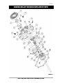
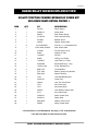
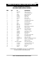
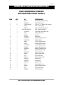
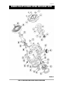
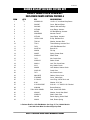
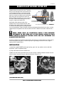
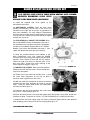
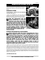
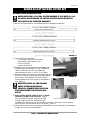
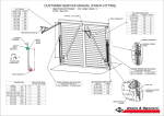
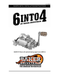
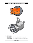
1
V4-101613
BAKER BILLET KICKER COVER KIT
P/N: 478-56MP-K
478-56HP-K
478-56CP-K
479-56P-K
(MECHANICAL BILLET KICKER COVER)
(HYDRAULIC BILLET KICKER COVER)
(CABLE STYLE BILLET KICKER COVER)
(FF HYDRAULIC BILLET KICKER COVER)
**FF stands for Function Formed**
PAGE 1- COVER
V4-101613
BAKER BILLET KICKER COVER KIT OVERVIEW
FEATURES
The new Premium BAKER Billet Kicker Covers is yet another part that we added to the ever
growing BAKER product line. These show polished gems are made out of Billet 6061-T6 for
added strength and increased part life. Stainless Steel T303 release shaft housing with O-Ring
(mechanical version only) keeping that fluid inside the transmission; no more leaking shafts, our
renowned strong and smooth BAKER Klassic Kicker Gears, and solid one piece kicker shaft for
those guys who just kick the shit out of their bike.
FITMENT
•
•
BAKER 6N4 Transmission
4-Speed 1936-1986 FL® / FX® Models
The BAKER Billet Mechanical Kicker Cover is the most historical; requires the use of a clutch
release arm, 1936-1986 Knucklehead / Panhead / Shovelhead Motors.
The BAKER Billet Hydraulic Kicker Cover is designed to work with an 11/16” Bore Diameter
Hydraulic Clutch Lever. This is the size of the Factory Clutch Lever, and the most common size of
aftermarket Clutch Levers.
The BAKER Billet Cable Type Kicker Cover is designed to work with O.E. type clutch cables from
1990-2006 and includes ball-ramp actuation components.
TOOLS, RESOURCES, REQUIRED PARTS
•
Factory Service Manual For Your Motorcycle
•
Factory Parts Manual For Your Motorcycle
•
Common Hand Tools (allens, sockets, hammer / chisel)
•
Torque Wrench (with ft. lbs. and in. lbs.)
•
Blue Loctite® (242 Removable) or Equivalent
•
Red Loctite® (271 Permanente) or Equivalent
•
Starter Clutch Puller (H-D® P/N 95650-42 or equivalent)
•
Transmission Fluid: BAKER Recommends: Spectro™ Heavy Duty Platinum 6 Speed
Transmission Oil, P/N R.HDPG6
THESE ADDITIONAL ITEMS ARE NEEDED FOR THE HYDRAULIC
KICKER COVERS PN: 478-56HP-K & PN: 479-56P-K
•
10MM Banjo Fittings
•
Hydraulic Line
•
Hydraulic Fluid: We Recommend H-D® DOT 5 Brake Fluid (P/N 99902-77)
•
Loctite® Thread Sealant (567); available at your local auto parts store
•
Hydraulic Master Cylinder with an 11/16” Bore
PAGE 2- OVERVIEW
V4-101613
BAKER BILLET KICKER COVER KIT
TABLE OF CONTENTS:
2) Overview
3) Table Of Contents
4) Included Parts Breakdown FF Hydraulic Cover
5) Included Parts Breakdown FF Hydraulic Cover Legend
6) Included Parts Breakdown Hydraulic Cover
7) Included Parts Breakdown Hydraulic Cover Legend
8) Included Parts Breakdown Mechanical Cover
9) Included Parts Breakdown Mechanical Cover Legend
10) Included Parts Breakdown Cable Style Cover
11) Included Parts Breakdown Cable Style Cover Legend
12) Cover Preparation
13) Cover Preparation Continued, Installation
14) Installation Continued
15) Installation Continued, Bleeding Hydraulic System
16) Bleeding Hydraulic System Continued, Finish Line
17) Release Rod for 1936-69 Models
18) Terms
19) Disclaimer
PAGE 3- TABLE OF CONTENTS
V4-101613
BAKER BILLET KICKER EXPLODED VIEW
FIGURE 1
PAGE 4- INCLUDED PARTS DETAIL FF HYDRAULIC COVER
V4-101613
BAKER BILLET KICKER EXPLODED VIEW
BILLET FUNCTION FORMED HYDRAULIC COVER KIT
INCLUDED PARTS DETAIL FIGURE 1
ITEM
QTY
PN
DESCRIPTION
1
1
291222
Return Spring
2
1
33096-54
Kicker Shaft
3
1
292013
Stud, Return Spring
4
2
51740-001
Zero Leak Drain Plug
5
1
45-9404
Bleeder Screw
6
1
292016
Washer, Kicker Shaft
7
9
8
1
9
1
479-56P
FF Hyd. Kicker Cover
10
1
66827
O-Ring, Fill Cap
11
1
130-56FP
Fill Plug
12
2
66855
O-Ring, Hyd. Piston
13
1
124-56LD
Hyd. Piston (1.5” DIA)
14
1
6391K269
Bronze Bushing, 2” Long
15
1
10705-01149
E-Clip, Release Rod
16
2
BD411-56
Thrust Washer
17
1
FNT-1024
Bearing, Heavy Duty Needle
18
1
BD410-56
Spacer, Bearing
19
*1*
7078
1970-E84 Release Rod
20
1
33350-56
Crank Gear
21
1
292014
Lock Tab, Crank Gear
22
1
7073
Nut, Crank Gear
23
1
7071
Nut, Starter Gear
24
1
290225
Lock Washer, Starter Gear
25
1
2213
Key, Starter Gear
26
1
33560-56
Starter Clutch Gear
27
1
33430-56
Starter Gear
28
1
6N4-SIDE
Gasket, Kicker Cover
29
1
290227
Spring, Starter Gear
31C125KCSS/P
.750X1.250X.250ADL
5/16-18 X 1 ¼” Polished SHCS
Seal, Kicker Shaft
* = Release Rod For 1970-E84 Models. See Page 17 For 1936-69 Models
Late 1984-Later Must Use Stock Style 3pc Rod
PAGE 5- INCLUDED PARTS DETAIL FF HYDRAULIC LEGEND
V4-101613
BAKER BILLET KICKER EXPLODED VIEW
INCLUDED PARTS DETAIL HYDRAULIC COVER
FIGURE 2
PAGE 6- INCLUDED PARTS DETAIL HYDRAULIC COVER
V4-101613
BAKER BILLET KICKER COVER EXPLODED VIEW
BILLET HYDRAULIC COVER KIT
INCLUDED PARTS DETAIL FIGURE 2
ITEM
QTY
PN
DESCRIPTION
1
1
6N4-SIDE
Gasket, Side Cover
2
*1*
7078
1970-E84 Release Rod
3
1
290227
Spring, Starter Gear
4
1
45-9404
Bleeder Screw
5
1
33430-56
Starter Gear
6
1
33560-56
Starter Clutch
7
1
2213
Key, Starter Clutch
8
1
290225
Lock Washer, Starter Clutch
9
1
7071
Nut, Starter Clutch
10
1
7073
Nut, Crank Gear
11
1
292014
Lock Tab, Crank Gear
12
2
BD411-56
Thrust Washer
13
1
FNT-1024
Bearing, Heavy Duty Needle
14
1
BD410-56
Spacer, Bearing
15
1
10705-01149
E-Clip, Release Rod
16
2
66855
O-Ring, Hyd. Piston
17
1
124-56LD
Hyd. Piston (1.5” DIA)
18
1
639K269
Bronze Bushing
19
1
33350-56
Crank Gear
20
1
291222
Return Spring, Kicker Shaft
21
1
292013
Stud, Return Spring
22
1
33096-54
Shaft, Crank Gear
23
9
31C125KCSS/P
5/16-18 x 1 ¼” SHCS S.S. Polished
24
1
292016
Washer, Crank Gear Shaft
25
9
6100
Washer, 5/16” AN
26
1
27
1
51740-001
Level Plug, 3/8-24 Zero Leak
28
1
478-56HP
Hydraulic Kicker Cover
29
1
2418T141
Buna #116
30
1
292032
Fill Cap
.750x1.250x.250ADL
Seal, Crank Gear Shaft
*= Release Rod For 1970-E84 Models. See Page 17 For 1936-69 Models
Late 1984-Later Must Use Stock Style 3pc Rod
PAGE 7- INCLUDED PARTS DETAIL HYDRAULIC LEGEND
V4-101613
BAKER BILLET KICKER COVER EXPLODED VIEW
INCLUDED PARTS DETAIL MECHANICAL COVER
FIGURE 3
PAGE 8- INCLUDED PARTS DETAIL MECHANICAL COVER
V4-101613
BAKER BILLET KICKER EXPLODED VIEW
BILLET MECHANICAL COVER KIT
INCLUDED PARTS DETAIL FIGURE 3
ITEM
QTY
PN
DESCRIPTION
1
1
291222
Return Spring, Kicker Shaft
2
1
33096-54
Shaft, Crank Gear
3
9
31C125KCSS/P
5/16-18 x 1 ¼” SHCS S.S. Polished
4
1
292013
Stud, Return Spring
5
1
292016
Washer, Crank Gear Shaft
6
1
.750x1.250x.250ADL
7
1
51740-001
Level Plug, 3/8-24 Zero Leak
8
9
6100
Washer, 5/16” AN
9
1
292032
Fill Cap
10
1
2418T141
Buna #116
11
1
478-56MP
Mechanical Kicker Cover
12
1
37074-38C
Release Shaft
13
1
66808
O-Ring, Release Shaft
14
1
476-56
Release Shaft Housing
15
1
37070-39B
Lever, Release Shaft
16
1
6443HW
Washer, Release Shaft
17
1
6391K183
Bushing, Release Shaft
18
1
68077
E-Clip, Release Shaft
19
1
6N4-SIDE
Gasket, Side Cover
20
1
290227
Spring, Starter Gear
21
1
7073
Nut, Crank Gear
22
1
292014
Washer, Crank Gear
23
1
33430-56
Starter Gear
24
1
33350-56
Crank Gear
25
1
33560-56
Starter Clutch
26
1
2213
Key, Starter Clutch
27
1
290225
Washer, Starter Clutch
28
1
7071
Nut, Starter Clutch
29
1
639K269
Bronze Bushing
Seal, Crank Gear Shaft
PAGE 9- INCLUDED PARTS DETAIL MECHANICAL LEGEND
V4-101613
BAKER BILLET KICKER COVER EXPLODED VIEW
FIGURE 4
PAGE 10- INCLUDED PARTS DETAIL CABLE STYLE COVER
V4-101613
BAKER BILLET KICKER COVER KIT
BILLET CABLE STYLE COVER KIT
INCLUDED PARTS DETAIL FIGURE 4
ITEM
QTY
PN
DESCRIPTION
1
6
25C50KLHS
1/4-20 x ½” Low Head Cap Screw
2
1
584-56P
Cover, Ball and Ramp
3
1
583-GAS
Gasket, Ball and Ramp
4
1
WT3096
Inner Ramp, Actuator
5
3
987687
3/8” Ball Bearing, Actuator
6
1
3094-DSSC
Actuator Ferrule
7
1
WT3196
Outer Ramp, Actuator
8
1
10705-01149
E-Clip, Release Rod
9
2
TWC411
Washer, Actuator Rod
10
1
TC411
Thrust Bearing, Actuator Rod
11
*1*
7078
1970-E84 Release Rod
12
1
2418T141
Buna #116
13
1
292032
Fill Cap
14
1
290227
Spring, Starter Gear
15
1
33430-56
Starter Gear
16
1
7073
Nut, Crank Gear
17
1
33560-56
Starter Clutch
18
1
292014
Lock Tab, Crank Gear
19
1
2213
Key, Starter Clutch
20
1
290225
Lock Washer, Starter Clutch
21
1
33350-56
Crank Gear
22
1
7071
Nut, Starter Clutch
23
1
6N4-SIDE
Gasket, Kicker Cover
24
1
578-56MP
Cover, Cable Style
25
1
51740-001
Level Plug, 3/8-24 Zero Leak
26
9
6100
Washer, 5/16” AN
27
9
31C125KCSS/P
5/16-18 x 1 ¼” SHCS S.S. Polished
28
1
639K269
Bronze Bushing
29
1
.750x1.250x.250ADL
30
2
AS2035
Washer, Crank Gear Shaft
31
1
33096-54
Shaft, Crank Gear
32
1
291222
Return Spring, Kicker Shaft
33
1
292013
Stud, Return Spring
Seal, Crank Gear Shaft
*= Release Rod For 1970-E84 Models. See Page 17 For 1936-69 Models
Late 1984-Later Must Use Stock Style 3pc Rod
PAGE 11- INCLUDED PARTS DETAIL HYDRAULIC LEGEND
V4-101613
BAKER BILLET KICKER COVER KIT
DISSASSEMBLY
1) FOR YOUR SAFETY, DISCONNECT BOTH BATTERY CABLES (FAILURE TO DUE SO
COULD RESULT IN PERSONAL INJURY).
2) With your bike securely supported on a bike lift or jack, drain the transmission fluid. Refer to
your Factory Service Manual for location of your drain plug.
3) Depending on the style of exhaust that you have on your motorcycle, the exhaust may need to
be removed at this time as well to allow access to the transmission side cover. Remove the stock
side cover, as well as the factory clutch actuator rod and set aside.
3a) FOR HYDRAULIC COVERS: While referencing the Factory Service manual, remove the
clutch cable, cable style clutch lever and set aside.
4) Remove the derby cover and back off the jam nut for the clutch adjustment.
5) Remove the starter clutch, gear and spring following the procedures listed in your Factory
Service Manual. Starter Clutch Puller: H-D® P/N 95650-42 or equivalent is necessary for
removal.
6) Take the time to wipe down the gasket surface of the bearing door and inspect to make sure it
is free of residual oil, old gasket material and debris.
THE REMOVAL OF THE OIL DEFLECTOR ON EARLY STYLE 4-SPEED
TRANSMISSIONS IN NECESSARY FOR PROPER FITMENT OF THE
HYDRAULIC KICKER COVER. IF REMOVING THE STUDS TO USE THE
BOLTS SUPPLIED; CHASE THREADS WITH A 5/16-18 TAP USING CAUTION NOT
TO DAMAGE THE THREADS IN YOUR CASE.
KICKER COVER PREPERATION
USE CAUTION WHEN ASSEMBLING SO THAT YOU DO NOT
DAMAGE THE COVER AND OR ITS COMPONENTS.
1) Referring to the exploded view (Figure 1, 2, 3 or 4) apply a
little lube in the side cover within the kicker shaft bore and on
the shaft seal.
2) Install the kicker shaft washer onto the kicker shaft with the
inside of the washer chamfer facing toward the threaded end
of the shaft. (Figure 5)
3) Apply some transmission oil on the kicker shaft and install it
through the side cover.
FIGURE 5
NOTE CHAMFER FACING THREADED END
ALIGNMENT OF SHAFT TO CRANK GEAR IS NESSESSARY FOR PROPER
OPERATION. SEE FIGURE 6. FAILURE TO DUE SO COULD RESULT IN
DAMAGE TO COVER ASSEMBLY, KICKER GEARS, AND OR PERSONAL
INJURY. THE BOTTOM DASHED LINE IS FOR THE CABLE STYLE COVER (47856CP-K) ALIGNMENT ONLY.
4) Install the BAKER crank gear onto the shaft with supplied crank gear washer and crank gear
nut using “BLUE” thread lock. Torque to 30 ft lbs.
5) Bend over the lock tabs on the crank gear washer to secure the crank gear nut.
(CONTINUED ON NEXT PAGE)
PAGE 12- COVER PREP
V4-101613
BAKER BILLET KICKER COVER KIT
6a) FOR HYDRAULIC COVERS: Remove the
hydraulic piston from the side cover. The best
way is to use the light touch of an air blow gun
in the hydraulic feed port. It should be noted
that you should have the side cover back side
down on a couple of towels on the work bench
when doing this as the piston will shoot out.
When you have the piston out, give it a bath of
H-D DOT 5 Brake Fluid making sure to fully
coat the o-rings in the brake fluid.
BOTTOM IS FOR CABLE
STYLE CO VERS ONLY
6b) Double check that the inside of the
hydraulic bore is free of debris and dirt. Also
ALIGN GEAR BOSS WITH KEYWAY IN SHAFT FIGURE 6
check the entire inside surface of the side cover
to eliminate introducing dirt or packing material
into your transmission. With the inside of the part checked and determined to be clean, coat the
inside walls of the hydraulic bore with the same H-D DOT 5 Brake Fluid used to lubricate the orings.
THESE EXTRA STEPS OF LUBRICATION MAKE A VERY DRAMATIC
DIFFERENCE IN THE WEAR LIFE OF THE SEALING O-RINGS IN YOUR
BAKER PREMIUM HYDRAULIC KICKER COVER AND ARE NECESSARY FOR
CORRECT PART FUNCTION.
6c) Using a gentle touch, slide the piston back in the side cover until it bottoms out. Take care to
not force the piston into place; in such a way that o-ring damage could occur on the edge or
opening of the Hydraulic Bore.
INSTALLATION
1) Install the supplied BAKER ratchet gear spring, gear, hub, key, washer, and nut with blue
thread lock. (refer to exploded views)
2) Torque the ratchet hub nut to 50-60 ft lbs.
3) Make sure the ratchet gear slides freely in and out with no binding. Bend the washer over the
nut so it locks it into place using a mallet and chisel tip. (Figure 7, 8)
FIGURE 7
FIGURE 8
BENDING TAB OVER
(CONTINUED ON NEXT PAGE)
PAGE 13-COVER PREP, INSTRUCTIONS
SHOWN WITH TAB BENT OVER
V4-101613
BAKER BILLET KICKER COVER KIT
IT IS CRITICAL THAT CARE IS TAKEN WHEN BENDING OVER WASHER;
EXCESSIVE HAMMERING COULD CAUSE
DAMAGE TO THE MAIN SHAFT OR BEARINGS
4) Install the supplied side cover gasket on the
transmission at this time.
4a) MECHANICAL COVERS: Place the stock clutch
actuator rod assembly into the hole in the end of the
mainshaft on the right side of the bike in preparation for
side cover installation. For early 4-Speed Transmissions
with large clutch release bearing; install bearing into kicker
cover at this time, making sure that the bearing is aligned
with the fork. (Figure 9)
INSTALLING EARLY THROWOUT BEARING
FIGURE 9
4b) FOR HYDRAULIC / CABLE TYPE COVERS: Place
the provide BAKER release rod assembly in the end of
the mainshaft on the right side of the bike in preparation
for side cover installation. Release Rod is for 1970-E84
Models; if you have a 1936-69 Model, see page 17. Late
1984-Later Models use stock style 3pc rod setup.
5) Using the provided fasteners and washers or the
stock transmission cover nuts. Install the BAKER
Premium Kicker Cover using care aligning the gear teeth
together. Cover should fit flush with out any tension.
Torque the side cover down to 190-220 in-lbs (17-23
Nm) using ‘Blue’ Thread Lock while referring to the
torque sequence diagram. (Figure 10)
TORQUE SEQUENCE
FIGURE 10
6) CABLE STYLE COVERS: Remove the six fasteners
holding on the ball and ramp cover; remove the ball and
ramp cover and gasket.
6a) Thread your clutch cable into the side cover. Loosen
the clutch cable adjustment all the way so there is
maximum cable exposed in the side cover.
6b) With the cable fully extended in the side cover take the
supplied ball and ramp assembly and slide it over the
cable. Install the clutch cable ferrule (PN 3094-DSSC)
and ‘seat’ the cable; figure 11
6c) Install the ball and ramp assembly with outer ramps
‘tab’ in the 2 ‘o’clock position; figure 12
INSTALLING FERRULE ON CABLE
FIGURE 11
6d) Place the ball and ramp cover plate with gasket back into position. Using ‘Blue’ thread lock,
install the six bolts. Torque the six 1/4-20 x 1/2” (PN 25C50KLHS) to 7-9 ft/lbs (84-108 in/lbs).
7) Install the kick arm return spring using care turning it clockwise (spring will be under pressure
when installing) until it’s locked onto the return spring stud; figure 13
(CONTINUED ON NEXT PAGE)
PAGE 14- INSTALLATION
V4-101613
BAKER BILLET KICKER COVER KIT
8) MECHANICAL COVERS: Install your factory stock
release arm and kick arm / pedal following your Factory
Service Manual. Adjust your clutch per Factory Service
Manual.
HYDRAULIC COVERS
FOR MECHANICAL / CABLE STYLE COVER PROCEED
TO FINISH LINE PAGE 16
1) Bolt to the handlebars the 11/16” bore clutch lever
assembly of your choice. Run the AN -3 brake line down to
the side cover and bolt it in place with a 3/8”-24 Thread
Banjo Bolt. Torque Banjo Bolt to 17-22 ft-lbs. (23-30 Nm).
TAB SHOWN IN 2’O’CLOCK POSITION
FIGURE 12
TAKE THE NENECESSARY TIME AND
PROPER PRECAUTIONS TO ROUTE THE
HYDRAULIC LINE AWAY FROM MOVING
PARTS AND ANY EXHAUST PIPES THAT COULD
DAMAGE THE LINE IN ANY WAY. MAKE SURE
THAT YOU ARE ABLE MOVE THE FRONT END
THROUGH ITS FULL RANGE OF MOTION LEFT
TO RIGHT WITHOUT BINDING, KINKING OR
PINCHING THE HYDRAULIC LINE. FAILURE TO
DO SO COULD RESULT IN PARTFAILURE OR
SHOWN W/ SPRING AND RELEASE ARM FIGURE 13
PERSONAL INJURY.
BLEEDING THE HYDRAULIC CLUTCH SYSTEM
BAKER DRIVETRAIN MAKES THE STRONG RECOMMENDATION THAT A
POWER BLEEDER SYSTEM BE UTILIZED, WHETHER THAT IS A HAND
OPERATED PUMP OR PNEUMATIC, TO BLEED THE HYDRAULIC CLUTCH
SYSTEM ON YOUR MOTORCYCLE. IT IS THE MOST EFFECTIVE AND ONLY
SUREFIRE WAY TO ENSURE THAT ALL OF THE AIR BUBBLES ARE PURGED
FROM THE SYSTEM. IF YOU DO NOT OWN A POWER BLEEDER, THE
FOLLOWING SET OF INSTRUCTIONS WILL ENABLE YOU TO BLEED YOUR
CLUTCH SYSTEM. GREAT CARE AND ATTENTIONS NEEDS TO USED IN
FOLLOWING THESE STEPS TO ENSURE A PROPERLY BLED AND FUCNTIONING
SYSTEM TO ENSURE YOUR SAFETY AS A RIDER.
1) Before you can bleed the Hydraulic Clutch system you need to adjust the free play and rod
length at the clutch. Using an Allen wrench, run the adjuster bolt (center of the clutch) inboard
until it can be felt to bottom the piston out in the side cover. You will also know that you have hit
the bottom point as the clutch will begin the move. At the point where it is fully bottomed out, back
the adjuster off ½ to 1 full turn. The closer to the 1 full turn point that you adjust it too, the more
reserve you will have in the lever before the motorcycle begins to move, with the full engagement
of the clutch being proportionally closer to the end of the sweep of the lever. This amount can be
adjusted to rider comfort and riding style. Tighten the jam nut to 120 in-lbs while holding the
adjuster screw from rotating.
(CONTINUED ON NEXT PAGE)
PAGE 15- INSTALLATION, BLEEDING OF THE HYDRAULIC SYSTEM
V4-101613
BAKER BILLET KICKER COVER KIT
2) Place a clear tube over the bleeder valve on the side cover and run it into a clean container.
3) Stand the motorcycle upright so that the master cylinder on the clutch lever is level. Remove
the master cylinder lid and gasket.
4) Add new DOT 5 Silicone Brake Fluid to the master cylinder reservoir under to the fluid level is
at or below the full line. DO NOT OVERFILL THE MASTER CYLINDER
5) Squeeze the lever 5-10 times. Open the bleeder valve on the side cover and clutch fluid should
flow through the tubing. If not, keep pumping the lever as it may take a few minutes for the fluid to
make it all of the way through the line and cover. Once fluid begins to flow through the clear tube,
close the bleeder valve. It may be necessary to add more fluid during this time even before any
fluid begins to flow out of the clear tubing.
6) Squeeze the clutch lever and hold it against the handlebar to build up hydraulic pressure.
Open the bleeder valve on the side cover about ½ turn. Clutch fluid will flow through the clear
tubing. Close the bleeder when the clutch lever has traveled about 50-75% of its full travel. Wait
for the clutch lever to return to its released position. Repeat step 6 as necessary until all air
bubbles have been forced out of the system and there is no bubbles in the fluid within the clear
tubing.
7) When the system has been fully bled and the clutch lever no longer feels mushy, fully tighten
the bleeder valve on the side cover to 80 in-lbs. It may be necessary to fill the fluid in the reservoir
to the full line at this time. DO NOT OVERFILL THE MASTER CYLINDER.
8) Place the cover back on the master cylinder and tighten down according to the control
manufacturer’s specifications. Check to make sure that the clutch line is tight at the clutch lever
and the side cover at this time.
9) Replace the derby cover on the primary, referring to the Factory Service Manual for the proper
tightening sequence.
FINISH LINE
1) Remove the fluid level plug on your new kicker cover. Remove your fill plug; fill your
transmission until the fluid starts to weep out the level hole. Fluid capacity is about 20-24fl oz:
BAKER Recommends: Spectro™ Heavy Duty Platinum 6 Speed
Transmission Oil, P/N
R.HDPG6.
2) Re-install your fill plug and level plugs. Re-install the exhaust if removed and double check that
all fasteners are tight on the motorcycle, any ancillary parts that you removed to perform this
installation are back in their intended place on the motorcycle.
Once the maiden voyage had been made around
the block or down the road. Take the time to
double check all fasteners and hydraulic fittings for
tightness. Also with the bike as close to level as
you can safely get it and the transmission fluid
warmed up, double check the level of the fluid
using a 3/16” Allen to remove the oil level plug.
Drain off any excess fluid if the transmission is
overly full. Level should be at the bottom of the
hole. Re-install the oil level plug with; snug. You
are complete…
SHOWN INSTALLED WITH KICK ARM AND PEDAL
PAGE 16- BLEEDING THE HYDRAULIC SYSTEM, FINISH LINE
FIGURE 14
V4-101613
BAKER BILLET KICKER COVER KIT
RELEASE ROD MODIFICATION
BAKER SUPPLIES A 1970-E84 CLUTCH RELEASE; IF YOU HAVE A 193669 MODEL MODIFICATION TO THE ROD LENGTH IS NECESSARY FOR
YOUR CLUTCH TO FUNCTION PROPERLY.
1) Refer to the figure below for your desired release rod length per model year.
14.125” (358.77MM) OVERALL
BAKER SUPPLIED RELEASE ROD
13.810” (350.77MM) OVERALL
MODIFIED RELEASE ROD FOR 1965-69
13.550” (344.17MM) OVERALL
MODIFIED RELEASE ROD FOR 1936-64
FIGURE 15
2) Tools required to modify parts
• Cut off wheel, chop box or equivalent
• Belt sander, bench grinder, or file
• Torch or map gas
• Small container of oil
3) Using figure 15 cut the supplied rod to desired length;
example 1965-69 models cut off 0.315” (8.00MM) or
1936-64 models cut off 0.575” (14.60MM). All
measurements are within +/- 0.010” (+/- 0.25MM).
4) After the release rod has been cut to desired length, put
a chamfer on the end to break the sharp edge, this will
also to ease in the installation of the rod. Chamfer
could be added using a bench grinder / belt sander or
a file. Figure 16
CHAMFER ADDED TO ROD
FIGURE 16
HARDEN THE END OF THE RELEASE
SHAFT AFTER MODIFICATION
THIS WILL STRENGTHEN THE END SO
THAT PREMATURE FAILURE DOES NOT
OCCUR.
5) USE CAUTION AND BE CAREFUL NOT TO BURN
YOURSELF DURING THIS PROCESS. Using a
TORCH AND IMMERSE ROD IN OIL FIGURE 17
torch or preferably map gas, heat the end of the
rod until it starts to glow red; heat about 1.000”
(25.4MM) of the rod end making sure to heat the rod evenly. Once the rod is red (cherry)
quickly quench / immerse the hot end in an oil bath. Figure 17
6) Let the rod cool then clean the end using a Scotch-Brite™ pad or sand paper. Proceed back
to page 14 for the rest of the installation.
PAGE 17- RELEASE ROD MODIFICATION
V4-101613
BAKER BILLET KICKER COVER KIT
SPECIALORDERS
A minimum $500 deposit is required with all special orders. Special orders include unique case finishes, unique side door
requests (i.e.; wrinkle black door or no logo).
ALL OTHER ORDERS
Orders can be pre-paid using VISA, MasterCard or American Express.
Prices shown are F.O.B. Haslett, MI. BAKER™ provides free UPS ground shipping on all retail orders for complete
transmissions or transmission kit. UPS air shipment is available upon request. Customer is responsible for air shipment
premiums.
LIMITED WARRANTY
BAKER™ Inc. transmission assemblies, transmission kits, and wide tire kits are guaranteed to the original purchaser to be
free of manufacturing defects in materials and workmanship for a period of 2 years from the date of purchase or up to
24,000 miles - whichever is sooner.
If the product is found by BAKER™ to be defective, such products will, at the option of BAKER™, be replaced or repaired
at cost to BAKER™.
In the event warranty service is required, the original purchaser must call or write BAKER™ immediately with the problem.
If it is deemed necessary for BAKER™ to make an evaluation to determine whether the transmission assembly or
transmission kit is defective, the entire transmission assembly, whether originally purchased as an assembly or kit, must
be properly packaged and returned prepaid to BAKER™ with a copy of the original invoice of purchase.
If after an evaluation has been made by BAKER™ and a defect in materials and/or workmanship is found, BAKER™ will,
at BAKER™ option, repair or replace the defective part of the assembly.
Warranty card must be returned within 45 days of purchase to be valid.
ADDITIONALWARRANTY PROVISIONS
This limited warranty does not cover labor or other costs or expenses incidental to the repair and or replacement of
BAKER™ products. This warranty does not apply if one or more of the following situations is judged by BAKER™ to be
relevant: improper installation, accident, modification (including but not limited to use of unauthorized parts), racing, high
performance application, mishandling, misapplication, neglect (including but not limited to improper maintenance), or
improper repair.
BAKER™ shall not be liable for any consequential or incidental damages arising out of or in connection with a BAKER™
transmission assembly, transmission kit, swingarm, fender, component or part. Consequential damages shall include
without limitation, loss of use, income or profit, or losses sustained as the result of injury (including death) to any person or
loss of or damage to property.
BAKER™ transmissions, transmission kits, and Wide Tire Kits are designed exclusively for use in Harley-Davidson®
motorcycles. BAKER™ shall have no warranty or liability obligation if a BAKER™ part is used in any other application.
If it is determined that a BAKER™ transmission assembly has been disassembled during the warranty period for any
reason, this limited warranty will no longer apply.
PAGE 18- TERMS
V4-101613
BAKER BILLET KICKER COVER KIT
The words Harley and H-D are registered trademarks and are for reference only. Use of H-D model designations and part
numbers are for reference only. BAKER Drivetrain has no association with, and makes no claim against, these words,
trademarks, or companies.
It is the sole responsibility of the user to determine the suitability of this product for his or her use, and the user shall
assume all legal, personal injury risk and liability and all other as well as all other obligations, duties and risks associated
therewith.
CUSTOMER SUPPORT
For any installation or service questions, please contact our BAKER technical department toll free: 1-877-640-2004.
PAGE 19- DISCLAIMER