1
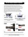
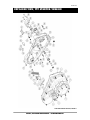
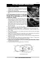
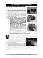
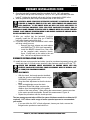
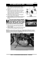
V5-051413
BAKER
CRUISE
DRIVEPRIMARY
TOP COVER
BAKER
TIN TYPE
PAGE 1 | COVER
V5-051413
TIN TYPE PRIMARY OVERVIEW
FEATURES
•
•
•
•
•
•
•
•
•
•
Billet 6061-T6 aluminum inner and outer primary housings available in steel shot
blasted or show polished finish
Available in kick only and 1.4kw 1990-2006 style starter configuration
Starter type includes jackshaft and related hardware
Modern chain fine tooth adjuster shoe and L-bracket included
O-ring sealed locking flanged nuts for transmission-to-inner primary studs
Nostalgic slotted screws, gasket, and related hardware included
Zero Leak drain plug with magnet standard
Chain oiler and suction hardware included
Inner primary is reinforced for strength around the mainshaft bore
Works with stock style derby and inspection covers
OPTIONAL RELATED HARDWARE
•
•
•
Aluminum Derby and Inspection cover kit, pn3102-TTP-P Show Polished and
pn3102-TTP-R Shot Blasted
Splined 4-Speed mainshaft and Splined Shovel Clutch (diaphragm type),
recommended for 93+” motors, pn9P401
Clutch release arm kit, pnTTP-200A (use with stock style mechanical cable)
FITMENT
•
•
•
•
1970-E84 Shovelhead® 4 Speeds
BAKER 6N4
Custom Applications (Alternator/Stator Motors)
Not Compatible With Factory Mid Controls
TOOLS, RESOURCES, REQUIRED PARTS
•
•
•
•
•
•
•
•
•
•
•
•
•
•
•
Factory Service Manual For Your Motorcycle
Factory Parts Manual For Your Motorcycle
Common Hand Tools (Allen Wrenches, Sockets, Screwdrivers etc.)
½” Impact Gun, 1 1/2” Socket (Motor), 1 7/16” and 1 3/16” Socket (Clutch)
Torque Wrench (ft-lbs. and in-lbs.)
Clutch Hub Puller, pn 95960-41A or Equivalent
Dial Calipers or Equivalent (Chain Alignment)
Straight Edge (Chain Alignment)
Blue Loctite® (242 Removable) or Equivalent
Red Loctite® (271 Permanent) or Equivalent
Permatex® Silicone Sealant or Equivalent
Pipe Thread Sealant (Loctite® 567) or Equivalent
Motor O-Ring (pn11147A)
Motor Sprocket Kit with Shims (1955-64 Splined Non-Compensator)
1990-2006 1.4kw H-D® Starter pn 31553-94B (Starter Versions Only); With New
Cable & Boot
PAGE 2|OVERVIEW
V5-051413
TIN TYPE PRIMARY
TABLE OF CONTENTS:
2.
Overview
3.
Table Of Contents
4.
.983” VS 1.000” Mainshaft Diameters (For Old Style 6N4 Users)
5.
Included Parts Breakdown Tin Type Primary, Starter Version
6.
Included Parts Breakdown Tin Type Primary, Starter Version Legend
7.
Included Parts Breakdown Tin Type Primary, Kicker Version
8.
Included Parts Breakdown Tin Type Primary, Kicker Version Legend
9.
Preparation Tin Type Primary
10. Tin Type Primary Installation
11. Tin Type Primary Installation Starter Versions
12. Tin Type Primary Installation Starter Versions / Continued
13. Tin Type Primary Installation Continued
14. Tin Type Primary Installation Continued / Finish Line
15. Terms
16. Disclaimer
PAGE 3|TABLE OF CONTENTS
V5-051413
TIN TYPE PRIMARY MAINSHAFT DIAMETERS
TTP PART NUMBER AND FITMENT FOR MAINSHAFT DIAMETERS
TTP Part Numbers for the old style 6N4 with the .983” diameter mainshaft:
PN 3100-TTP-R-6N4, Media blasted TTP assembly w/ hardware, Kick Only -6N4 w/ .983” Shaft
PN 3100-TTP-P-6N4, Show polished TTP assembly w/ hardware, Kick Only -6N4 w/ .983” Shaft
PN 3101-TTPS-R-6N4, Media blasted TTP assembly w/ hardware, Starter Version -6N4 w/ .983” Shaft
PN 3101-TTPS-P-6N4, Show polished TTP assembly w/ hardware, Starter Version -6N4 w/ .983” Shaft
TTP Part Numbers for the BAKER 4-Speed & 6N4 with the 1.000” diameter mainshaft:
PN 3100-TTP-R, Media blasted TTP assembly w/ hardware, Kick Only, 4-Speed & 6N4
PN 3100-TTP-P, Show polished TTP assembly w/ hardware, Kick Only 4-Speed & 6N4
PN 3101-TTPS-R, Media blasted TTP assembly w/ hardware, Starter Version 4-Speed & 6N4
PN 3101-TTPS-P, Show polished TTP assembly w/ hardware, Starter Version 4-Speed & 6N4
TTP bearing & seal placement for the current, 1.000” diameter and .983” diameter
mainshafts:
4-SPEED AND NEW STYLE 6N4 W/ 1.000” MAINSHAFT
R16DDUCE BEARING, 200 RRRI SNAP RING AND
56-5101 SEAL
OLD 6N4 W/ .983” MAINSHAFT
16005 BEARING, 56-1068A ADAPTER SLEEVE, NO
SNAP RING AND 56-5101 SEAL
Old .983” & Current 1.000” diameter mainshaft images:
Note:
We had a couple part numbers for the stepped .983″ mainshaft; PN 996040-8 & PN 6N4-70xxxx.
(xxxx= month / year). The last stepped .983″ mainshaft were made in 2008 (PN 6N4-70xx08).
PAGE 4|.983” VS 1.000” MAINSHAFT DIAMETERS
V5-051413
EXPLODED VIEW, TTP STARTER VERSION
STARTER VERSION SHOWN; FIGURE 1
PAGE 5|INCLUDED PARTS DETAIL – STARTER VERSION
V5-051413
LEGEND, TTP STARTER VERSION
ITEM
QTY
1
2
3
4
5
6
7
8
9
10
11
12
13
14
15
16
17
18
19
20
21
22
23
24
25
26
27
28
29
30
31
32
33
34
35
36
36
37
38
39
40
41
42
43
44
45
46
47
48
49
50
$
$
10
$
$
10
1
1
1
1
1
1
1
2
1
1
2
1
2
2
2
1
1
1
1
1
1
1
1
4
1
4
1
2
2
*
*
1
1
1
1
1
1
1
1
1
2
2
2
1
3
PN
60645-GAS
60572-36
91790A539
60555-36
60640-GAS
91790A542
60510-S36
60635S-GAS
5304-37PP
39976-01
3068-DSSC
37024
33082
31C75KFC
3069-DSSC
21818
31C100KCSS/P
91030A455
26751
ZPN292216
13056
5346K15
99-1058
54446-004
732407-E
25C50HFB8Z
.203x.546x.048N
10F50KCS
37KKPFS
37FNGFOC
22H-S05M-CLR
2418T135
60625-S36
31588
63533-41A
R16DDUCE
16005 / 56-1068A
200RRRI
56-5101
37R75PDO
PAP2525P10
25R100PDP
12035B
TTP-125
60630-S36
31R100PDOS
31C175KCSS/P
31C125KCSS/P
6100
9213K17
9213K14
DESCRIPTION
Gasket, Inspection Cover
Inspection Cover
1/4-20 X .625” Oval Screw S.S.
Derby Cover
Gasket, Derby Cover
1/4-20 X 1.000” Oval Screw S.S.
Outer Primary
Gasket, Primary
E-Clip, 3/8”
Shoe, Tensioner
Tensioner L-Bracket
3/8-16 Nylock Nut
Washer, 3/8”
5/16-18 X .750 FHCS Black
Tensioner Plate
3/8-16 X 1.250” Bolt
5/16-18 X 1.000” SHCS S.S.
Flanged Motor Nut
1/4" X .750” Solid Dowel
Lock Tab
5/16-18 X 1.125” Hex Bolt
1/8” NPT Barb Fitting
Splined Washer, Starter Jackshaft
Spring, Starter Jackshaft
9 Tooth Starter Jackshaft
1/4-20 X .500” Hex Bolt W/Flange
Washer, Starter Bolt
10-32 X .500” SHCS Black
3/8-18 Socket Pipe Plug
3/8-24 Locking Flanged Nut
1/2-20 Hex Zero Leak with Magnet
O-Ring, Buna -110
Inner Primary
1/8” NPT Plug
1/8” NPT Nipple
Bearing, Inner Primary
Bearing & Adapter, Primary (Old 6N4 Only)
2” Internal Snap Ring
Seal, Inner Primary
3/8” X .750” Solid Dowel
Permaglide Bearing
1/4" X 1.000” Dowel
Oil Seal, Starter Jackshaft
Collar, Starter Jackshaft
Starter Ear Standoff
5/16” X 1.000” Solid Dowel
5/16-18 X 1.750” SHCS S.S.
5/16-18 X 1.250” SHCS S.S.
5/16” Washer
1/4-20, 1” H, 1” W – Dampener
1/4-20, ½” H, 1” W – Dampener
Note: Add a “P” and the end of the part number for polished parts or an “R” at the end for raw blasted parts. Example:
60630-S36P (polished starter ear standoff). Item # 37 does not come in the kit if you are using with an old style 6N4
transmission with a .983” stepped mainshaft.
* = Customer preference; if you are using on a 4-Speed, 6N4 Transmission or old style 6N4 with .983” mainshaft.
$ = The Derby and Inspection Cover kit is sold separately (pn 3102-TTP-P / 3102-TTP-R).
PAGE 6 |INCLUDED PARTS DETAIL LEGEND – STARTER VERSION
V5-051413
EXPLODED VIEW, TTP KICK VERSION
KICKER VERSION SHOWN; FIGURE 2
PAGE 7 | INCLUDED PARTS DETAIL – KICKER VERSION
V5-051413
LEGEND, TTP KICK VERSION
ITEM
1
2
3
4
5
6
7
8
9
10
11
12
13
14
15
16
17
18
19
20
21
22
23
24
25
26
27
28
29
29
30
31
QTY
$
$
10
$
$
10
1
1
1
1
1
1
1
2
1
1
2
1
2
2
2
1
4
4
1
1
2
2
*
*
1
1
PN
60645-GAS
60572-36
91790A539
60555-36
60640-GAS
91790A542
60505-K36
60650K-GAS
5304-37PP
39976-01
3068-DSSC
37024
33082
31C75KFC
3069-DSSC
21818
31C100KCSS/P
91030A455
26751
13056
ZPN292216
5346K15
37FNGFOC
2418T135
22H-S05M-CLR
60620-K36
31588
63533-41A
R16DDUCE
16005 / 56-1068A
200RRRI
56-5101
DESCRIPTION
Gasket, Inspection Cover
Inspection Cover
1/4-20 X .625” Oval Screw S.S.
Derby Cover
Gasket, Derby Cover
1/4-20 X 1.000” Oval Screw S.S.
Outer Primary
Gasket, Primary
E-Clip, 3/8”
Shoe, Tensioner
Tensioner L-Bracket
3/8-16 Nylock Nut
Washer, 3/8”
5/16-18 X .750 FHCS Black
Tensioner Plate
3/8-16 X 1.250” Bolt
5/16-18 X 1.000” SHCS S.S.
Flanged Motor Nut
1/4" X .750” Solid Dowel
5/16-18 X 1.125” Hex Bolt
Lock Tab
1/8” NPT Barb Fitting
3/8-24 Locking Flanged Nut
O-Ring, Buna -110
1/2-20 Hex Zero Leak with Magnet
Inner Primary
1/8” NPT Plug
1/8” NPT Nipple
Bearing, Inner Primary
Bearing & Adapter, Primary (Old 6N4 Only)
2” Internal Snap Ring
Seal, Inner Primary
Note: Add a “P” and the end of the part number for polished parts or an “R” at the
end for raw blasted parts. Example: 60630-S36P (polished starter ear standoff).
Item # 30 does not come in the kit if you are using with an old style 6N4
transmission with a .983” stepped mainshaft.
* = Customer preference; if you are using on a 4-Speed, 6N4 Transmission or old
style 6N4 with .983” mainshaft.
$ = The Derby and Inspection Cover kit is sold separately (pn 3102-TTP-P /
3102-TTP-R)
PAGE 8 |INCLUDED PARTS DETAIL LEGEND – KICKER VERSION
V5-051413
TIN TYPE PRIMARY PREPARATION
DISSASSEMBLY:
1. Starting with the basics and for your safety,
2.
3.
4.
5.
6.
DISCONNECT BOTH BATTERY
TERMINALS (FAILURE TO DUE SO COULD
RESULT IN PERSONAL INJURY). Always
disconnect the negative terminal first.
Remove the battery, battery tray and then
drain your primary and oil tank. On some
models it is necessary to remove foot pegs /
floor boards in order to remove the outer
primary.
Remove your stock outer primary cover; refer
to your Factory Service Manual to remove your
stock clutch assembly and related primary
components
using
the
proper
safety
precautions and tools. Clutch hub puller tool
pn 95960-41A is used to remove the clutch
hub off of the transmission shaft, figure 3
Remove the oil tank, starter and inner primary
following your Factory Service Manual.
Loosen your transmission mounting plate nuts.
With all these components removed your bike
should like figure 4.
REMOVING CLUTCH HUB ASSEMBLY | FIGURE 3
STRIPED DOWN | FIGURE 4
TIN TYPE PRIMARY PREP:
BAKER DRIVETRAIN SHIPS THE TTP READY TO INSTALL WITH THE OIL DRIP
AND RETURN LINE FITTINGS. RUN THE TTP LIKE A MODERN WET PRIMARY
FOLLOW STEPS 3 - 6.
1. The TTP “Tin Type Primary” is shipped assembled; if you purchased the cover kit,
remove the derby, inspection covers and then outer primary cover with gaskets.
2. The inner primary has the mainshaft bearing, seal and chain tensioner assembly
installed, if you have a starter version TTP the starter ear standoff, permaglide, seal
and collar are installed and ready for installation; no disassembly of these items are
necessary.
Steps 3 – 6 are for running the primary like a
sealed modern wet setup
3. Remove the 1/8” NPT line fittings from the back
of the inner primary. For your reference refer to
Figure 1 or 2.
4. Install the two 1/8” NPT plugs (pn 31588) using
pipe thread sealant; snug both plugs. Figure 5
1/8” NPT PLUGS INSTALLED | FIGURE 5
shows the primary with plugs installed.
5. Remove the 1/8” NPT barb fitting (pn 5346K15) on
the inside, inner primary, for your reference refer to Figure 1 or 2.
6. The primary will vent through the transmission like a stock 5-speed setup. If you
have a clutch nut with a seal installed, the seal must be removed also a flat (length
wise) on the release rod added (like a 5-speed clutch release rod). This will ensure
proper venting of the primary by letting air to pass through the mainshaft.
PAGE 9 |PREPARATION TIN TYPE PRIMARY
V5-051413
TIN TYPE PRIMARY INSTALLATION
PRIMARY INSTALLATION:
1. Clean the motor O-Ring area making sure it is free
of debris and oil using brake cleaner or equivalent;
install the new motor O-Ring.
2. Lubricate the mainshaft seal on the back of the
inner primary with a little bit of motor oil or primary
fluid.
IF YOU ARE RUNNING THE STOCK OIL DRIP AND
RETURN LINES FOLLOW STEPS 3 – 5. PROCEED
TO STEP 6 IF YOU ARE RUNNING THE TTP AS A
MODERN WET PRIMARY.
PLUG OFF DRIPPER LINE | FIGURE 6
3. Plug off / shut off the oil drip feed from your oil
pump following your Factory Service Manual. The
oil pump dripper feed will no longer be used to oil
your primary. There are two ways to do this; pinch
and solder the end to seal it off or heat up the
dripper nipple and pull it out of the oil pump then
tap the hole using a 1/4-28 and installed a 1/4-28
set screw, figure 6.
4. Route the breather “T” line off of the motor, “T”
T FITTING INSTALLED | FIGURE 7
goes in between the motor and oil tank which is
routed to the TTP chain dripper, figure 7. Tighten the line to the inner primary first.
5. Install the inner primary onto the motor and transmission, routing the dripper line to
the “T” fitting.
6. Install the rear suction line to the primary and secure both the suction and dripper
line using a hose clamp.
7. Install the four O-Rings (pn2418T135) provided over the transmission studs; push the
O-Rings on until they are seated into the inner primary pockets.
8. Using blue Loctite® install the motor bolts, lock tabs and self locking transmission
flanged nuts; snug.
9. Torque the primary down following the sequence shown in figure 8. Torque motor
bolts to 200-220 in-lbs and the transmission to 33-38 ft-lbs.
10. Check to see if the transmission needs to be shimmed using feeler gages; if there is
a gap between the transmission case and the mounting plate shims must be installed
to maintain proper alignment.
11. Torque transmission mounting plate bolts to 33-38 ft-lbs.
TORQUE SEQUENCE| FIGURE 8
PAGE 10 |TIN TYPE PRIMARY INSTALLATION
V5-051413
TIN TYPE PRIMARY INSTALLATION
FOR STARTER VERSION PRIMARIES ONLY
If you’re using a stock oil tank setup there are a few steps
that need to be taken so you can mount up your starter.
1. Remove the stock oil tank dampener mounts from the
frame and battery box. BAKER supplies new
dampeners that move the oil tank to the right an ¼”
for starter clearance, figure 9.
2. Install the new dampeners; two ½” long dampeners
go on the left side of the frame, one 1” long dampener
goes on the right. The extra ½” long dampener
mounts to the battery tray.
3. The 1.4kw H-D® starter will have to be modified by
turning the solenoid connector 90 degrees clockwise.
o Remove the starter end cap and plunger. The
connector body is a press fit into the housing
o
o
o
STOCK SHOWN WITH 2 NEW | FIGURE 9
so some slight heat on the housing might be
TAPPING OUT CONNECTOR | FIGURE 10
required (DO NOT HEAT THE CONNECTOR,
SHIELD IT WITH A PIECE OF METAL).
Using a small punch and mallet gingerly tap
from the inside out. Once popped out, rotate
90 degrees and reinstall the connector using a
rubber mallet and some patience, tap into
place until the connector is seated. Refer to
figures 10 and 11.
Re-install the plunger and push it in all the
way; make sure that the plunger does not
CONNECTOR ROTATED 90 | FIGURE 11
contact the connector wires, if it does lightly
bend out of the way.
Re-install the cap with seal using blue Loctite®, snug bolts.
TAKE YOUR TIME WHILE REMOVING AND ROTATING THE SOLENOID
CONNECTOR. DO NOT FORCE TO ROTATE THE 90 DEGREES AS IT WILL BREAK.
DO NOT OVER TIGHTEN THE CAP SCREWS AS THEY WILL BREAK.
4. Install the splined washer (pn99-1058) onto the
starter splined shaft, then the jackshaft spring
(pn54446-004) onto the starter splined shaft.
5. Slide the jackshaft collar (pnTTP-125) into the inner
primary starter ear, figure 12.
6. Install the starter assembly using two 5/16-18 X
1.250” and washers (pn31C125KCSS/P and pn6100)
with blue Loctite®, be careful not to drop the spring
COLLAR INSTALLATION | FIGURE 12
and splined washer off of the starter shaft while
sliding into position. Just snug the bolts for now.
7. Apply a small amount of oil around the starter jackshaft (pn 732407-E); install the
jackshaft through the inner primary into the starter. You might have to spin the
jackshaft around to line up the splines so the jackshaft goes onto the starter and fully
seats.
PAGE 11 |TIN TYPE PRIMARY INSTALLATION-STARTERS
V5-051413
PRIMARY INSTALLATION CONT.
8. Once the jackshaft is seated install the provided 10-32 X .500” with washer
(pn10F50KCS and pn.203x.546x.048N) or 1/4-20 X .500” (pn25C50HFB8Z) with blue
Loctite®. Holding the jackshaft with a pair of pliers, torque bolt to 60-80 in-lbs.
9. With the jackshaft in place torque the starter bolts to 200-220in-lbs.
CHECK TO MAKE SURE THAT AFTER THE JACKSHAFT IS INSTALLED AND THE
STARTER IS TORQUED THAT IT PULLS OUT, SPINS FREELY AND SNAPS BACK
INTO POSITION. IF THE SHAFT BINDS OR WILL NOT PULL OUT FREELY IT
WILL NOT FUNCTION PROPERLY. THIS CAN CAUSE COMPONENT DAMAGE; THIS IS
COMMON ON SOME CHROME STARTERS DUE TO CHROME BUILD UP ON THE STARTER
FLANGE. SOME CHROME STARTERS NEED TO BE SANDED TO REMOVE CHROME BUILD
UP BEFORE THEY WILL FIT CORRECTLY.
10. After you verified that the jackshaft functions
properly, install the 3/8” pipe plug (pn 37KKPFS)
using pipe thread sealant and snug.
11. If you are using the stock mechanical clutch cable
and lever setup you must:
o Remove the stock release arm and replace
with BAKER pnTTP-200A (sold separately).
o Install the BAKER release Arm, then slide
on the supplied cable extension ferrule,
figure 13 and hook up the cable to the new
arm. Hold off on adjustment at this time.
FERRULE INSTALLATION | FIGURE 13
PRIMARY INSTALLATION CONT:
12. Install the new motor sprocket and shims (must be purchased separately) along with
clutch and chain. A 24 tooth motor sprocket is the maximum size that will fit the TTP.
CHECK THE PRIMARY CHAIN ALIGNMENT TO ENSURE CHAIN LIFE AND
PREVENT COMPONENT FAILURE. CHAIN ALIGNMENT MUST BE WITHIN .030”
(0.76MM) FOR PROPER ALIGNMENT.
CHAIN ALIGNMENT:
o
o
o
o
With the clutch, chain and sprocket installed;
install the clutch nut and flanged motor nut (pn
91030A455); snug at this time.
Snug the chain adjustment so that the chain is
taunt.
Place a straightedge across the chain
sideplates. With a dial caliper, measure the
CHECKING CHAIN ALIGNMENT | FIGURE 14
distance from the straightedge to the gasket
surface of the inner primary. When taking the measurement, measure as close
to the motor sprocket as possible. Record this measurement. Figure 14
Repeat the procedure near the clutch sprocket.
The two measurements taken will be the spacer thickness needed or subtracted (if
required). H-D® offers a wide range of motor sprocket spacers to accommodate
your needs.
o
If you are within the .030” of chain alignment, loosen your chain, remove the
flanged motor sprocket nut and clutch nut.
PAGE 12 |TIN TYPE PRIMARY-STARTER-INSTALLATION CONT.
V5-051413
PRIMARY INSTALLATION CONT.
13. Clean the threads on the clutch and motor nut using brake cleaner or lacquer to
ensure they are free of oil.
14. Install motor sprocket nut and clutch nut using red Loctite®.
15. Torque to Factory specifications following your Factory Service Manual.
PRIMARY CHAIN MUST BE ADJUSTED AT THE TIGHTEST SPOT IN THE CHAIN,
ROTATE THE MOTOR AROUND TO FIND THIS SWEET (TIGHTEST) SPOT.
ADJUSTING THE CHAIN TIGHTER THEN SPECIFIED WILL RESULT IN
EXCESSIVE WEAR. ALL MEASUREMENTS ARE TAKEN FROM THE UPPER STRAND IN
THE MIDDLE OF THE CHAIN, BETWEEN THE MOTOR AND CLUTCH SPROCKET.
16. Adjust primary chain, figure 15
a. With engine cold between 5/8–7/8in.
b. With engine hot between 3/8–5/8in.
c. Torque adjuster screw nut (pn 37024) to
21-29 ft-lbs.
The measurement is not total free play just
upward play on the top strand.
17. Install the primary gasket over the 1/4" dowels
then install the outer primary.
ADJUSTING PRIMARY CHAIN | FIGURE 15
18. Using blue Loctite® install the 10 outer primary oval
slotted screws (pn 91790A542). Snug all of the
screws starting from the center working your way outward. Repeat this a couple
times to make sure all screws are snug. Tighten screws to 100-110 in-lbs.
19. Adjust the clutch following steps listed in your Factory Service Manual.
20. Install inspection cover and gasket using blue Loctite® on the screws, snug screws
(pn 91790A539) then torque to 100-110 in-lbs.
IF YOU ARE RUNNING THE TTP AS A MODERN
WET PRIMARY; USING PRIMARY FLUID (pn
99887-84) FILL THE PRIMARY UNTIL IT JUST
HITS THE BOTTOM OF THE CLUTCH
PRESSURE PLATE WITH THE BIKE LEVEL. 2024 fl-oz, see figure 16
21. Install derby cover with gasket using blue
Loctite® on the screws, snug screws (pn
PRIMARY FLUID LEVEL| FIGURE 16
91790A539) then torque to 100-110 in-lbs.
22. If floor boards or pegs were removed to install your primary reinstall them as time per
Factory Service Manual.
FOR STARTER VERSION PRIMARIES
Now that the primary end is all buttoned up we have to do some light wiring before we
re-install the oil tank and route the oil lines.
•
Using the wiring diagram shown in figure 17 for reference, route a new starter cable
from the battery to the starter. Make sure in routing of the cable that it does not
interfere with the clutch cable release arm or cable. Once cable is tightened down
install a cable boot over the connection to protect the lines and accidental grounding.
PAGE 13 | TIN TYPE PRIMARY INSTALLATION CONT.
V5-051413
TTP INSTALLATION CONT. / FINISHLINE
•
Light modification is required to the oil tank in
order to clear the starter end cap bolt. Using a rat
tail file clearance the tank bracket as shown in
figure 18.
23. Install the oil tank into the frame; if you have a
starter version the oil tank will have to be slide in
from the right side of the motorcycle. While
sliding it into position, attach the oil feed line and
tighten down using a hose clamp.
24. Install the left side tank mount nuts and tighten
per your Factory Service Manual.
25. Install the battery tray and the bottom tray bracket
to your transmission per your Factory Service
Manual.
STARTER WIRING DIAGRAM | FIGURE 17
IF YOU DO NOT HAVE THE TRAY BRACKET,
YOU MUST ORDER AND INSTALL ONE FOR
STARTER VERSIONS. THIS WILL PROPERLY
SUPPORT THE BATTERY FROM SAGGING
AND HITTING THE STARTER, LINES AND WIRING.
26. Route and hook up your oil lines to the oil tank,
finish any wiring to the starter relay and starter
button, if applies.
27. Install the battery, hook up and fill with motor oil per
your Factory Service Manual. Install your seat.
NOTCH OIL TANK BRACKET | FIGURE 18
BAKER recommends that you follow your Factory Service Manual for service
intervals on your primary chain adjustment. Initial adjust your primary chain is
500-1000 miles if new, then every 5,000 miles.
1976 FX SHOWN WITH TTP INSTALLED | FIGURE 19
PAGE 14 | TIN TYPE PRIMARY INSTALLATION CONT. / FINISH LINE
V5-051413
BAKER TIN TYPE PRIMARY TERMS
SPECIAL ORDERS
A minimum $500 deposit is required with all special orders. Special orders include unique finishes.
ALL OTHER ORDERS
Orders can be pre-paid using VISA, MasterCard or American Express.
Prices shown are F.O.B. Haslett, MI. BAKER™ provides free UPS ground shipping on all retail orders for complete
transmissions or transmission kit. UPS air shipment is available upon request. Customer is responsible for air shipment
premiums.
LIMITED WARRANTY
BAKER™ Inc. Primaries are guaranteed to the original purchaser to be free of manufacturing defects in materials and
workmanship for a period of 2 years from the date of purchase or up to 24,000 miles - whichever is sooner.
If the product is found by BAKER™ to be defective, such products will, at the option of BAKER™, be replaced or repaired
at cost to BAKER™.
In the event warranty service is required, the original purchaser must call or write BAKER™ immediately with the problem.
If it is deemed necessary for BAKER™ to make an evaluation to determine whether the transmission assembly or
transmission kit is defective, the entire transmission assembly, whether originally purchased as an assembly or kit, must
be properly packaged and returned prepaid to BAKER™ with a copy of the original invoice of purchase.
If after an evaluation has been made by BAKER™ and a defect in materials and/or workmanship is found, BAKER™ will,
at BAKER™ option, repair or replace the defective part of the assembly. Warranty card must be returned within 45 days
of purchase to be valid.
ADDITIONAL WARRANTY PROVISIONS
This limited warranty does not cover labor or other costs or expenses incidental to the repair and or replacement of
BAKER™ products. This warranty does not apply if one or more of the following situations is judged by BAKER™ to be
relevant: improper installation, accident, modification (including but not limited to use of unauthorized parts), racing, high
performance application, mishandling, misapplication, neglect (including but not limited to improper maintenance), or
improper repair.
BAKER™ shall not be liable for any consequential or incidental damages arising out of or in connection with a BAKER™
transmission assembly, transmission kit, component or part. Consequential damages shall include without limitation, loss
of use, income or profit, or losses sustained as the result of injury (including death) to any person or loss of or damage to
property.
BAKER™ transmissions, transmission kits and components are designed exclusively for use in Harley-Davidson®
motorcycles. BAKER™ shall have no warranty or liability obligation if a BAKER™ part is used in any other application.
If it is determined that a BAKER™ transmission assembly has been disassembled during the warranty period for any
reason, this limited warranty will no longer apply.
PAGE 15 |TERMS
V5-051413
BAKER TIN TYPE PRIMARY DISCLAIMER
The words Harley Davidson and H-D are registered trademarks and are for reference only. Use of H-D model
designations and part numbers are for reference only. BAKER Drivetrain has no association with, and makes no claim
against, these words, trademarks, or companies.
It is the sole responsibility of the user to determine the suitability of this product for his or her use, and the user shall
assume all legal, personal injury risk and liability and all other as well as all other obligations, duties and risks associated
therewith.
CUSTOMER SUPPORT
For any installation or service questions, please contact our BAKER technical department toll free: 1-877-640-2004.
PAGE 16 | DISCLAIMER