1
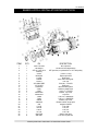
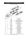
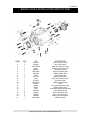
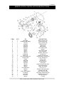
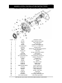
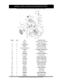
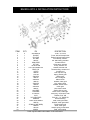
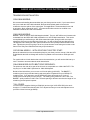
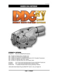
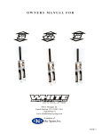
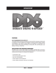
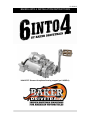
V2.102313 BAKER 6-INTO-4 INSTALLATION INSTRUCTIONS H6402P-FF Shown with optional bearing support (pn 6-4SSP-A) V2.102313 BAKER 6-INTO-4 INSTALLATION INSTRUCTIONS FEATURES 6061-T6 billet case and trap door provides more strength over the stock cast case BAKER™ Klassic Kickers gears installed with kicker transmissions Lower than stock first gear Improved neutral location with redundant neutral system and/or N1 shift drum RPM reduction at highway speeds in cruising gears Short, accurate shifts Kicker transmissions include the stainless steel BAKER™ Kick Arm assembly st Optional 3.24 1 gear available Available with 23T or 24T chain sprocket or 33T belt pulley APPLICATION 1976-Early 1984 FL/FX Shovelhead (FX with mid controls will require more modification) 1936-1964 Models Late 1984-1986 1965-1969 with modifications Custom applications NOTES Moderate skill level is required for installation. As with most things in life there are no substitutes for skill and experience. It is highly recommended by BAKER™ that when performing this task or any task related to the drivetrain components on your motorcycle, that you refer to the Factory Service Manual for you specific model of bike. PAGE 2| OVERVIEW V2.102313 BAKER 6-INTO-4 INSTALLATION INSTRUCTIONS TABLE OF CONTENTS: 2) Overview Application 3) Table Of Contents 4) Exploded View Transmission Case 5) Exploded View Gearset 6) Exploded View Transmission Case 7) Exploded View Hydraulic Side Cover 8) Exploded View & Parts List, Hydraulic Type, Function Form 9) Exploded View & Parts List, Billet Mechanical Type 10) Exploded View & Parts List, Cable Type 11) Specifications and Torque Values 12) Getting Started 13) Required Tools and Parts 14) Installation 15) Warranty 16) Disclaimer PAGE 3| TABLE OF CONTENTS V2.102313 BAKER 6-INTO-4 INSTALLATION INSTRUCTIONS EXPLODED VIEW: SHIFT SYSTEM AND FINAL DRIVE ITEM QTY PN DESCRIPTION 1 2 3 1 1 1 Nut, sprocket 10-24x1/4 Low Head Screw 23T sprocket, or optional 24T or 33T belt pulley 4 5 6 7 8 9 10 11 12 13 14 15 16 17 18 19 20 21 22 23 24 25 26 1 1 1 1 1 1 1 1 4 4 1 1 1 4 5 1 4 1 1 1 1 1 9 35211-91-6N4 10C25KLH 23T-64, (24T-64 or 32181S) 25702 33344-6-4 11165A 12067B 122-6-4 31C100KCSPR 33715-85S 4-6QEN-A 33001 23207 34904-86E 34468-56A 73468 73463 609SS 33900-59 609 101-56 102-6E 102-6F 101-6E 6N4-GAS 400-8301 ½-20 x ½” Plug Spacer,sprocket Quad seal Seal, main drive gear Fork rod 5/16-24 x 1” SHCS Shift lever 6INTO4 shift system Washer, pillow block ¼-20 x 1 ¼” SHCS Gasket, Top cover Top cover ¼-20 x 2 ¼ SHCS SS ¼-20 x 1 ¼ SHCS SS Washer, top cover Neutral switch, single pole Alignment dowel Fork, 2M Fork, 4C Fork, 3C Fork, 1M Gasket, trap door 5/16-24, 12 point nut PAGE 4| EXPLODED VIEW SHIFT SYSTEM AND FINAL DRIVE V2.102313 BAKER 6-INTO-4 INSTALLATION INSTRUCTIONS EXPLODED VIEW: GEARSET ITEM QTY PN DESCRIPTION 1 2 3 4 5 6 7 8 9 10 11 12 13 14 15 16 17 18 19 20 21 22 23 24 25 26 27 1 1 4 1 1 1 1 1 1 1 2 2 4 5 4 6 1 1 1 1 1 1 1 1 1 1 1 24040 37141 35046-36 68066 1640-DSTN 204KG 51740-001 2-6S 115-6E 25287 112-6D TRB1423-6-4 60866M 8876A 6003B 11067 62941M MS-6N4-(36,70,84) 61234M 603M2C 62212M CS-6N4 62941C 61234C 61573C 603M2C 61005C 10-32 x ½” BHCS ¾-16 Nyloc™ jam nut Nut, mainshaft 36-84 Retaining ring, trap door bearing mainshaft Bearing, trap door mainshaft Bearing, trap door countershaft Drain Plug Bearing trap door Support bridge, auxiliary fork rod 10-32 x 2 ¼” set screw Auxiliary fork rod Shim spacer th 6 gear mainshaft Needle bearing Thrust washer, gearset Retaining ring, gearset st 1 gear mainshaft Mainshaft (’36-’64,’70-E84, L84) th 4 gear mainshaft rd 3 gear mainshaft nd 2 gear mainshaft Countershaft st 1 gear countershaft th 4 gear countershaft rd 3 gear countershaft 2nd gear countershaft th 5 gear countershaft PAGE 5| EXPLODED VIEW GEARSET V2.102313 BAKER 6-INTO-4 INSTALLATION INSTRUCTIONS EXPLODED VIEW: TRANSMISSION CASE ITEM QTY PN DESCRIPTION 1 2 3 4 5 6 7 8 9 10 11 12 13 14 15 16 17 18 19 20 21 4 5 1 1 1 1 1 1 1 1 1 1 1 1 1 1 2 9 1 2 1 AV9686 AV9683 1302-334PP 6209 BK2520 1400-43PP 6497HW 12045 33114-79 70813 152-56A 555-56A-A 56-1051 66808 108-6P 73753 16583-00 AV9675 12035B HK2520 MDG-6N4 Stud, left side of case Stud, case bottom Snap ring, main drive gear Bearing, main drive gear Bearing, left case Snap ring, shifter pawl Washer, shifter pawl Seal, shifter pawl Bushing, shifter pawl Jam nut, eccentric screw Eccentric screw Shifter pawl assembly Case O-ring, speedo sensor plug Speedo sensor plug ¼-20 BHCS,speedo sensor plug 10mm alignment pin Stud, right side of case Seal, main drive gear Bearing, main drive gear Main drive gear PAGE 6| EXPLODED VIEW TRANSMISSION CASE V2.102313 BAKER 6-INTO-4 INSTALLATION INSTRUCTIONS EXPLODED VIEW: HYDRAULIC SIDE COVER ITEM QTY PN DESCRIPTION 1 2 3 4 5 6 7 8 9 10 11 12 13 14 15 16 17 18 19 20 21 22 23 24 25 26 27 28 29 30 1 1 1 1 1 1 1 1 1 1 1 1 2 1 1 2 1 1 1 1 1 1 9 1 9 1 1 1 1 1 6N4-SIDE 37088-(90,90E,MOD) 13-0128 45-9404 33430-56 33560-56 33393-50 290225 290231 292015 292014 37089-84L BD411-56 FNT-1024, BD410-56 10705-01149 66855 124-5R-B 639K269 33350-56 291222 292013 292003 31C125KCSS/P 292016 6100 .750x1.250x.250ADL 51740-001 478-56HP 2418T141 292032 Gasket, kicker cover Clutch release rod Spring, starter gear Bleeder screw Starter gear Starter clutch Key, starter clutch Washer Nut, starter clutch Nut, crank gear Washer, crank gear Actuator rod Washer, actuator rod Thrust bearing, actuator rod C-clip, actuator rod O-ring, piston Slave piston Bronze bushing Crank gear Return spring, kicker shaft Stud, return spring Shaft, Crank gear 5/16-18 x 1 ¼” Washer, crank gear shaft Washer, 5/16” AN Seal, crank gear shaft Level Plug, 3/8-24 Zero leak Hydraulic kicker cover O-ring, filler plug Fill plug PAGE 7| EXPLODED VIEW HYDRAULIC SIDE COVER V2.102313 BAKER 6-INTO-4 INSTALLATION INSTRUCTIONS EXPLODED VIEW: FUNCTION FORM HYDRAULIC SIDE COVER ITEM QTY PN DESCRIPTION 1 2 3 4 5 6 7 8 9 10 11 12 13 14 15 16 17 18 19 20 21 22 23 24 25 26 27 28 29 1 1 1 1 9 1 1 1 1 2 1 1 1 2 1 1 1 1 1 1 1 1 1 1 1 1 1 1 1 291222 292013 31588 292016 31C125KCSS/P 45-9404 479-56-P 66827 130-56F-PC 66855 124-5R-B 10705-01149 FNT-1024, BD410-56 BD411-56 125-5R 290231 290225 33393-50 33560-56 33430-56 37088-(90,90E,MOD) 13-0128 6N4-SIDE 292015 292014 33350-56 639K269 51740-001 .750x1.250x.250ADL Return spring, kicker shaft Stud, return spring 1/8” NPT plug Washer, crank gear shaft 5/16-18 x 1 ¼” SHCS SS Bleeder screw Kicker cover, Function Form hydraulic O-ring, filler plug Filler plug O-ring, hydraulic slave piston Slave piston C-clip, actuator rod Thrust bearing, actuator rod Washer, actuator rod Actuator rod Nut, starter clutch Washer Key, starter clutch Starter clutch Starter gear Clutch release rod Spring, starter gear Gasket, kicker cover Nut, crank gear Washer, crank gear Crank gear Bronze bushing Level Plug, 3/8-24 Zero leak Seal, crank gear shaft PAGE 8| EXPLODED VIEW FUNCTION FORM HYDRAULIC SIDE COVER V2.102313 BAKER 6-INTO-4 INSTALLATION INSTRUCTIONS EXPLODED VIEW: BILLET MECHANICAL SIDE COVER ITEM QTY 1 2 3 4 5 6 7 8 9 10 11 12 13 14 15 16 17 18 19 20 21 22 23 24 25 26 27 28 29 1 1 9 1 1 1 1 9 1 1 1 1 1 1 1 1 1 1 1 1 1 1 1 1 1 1 1 1 1 PN DESCRIPTION 291222 Return spring, kicker shaft 292003 Shaft, crank gear 31C125KCSS/P 5/16-18 x 1 ¼” SHCS SS 292013 Stud, return spring 292016 Washer, crank gear .750x1.250x.250ADL Seal, crank gear shaft 51740-001 Level Plug, 3/8-24 Zero leak 6100 Washer, 5/16” AN 292032 Filler plug 2418T141 O-ring, filler plug 478-56MP Kicker cover, mechanical 37074-38B Release shaft 9452K6 O-ring, release shaft 476-56 Release shaft housing 37070-39B Lever, release shaft 6443HW Washer, release shaft 6391K183 Bushing, release shaft 68077 E-clip, release shaft 6N4-SIDE Gasket, side cover 13-0128 Spring, starter gear 292015 Nut, crank gear 292014 Washer, crank gear 33430-56 Starter gear 33350-56 Crank gear 33560-56 Starter clutch 33393-50 Key, starter clutch 290225 Washer, starter clutch 290231 Nut, starter clutch 639K269 Bronze bushing PAGE 9| EXPLODED VIEW MECHANICAL SIDE COVER V2.102313 BAKER 6-INTO-4 INSTALLATION INSTRUCTIONS EXPLODED VIEW: CABLE TYPE MECHANICAL SIDE COVER ITEM QTY 1 2 3 4 5 6 7 8 9 10 11 12 13 14 15 16 17 18 19 20 21 22 23 24 25 26 27 28 29 30 31 32 33 6 1 1 1 3 3 1 1 1 2 1 1 1 1 1 1 1 1 1 1 1 1 1 1 1 9 9 1 1 1 1 1 1 PN DESCRIPTION 25C50KLHS ¼-20 x ½” LHCS 584-56P Cover, ball and ramp kicker 583-GAS Gasket, ball and ramp kicker WT3096 Inner Ramp, actuator 987687 3/8” ball bearing, actuator 3094-DSSC Actuator ferrule WT3196 Outer ramp, actuator 10705-01149 C-Clip, actuator rod FNT-1024, BD410-56 Washer, actuator rod BD411-56 Thrust bearing, actuator rod 125-5R Actuator rod 292032 Filler cap w/o-ring 13-0128 Spring, starter gear 33430-56 Starter gear 292015 Nut, crank gear 33560-56 Starter clutch 292014 Washer, crank gear 33393-50 Key, starter clutch 290225 Washer, starter clutch 33350-56 Crank gear 290231 Nut, starter clutch 6N4-SIDE Gasket, kicker cover 578-56MP Kicker cover, cable type 51740-001 Level plug, 3/8-24 Zero Leak 6100 Washer, 5/16” AN 31C125KCSS/P 5/16-18 x 1 ¼” SHCS SS 639K269 Bronze bushing .750x1.250x.250ADL Seal, crank gear shaft 292016 Washer, crank gear shaft 37088-(90,90E,MOD) Clutch release rod 292003 Shaft, crank gear 291222 Return spring, kicker shaft 292013 Stud, return spring PAGE 10| EXPLODED VIEW CABLE TYPE SIDE COVER V2.102313 BAKER 6-INTO-4 INSTALLATION INSTRUCTIONS Specifications and Torque Values TRANSMISSION FLUID: 20-24 fluid oz. of Spectro™ Heavy Duty Platinum 6 Speed Transmission Oil (pn BD-75140) TORQUE VALUES THREADLOCKER / LUBRICANT KICKER COVER 5/16” Bolts: 200-225 in-lbs (16-18 ft-lbs) KICKER CRANK GEAR Blue thread lock (242 Removable) 42-45 ft-lbs TOP COVER Red thread lock (271 Permanent) (57-61 Nm) 1/4” Bolts: 100-120 in-lbs (8-10 ft-lbs) BEARING TRAP DOOR 5/16” Nuts: Blue thread lock (242 Removable) 200-225 in-lbs (16-18 ft-lbs) Blue thread lock (242 Removable) 50-55 ft-lbs RATCHET GEAR NUT (67-75 Nm) Red thread lock (271 Permanent) 50-60 ft-lbs COUNTERSHAFT NUT (67-81 Nm) Red thread lock (271 Permanent) 50-55 ft-lbs FILL PLUG (67-75 Nm) Red thread lock (271 Permanent) MAINSHAFT NUT 30-40 in-lbs DRAIN PLUG Pipe Thread Sealant 30-40 in-lbs SPROCKET NUT Anti-Seize 60 ft-lbs (81 Nm) initial torque and then turn another 35-45 degrees; 45 degrees max. Red thread lock (271 Permanent) PAGE 11| SPECIFICATIONS AND TORQUE VALUES V2.102313 BAKER 6-INTO-4 INSTALLATION INSTRUCTIONS GETTING STARTED Thank you for buying another premium, American-made innovation from BAKER™ Drivetrain. There are a few important things to know about the BAKER™ 6-into-4 before installing this gem into your bike. Like most BAKER™ innovations, this is an upgrade and not a stock replacement. Because it is not a stock replacement, there are sometimes minor fitment issues you might encounter during the install. The type of fitment issue varies from bike to bike. The first issue is usually exhaust clearance. The BAKER™ 6-into-4 is 1 5/8” wider than stock, causing it to sometimes interfere with exhaust fitment. There are companies making aftermarket exhaust that will clear the BAKER™ 6-into-4 with no problem. Most stock exhausts do not clear this transmission. This clearance issue is caused because the BAKER™ 6-into-4 has two more gear pairs, which means 50% more transmission in less than 2 inches of more space. The only other issue that most folks encounter is due to the fact that the BAKER™ 6-into-4 is a direct bolt in, because of the different options on motorcycles there will be individual component clearance issues. This is caused by the vast array of aftermarket parts that have been available during the 50 years that the stock transmission was used. With varying individual components bike to bike, BAKER™ cannot guarantee individual component clearance. We can however, guarantee our 6-into-4 you’re about to slam in there, so we offer an incredible 5yr, 50k mile warranty on it and you can read all about that in the back of these instructions. Remember, BAKER™ Drivetrain is always standing by with knowledgeable tech support if you should encounter any issues during your install. PAGE 12| GETTING STARTED V2.102313 BAKER 6INTO4 INSTALLATION INSTRUCTIONS TOOLS, RESOURCES, REQUIRED PARTS Factory Service Manual For Your Motorcycle Factory Parts Manual For Your Motorcycle H-D™ Clutch hub puller hand tool Common American sockets and open end wrenches Impact Driver Torque Wrench (reads both in inch pounds and foot pounds) Brake Bleeder Pump (for hydraulic type) NOTES: HYDRAULIC VERSION ONLY To complete the Installation of the hydraulic kicker 6-INTO-4, the following parts will have to be procured to complete the job: Hydraulic Fluid, BAKER™ Recommends: H-D™ Dot 5 Brake Fluid, PN 99902-77 Correct length AN -3 Brake Line 10mm Banjo Fitting & Washers For Both Ends Of Brake Line 3/8”-24 Banjo Bolt For The Side Cover End Of The Brake Line 11/16” Diameter Bore Hydraulic Clutch Lever Assembly or H-D™ Assembly PAGE 13| REQUIRED TOOLS AND PARTS V2.102313 BAKER 6INTO4 INSTALLATION INSTRUCTIONS TRANSMISSION INSTALLATION: 1936-1964 MODELS: We recommend installing the transmission per your factory service model. If you have ordered the 6-into-4 with the 1936-1964 mainshaft; the dust shield splash guard will need to be modified to clear the splines of the output gear. This application is recommended for use with tin primaries. Stock exhaust will not fit. Your exhaust will either need to be modified or an aftermarket exhaust will need to be installed. 1965-1969 MODELS: BAKER™ does not offer a 1965-1969 length mainshaft. There is .485” difference in between the mainshafts from the OEM 1965-1969 mainshaft to our 1970-E1984 transmission. This can be accomplished by manufacturing a .485 offset transmission plate. Doing this will also require altering the 5th mount on the right lower frame tube. As well as flipping the provided sprocket 180 degrees and installing the .485” spacers between the inner primary and transmission case ears. Typically the rear ear is going to be of very close tolerance to the swing arm mount on the frame on the early Duo-Glide bikes and may require clearance. 1970-E1984 MODELS – WITH OR WITHOUT ELECTRIC START: Mount the transmission to the transmission plate per your factory service manual. With the 1970E1984 Models the shift rod linkage will need to be updated to be used with an EVO style shift lever. For models with an oil tank bracket that runs to the transmission, you will need to fabricate up a new ‘Z’ bracket to accommodate the wider transmission. 1984-1986 MODELS-WITH BELT DRIVE SECONDARY: The splines on the main drive gear of the 6-into-4 are comparable to a 1982-1984 FXR™. The key way is of a 1984-1989 5 speed and or 1984-1986 4speed. Belt drive final drive bikes, you must use our 33 tooth pulley (pn32181S). The BAKER™ maindrive gear is longer and the bearing and seal system is updated from your OEM H-D™ maindrive gear. If you attempt to use the OEM pulley there will be almost a ¼ inch off interference from the pulley to inner primary. The factory pulley measures 1.941” wide. The BAKER™ pulley measures 1.600” wide. The back spacing is different as well as the length of our miandrive gear and sprocket spacer. **ALL YEARS: You must use the supplied 3/8-24 (pn37090-6-4) and seal (pn.3125x.875x.250) in the stock clutch nut. For aftermarket clutches with 7/16” adjuster screws you must order adjuster screw pn 37091-6-4 and lock nut (pn36258). PAGE 14| INSTALLATION V2.102313 BAKER 6INTO4 INSTALLATION INSTRUCTIONS TERMS: SPECIAL ORDERS A minimum $500 deposit is required with all special orders. Special orders include unique case finishes, unique side door requests (i.e.; wrinkle black door or no logo). ALL OTHER ORDERS Orders can be pre-paid using VISA, MasterCard or American Express. Prices shown are F.O.B. Haslett; MI. BAKER™ provides free UPS ground shipping on all retail orders for complete transmissions or transmission kit. UPS air shipment is available upon request. Customer is responsible for air shipment premiums. LIMITED WARRANTY BAKER™ 6-INTO-4 transmissions are guaranteed to the original purchaser to be free of manufacturing defects in materials and workmanship for a period of 5 years or 50,000 miles from the date of purchase whichever comes first If the product is found by BAKER™ to be defective, such products will, at the option of BAKER™, be replaced or repaired at cost to BAKER™. In the event warranty service is required, the original purchaser must call or write BAKER™ immediately with the problem. If it is deemed necessary for BAKER™ to make an evaluation to determine whether the transmission assembly or transmission kit is defective, the entire transmission assembly, whether originally purchased as an assembly or kit, must be properly packaged and returned prepaid to BAKER™ with a copy of the original invoice of purchase. If after an evaluation has been made by BAKER™ and a defect in materials and/or workmanship is found, BAKER™ will, at BAKER™ option, repair or replace the defective part of the assembly. Warranty card must be returned within 45 days of purchase to be valid. ADDITIONAL WARRANTY PROVISIONS This limited warranty does not cover labor or other costs or expenses incidental to the repair and or replacement of BAKER™ products. This warranty does not apply if one or more of the following situations is judged by BAKER™ to be relevant: improper installation, accident, modification (including but not limited to use of unauthorized parts), racing, high performance application, mishandling, misapplication, neglect (including but not limited to improper maintenance), or improper repair. BAKER™ shall not be liable for any consequential or incidental damages arising out of or in connection with a BAKER™ transmission assembly, transmission kit, swingarm, fender, component or part. Consequential damages shall include without limitation, loss of use, income or profit, or losses sustained as the result of injury (including death) to any person or loss of or damage to property. BAKER™ transmissions, transmission kits, and Wide Tire Kits are designed exclusively for use in Harley-Davidson® motorcycles. BAKER™ shall have no warranty or liability obligation if a BAKER™ part is used in any other application. PAGE 15| WARRANTY V2.102313 BAKER 6INTO4 INSTALLATION INSTRUCTIONS DISCLAIMER The words Harley™ and H-D™ are registered trademarks and are for reference only. Use of H-D™ model designations and part numbers are for reference only. BAKER™ Drivetrain has no association with, and makes no claim against, these words, trademarks, or companies. It is the sole responsibility of the user to determine the suitability of this product for his or her use, and the user shall assume all legal, personal injury risk and liability and all other as well as all other obligations, duties and risks associated therewith. CUSTOMER SUPPORT For any installation or service questions, please contact our BAKER™ technical department toll free 1-877-640-2004. Baker Drivetrain 9804 E. Saginaw Haslett, MI. 48840 USA On the web: www.bakerdrivetrain.com PAGE 16| DISCLAIIMER