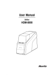
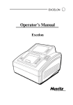
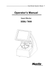
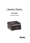
Download Automatic Tracer-Blocker HAB-8000 Huvitz
Transcript
1 User Manual Autoblocker HAB-8000 1 2 HUVITZ KAIZER HAB-8000 IMPORTANT NOTICE This product may malfunction due to electromagnetic waves caused by portable personal telephone, transceivers, radio-controlled toys, etc. Be sure to avoid having the above objects, which affect the normal operation of the product, brought near the product. The information in this publication has been carefully checked and is believed to be entirely accurate at the time of publication. HUVITZ assumes no responsibility, however, for possible errors or omissions, or for any consequences resulting from the use of the information contained herein. HUVITZ reserves the right to make changes in its products or product specifications at any time and without prior notice, and is not required to update this documentation to reflect such changes. 9000ENGL201-A Ver 1.0 (Jun. 2013) ©2013 HUVITZ Co., Ltd. 298-29 Gongdan-ro, Gunpo-si, Gyeongi-do 435-862, Republic of Korea All rights reserved. By copyright law, you are not allowed to copy any parts of this manual without prior permission from HUVITZ Co., Ltd. 3 CONTENTS 1. Introduction ...................................................................................................................................... 6 1.1. 1.2. 1.3. 2. Safety Information............................................................................................................................ 8 2.1. 2.2. 2.3. 2.4. 3. Installation Procedure........................................................................................................... 17 Frame Reader ................................................................................................................................. 18 5.1. 5.2. 5.3. 6. Front View ............................................................................................................................ 15 Rear View ............................................................................................................................ 15 Standard Accessories (Tool Box) .......................................................................................... 16 Installation ...................................................................................................................................... 17 4.1. 5. Introduction ............................................................................................................................ 8 Safety Symbols ...................................................................................................................... 9 Environmental Considerations .............................................................................................. 10 Safety Precautions ............................................................................................................... 12 Autoblocker (HAB-8000) ................................................................................................................ 15 3.1. 3.2. 3.3. 4. Main Features ........................................................................................................................ 6 System Configuration ............................................................................................................. 7 Classification .......................................................................................................................... 7 Frame Reader Button ........................................................................................................... 18 Frame Tracing ...................................................................................................................... 19 Pattern Tracing ..................................................................................................................... 19 Auto Blocker User Interface .......................................................................................................... 21 6.1. Main Screen ......................................................................................................................... 21 6.1.1. Side Button ................................................................................................................................................21 6.1.2. Job Management.....................................................................................................................................23 6.1.3. Frame Information ..................................................................................................................................25 6.1.4. Layout Option ...........................................................................................................................................25 6.1.5. Edging Option ..........................................................................................................................................29 6.1.6. Lens Information ......................................................................................................................................33 6.1.7. Function Button .......................................................................................................................................37 6.2. Blocking Screen ................................................................................................................... 38 6.2.1. Lens Detection Mode ............................................................................................................................38 6.2.2. Lens Type ....................................................................................................................................................39 6.2.3. Lens Power .................................................................................................................................................39 6.2.4. Lensmeter ...................................................................................................................................................40 6.2.5. Blocking Mode .........................................................................................................................................40 6.2.6. Blocking / Sending job..........................................................................................................................40 6.3. Blocking for the Different Types of Lenses ............................................................................ 41 6.3.1. Single Vision Lens ...................................................................................................................................41 6.3.2. Bi-focal Lens ..............................................................................................................................................45 6.3.3. Progressive Lens ......................................................................................................................................47 3 4 HUVITZ KAIZER HAB-8000 6.3.4. Progressive Lens – Semi Auto ............................................................................................................48 6.3.5. 3-dot Lens ..................................................................................................................................................51 6.3.6. Frame Relocation .....................................................................................................................................52 6.3.7. Manual Blocking Mode .........................................................................................................................54 6.4. Job Manager ........................................................................................................................ 58 6.4.1. Job Selection Tab.....................................................................................................................................58 6.4.2. Function Button .......................................................................................................................................59 6.4.3. Waiting Job Tab........................................................................................................................................59 6.4.4. Working Job ..............................................................................................................................................60 6.4.5. Completed Job Tab .................................................................................................................................60 6.4.6. Job Searching............................................................................................................................................61 6.5. Digital Pattern ...................................................................................................................... 63 6.5.1. Enlargement/Reduction.........................................................................................................................64 6.5.2. Near Vision Area Enlargement/Reduction .....................................................................................65 6.5.3. Rotation .......................................................................................................................................................66 6.5.4. Partial Modification.................................................................................................................................68 6.5.5. Reset .............................................................................................................................................................69 6.5.6. Toggle R/L Sync .....................................................................................................................................70 6.5.7. Exit .................................................................................................................................................................70 6.6. Hole Editor ........................................................................................................................... 72 6.6.1. Upper Side of Hole Editor ...................................................................................................................73 6.6.2. Working Area ............................................................................................................................................73 6.6.3. Preview ........................................................................................................................................................74 6.6.4. Function Buttons......................................................................................................................................75 6.6.5. List of Hole/Slot .......................................................................................................................................81 6.6.6. Property of Hole/Slot .............................................................................................................................83 6.7. Digital Scan + Tracer UI ....................................................................................................... 84 6.8 7. 6.7.1. Digital Scan ................................................................................................................................................84 6.7.2. Tracer UI (Frame) .....................................................................................................................................85 6.7.3. Tracer UI (Pattern)....................................................................................................................................87 Job editor ............................................................................................................................. 89 Configuration ................................................................................................................................. 91 7.1. Preference ........................................................................................................................... 92 7.1.1. General ........................................................................................................................................................92 7.1.2. Layout ..........................................................................................................................................................94 7.1.3. Edging ..........................................................................................................................................................95 7.1.4. Hole Editor .................................................................................................................................................96 7.1.5. Digital Pattern ...........................................................................................................................................97 7.1.6. Communication Port ..............................................................................................................................98 7.1.7. Lensmeter ...................................................................................................................................................99 7.1.8. Tracer ......................................................................................................................................................... 100 5 8. System Maintenance.................................................................................................................... 101 8.1. Automatic Calibration of Frame Reader ......................................................................... 101 8.1.1. Stroke Calibration ................................................................................................................................. 102 8.1.2. Frame Calibration ................................................................................................................................. 102 8.1.3. Pattern Calibration ............................................................................................................................... 102 8.2. Save Image ....................................................................................................................... 103 8.3. Test Mode ......................................................................................................................... 107 8.4. Date & Time ...................................................................................................................... 107 8.5. Touch Test ........................................................................................................................ 108 8.6. Configuration Management ............................................................................................. 109 8.7. S/W Upgrade ..................................................................................................................... 110 8.8. Maintenance Code ........................................................................................................... 112 8.9. Maintenance Tips ............................................................................................................. 113 9. 8.9.1. Fuse Replacement ................................................................................................................................ 113 8.9.2. Regular Maintenance .......................................................................................................................... 113 8.9.3. Cleaning ................................................................................................................................................... 113 Troubleshooting Guide ................................................................................................................ 114 10. Specifications and Accessories .................................................................................................. 115 10.1. 10.2. 10.3. Standard Accessories......................................................................................................... 115 Specifications ..................................................................................................................... 116 Drawings of System ........................................................................................................... 117 11. SERVICE INFORMATION.............................................................................................................. 118 5 6 HUVITZ 1. KAIZER HAB-8000 Introduction This product is Auto Blocker HAB-8000, lenses can be analyzed and blocked automatically with this machine. So the HAB-8000 eliminates the need for manual inspection or manual blocking of the lens. Also, HAB-8000 is able to read the frame with simple steps. 1.1. Main Features This product can block all kinds of lenses that include the normal lens without 3 dot, the bifocal lens, the progressive lens and the lens with 3 dot. 10.4” TFT-LCD True color display device and touch screen are harmonized to offer the actual size (Frame, PD and FPD etc.) display and the maximum convenience for everyday use The Frame Reader Module reads the frame as well as the pattern, and then sends the data to main GUI display module. This product includes not only the image processing module but also the lensmeter module so that it can block from a normal lens without 3 dot to a progressive lens. User can design all information about layout and edging at one page, and send it to other two edger machines at a same time. Graphically Designed Test Mode enables the operator to effectively perform the routine maintenance without the technical assistance Any shape and material of a frame from rimless to goggles are automatically and precisely scanned with 3D technology that guarantees no margin of error. The Digital Scanning technology can scan a frame shape for a demo lens without a conventional tracer. This provides you an enormous convenience and a time saving. Frame data is saved in SD memory card permanently. Therefore, you can load them whenever you want. The complete harmony between this blocking machine and the edger machine will accomplish the full automation of edging processes. 7 1.2. System Configuration Auto Blocker (HAB-8000) 1.3. Edger (HPE-8000) Classification This device complies with Part 15 of the FCC Rules. Operation is subject to the following two conditions: (1) this device may not cause harmful interference, and (2) this device must accept any interference received, including interference that may cause undesired operation. Class A equipment Class A equipment is intended to be used in an industrial environment. In this document for the user, a statement shall be included drawing attention to the fact that there may be potential difficulties in ensuring electromagnetic compatibility in other environments, due to conducted as well as radiated disturbances. Protection against electric shock: Class I(earthed) Measurement Category: CAT II Pollution Degree: 2 7 8 HUVITZ 2. KAIZER HAB-8000 Safety Information 2.1. Introduction Safety is everyone’s responsibility. The safe use of this machine is largely dependent upon the installers, users, operators, and managers. It is prerequisite to read and understand these specifications before installing, using, cleaning, fixing or revising. Fully understanding the whole instructions must be the first priority. For this reason, the following safety notices have been placed appropriately within the text of this manual to highlight safety related information or information requiring special emphasis. All users, operators, and maintainers must be familiar with and pay particular attention to all signs of Warnings and Cautions. ! WARNING “Warning” indicates the presence of a hazard that could result in severe personal injury, death or substantial property damage if ignored. ! CAUTION “Caution” indicates the presence of a hazard that could result in minor injury, or property damaged if ignored.- NOTE This is used to emphasize essential information. Be sure to read this information to avoid operating the device incorrectly. 9 2.2. Safety Symbols The International Electrotechnical Commission (IEC) has established a set of symbols, which are listed below. This applies only to the instrument that has the certification symbol printed explicitly on the product label or sticker. I and O on power switch represent ON and OFF respectively. This symbol identifies caution, risk of danger. Ensure you understand the function of this control before using it. Control function is described in the appropriate User’s or Service Manual. Protective Earth Connection Disposal of your old appliance 1. When this crossed-out wheeled bin symbol is attached to a product it means the product is covered by the European Directive 2002/96/EC. 2. All electrical and electronic products should be disposed of separately from the municipal waste stream via designated collection facilities appointed by the government or the local authorities. 3. The correct disposal of your old appliance will help prevent potential negative consequences for the environment and human health. 4. For more detailed information about disposal of your old appliance, please contact your city office, waste disposal service or the shop where you purchased the product. Alternating Current 9 10 HUVITZ 2.3. KAIZER HAB-8000 Environmental Considerations Avoid the following environments for operation or storage: Where the machine is exposed to water vapor. Don’t operate the machine with wet hands Where the machine is exposed to direct sunlight. Where there are big changes in temperature. Optimal temperature range for normal operation is from 10C to 40C. (Humidity : 30 ~ 80%) Where there is a hot equipment nearby Where the humidity is extremely high or there is a ventilation problem. Where the machine is exposed to excessive shocks or vibrations. Where the machine is exposed to chemical material or explosive gas. Be cautious so that things like dust and metal do not fall inside the machine. 11 Don’t disassemble or open the product. HUVITZ does not take responsibility for the possible problems Be careful not to block the fan located on the backside of the machine. Don’t plug the AC power cord into the outlet unless all parts of the machine are completely connected. Otherwise, it will cause severe damage on the machine. Pull out the power cord with holding the plug, not the cord. To avoid risk of electric shock, this equipment must only be connected to a supply mains with protective earth. This instrument must be followed by these following conditions: 1. Operation An ambient temperature range of 10℃ ~ 40℃ (50°F ~ 104°F) A relative humidity range of 30% ~ 80% An atmospheric pressure range of 800 ~ 1060hpa 2. Transportation An ambient temperature range of -25℃ ~ 70℃ (-13°F ~ 158°F) A relative humidity range of 10% ~ 95% (with non-condensing) An atmospheric pressure range of 500 ~ 1060hpa 3. Storage An ambient temperature range of -25℃ ~ 70℃ (-13°F ~ 158°F) A relative humidity range of 10% ~ 95% (with non-condensing) An atmospheric pressure range of 700 ~ 1060hpa Please avoid where the equipment is exposed to excessive shocks or vibration. Operation time: max 6 min for short-term operation 11 12 HUVITZ 2.4. KAIZER HAB-8000 Safety Precautions This machine has been developed and tested according to safety standards as well as national and international standards. This guarantees a very high degree of safety for this device. HUVITZ is legally required to inform the users of all the information regarding safety. Observance of the instructions is the requirement for the safety. Therefore, please read carefully all instructions before switching on this machine. For more detailed information, please contact our Customer Service Department or one of our local agencies 1. This equipment must not be used (a) in an area that is in danger of explosions and (b) in the presence of flammable, explosive, or volatile solvent such as alcohol, benzene or similar chemicals. 2. Do not place or store this machine in humid area. Humidity should be maintained between 30 and 80% for normal operation. Do not expose the device to water splashes, dripping water, or sprayed water. Do not place containers with fluids, liquids, or gases on top of this machine 3. The machine must be operated by a trained and qualified person or under his or her supervision 4. Repair of this machine must be conducted by HUVITZ’s service technicians or other authorized persons. 5. Maintenance by users must observe the User’s Manual and Service Manual. Any additional maintenance may only be performed by HUVITZ‘s service technicians or other authorized persons. 6. Manufacturers are responsible for the safety, reliability, and performance of this machine only when the following requirements are fulfilled: (1) When the machine has been installed in a proper area, following the manual. (2) When the machine has been operated and maintained according to the manual and service manual. 7. Manufacturers are not responsible for the damages caused by unauthorized alterations. Such tampering will forfeit any rights to receive services during the term of guarantee. 8. This machine must be connected with the accessories supplied by HUVITZ. If you are to use other accessories, their safety or usability must be checked and proved by their manufacturers or HUVITZ. 9. Only those who have undergone proper training and instructions are authorized to install, use, operate, and maintain this machine. 10. Keep the User’s Manual and Service Manual in a place easily accessible at all times for persons operating and maintaining the equipment. 11. Do not apply excessive force to cable connections. If the cable does not connect easily, make sure that the connector (plug) is appropriate for the receptacle (socket). If you caused any damage to a 13 cable connector(s) or receptacle(s), let the damage(s) be repaired by an authorized service technician. 12. Please do not pull on any cable. Always grab the plug when disconnecting cables. 13. Before you use, check the exterior of the machine and its conditions 14. Do not block any ventilation outlet necessary for proper heat dissipation. 15. If smoke, sparks or any abnormal noise or smell is noticed coming from the machine, please switch the power off immediately and pull out the plug. 16. When you carry this product, please use a hand cart. At least three people are required to lift the machine. If you want to move the product to other area, please contact customer service center. 17. To avoid the risk of electric shock, , this machine must only be connected to protective earth 18. The machine may be impaired if it is used in a manner not specified by the manufacturers or manual. ! WARNING Do not put your hands into the machine while blocking. Otherwise, it may cause serious injury. Do not block without lens adaptor, otherwise the lens may be broken or scratched. Do not block when there is no lens on the lens supporter. Otherwise it may cause malfunction of the product. The machine should be properly installed and operated based on the instructions on this manual. If the power is turned on without removing fixing materials like several styrofoams, it may cause damage to the product and cause malfunction of the product. Do not disassemble the product without proper training. It may cause electric shock, serious injury during the operation or cause malfunction of the product. The product should be properly installed and maintained at where the ground is even and flat. Otherwise, it may affect the normal operation of the product. Be sure that the stylus of frame reader is not interfered with the human body or other objects during the operation. Otherwise, it may cause injury or malfunction of the product. Do not force on the stylus of frame reader. It may cause malfunction of the product. 13 14 HUVITZ KAIZER HAB-8000 ! CAUTION When moving the machine, first fix the stage and check whether the power supply is off. Then, two or more persons should lift the bottom of the product with both hands. When setting down the machine, make sure not to be interfered with the obstacles. Set down the product slowly in order to prevent any injury of human body or damage to the product. When moving the machine, make sure the locking device and the screw for the cover are properly tightened. When wrapping the machine, use recommended packaging and shock-absorbing materials in order to prevent damage during the transportation. Be sure to use the standard accessories or tools provided together with the product for the maintenance. Otherwise, it may cause the malfunction of the product. Changes or modifications not expressly approved by the party responsible for compliance could void the user's authority to operate the equipment. NOTE This equipment has been tested and found to comply with the limits for a Class A digital device, pursuant to Part 15 of the FCC Rules. These limits are designed to provide reasonable protection against harmful interference when the equipment is operated in a commercial environment. This equipment generates, uses, and can radiate radio frequency energy and, if not installed and used in accordance with the instruction manual, may cause harmful interference to radio communications. Operation of this equipment in a residential area is likely to cause harmful interference in which case the user will be required to correct the interference at his own expense. 15 3. 3.1. Autoblocker (HAB-8000) Front View Display (Touch Screen) SD card slot Blocking Arm Shutter Frame Reader Button 3.2. Frame Reader Cover Rear View Interface Terminal - EDGER 1 - EDGER 2 - Barcode Reader - Tracer Out Function Button Main Power Input and Fuse 15 16 HUVITZ 3.3. KAIZER HAB-8000 Standard Accessories (Tool Box) Lens Supporter Lens Supporter for Frame Change Lens Supporter for Digital Scanning Pattern Holder Touch Pen Standard Pattern Standard Frame NOTE Only 3M LEAP-III™ is available for this product. Otherwise, the lens axis may move We do not provide a sticker for Super Hydrophobic Lens, but you should use qualified ones, or the lens axis may move 17 4. Installation 4.1. ① Installation Procedure Remove the shock-absorbing materials from the packing box and take out the auto blocker carefully. ② ③ Remove the shock-absorbing materials from the blocking arm and the workspace of Stylus. Plug the Power Cable into the socket at the rear side of the product and turn on the power to check the initial operation. ④ If the initial operation is successful, connect Edger and Auto blocker using 9-pin D-sub Crossed Interface Cable. NOTE Keep the shock-absorbing material in the tool box and use them again when you move the machine 17 18 HUVITZ 5. KAIZER HAB-8000 Frame Reader 5.1. Frame Reader Button FRAME Frame Material LED STOP Material Selection - FRAME Button You must press FRAME button and select one of the following options (frame materials) before the frame is traced. METAL HARD PLASTIC (PLASTIC) SOFT PLASTIC (OPTYL) The specified value is used in Edger for the size adjustment. Curve Selection - FRAME Button If the pattern or the demo lens is placed in the tracer, the FRAME button is automatically changed from material selection to curve selection. METAL – LO CURV (2D Tracing) HARD PLASTIC - HI CURV (3D Tracing) With ‘HI CURV’ mode, the tilt correction will be conducted automatically. Therefore, select HI CURV mode for a lens with extreme curve. L / BOTH / R Button - Tracing BOTH Two eye tracing. This is only for frame tracing. R Right eye tracing. L Left eye tracing. STOP Button Stop tracing. 19 5.2. Frame Tracing ① Place the frame between the upper grippers and the lower grippers. ② Move the frame in order that the bridge of frame is located at the central position between the left and right side grippers. ③ Press the FRAME button to select the frame material. ④ 5.3. ① Press the Reading Button (BOTH, R, L). Pattern Tracing Make a marked spot on the optical center of the demo lens by using Lensmeter. ② Demo Lens Block the Lens Adaptor at the center of the marked spot by using Blocker. ③ Place it on the Pattern Holder. ④ Press the FRAME button and select the tracing mode Lens Adaptor (LO CURV, HI CURV). ⑤ Press the Reading Button (R, L). [How to place the Pattern Holder to Gripper] 19 20 HUVITZ KAIZER HAB-8000 NOTE The data will be automatically transmitted after finishing the tracing. When tracing the single side (R or L), the data for R or L will be symmetrically copied to the data of the other side automatically. When tracing pattern or demo lens, press the ‘L’ or ‘R’ button for more than 3 seconds to execute concave shape tracing mode. When tracing frame, press the ‘L’, ‘BOTH’ or ‘R’ button for more than 3 seconds to execute concave shape tracing mode. (if MENU >> ETC >> SEMI-AT option is set to YES, Semi-Automatic tracing mode will be executed instead of concave mode) Semi-Automatic tracing mode is useful for tracing the frame with the lopsided groove. In this manual, both “Tracer” and “Frame Reader” are used. 21 6. Auto Blocker User Interface 6.1. Main Screen Side Button Function Button 6.1.1. Frame Information Job Number Edging Option Lens Information Layout Option Function Button Side Button 1 ① Press the R button to select right side. 2 ② Press the L button to select left side. 21 22 HUVITZ KAIZER HAB-8000 NOTE Each side of frame shape is exchanged by pressing the R button for a while. The function of exchange R/L is useful when you selected wrong side while reading demo lens or patterns. (Message pops up when press the R button for a while) (Left and Right sides are exchanged. The other job options remain unchanged) 23 6.1.1. 1 Job Management 3 2 c 6.1.2. ① New : Clear current job screen and wait new job. ② Job Number : Display current job number (Press the button to change job number) ③ Job Manager : Press the job manager button to load a new job or move on to another job NOTE Virtual Keyboard Use the virtual keyboard to change Job number. 6 1 2 3 5 4 ① Job number Value ② Backspace ③ Apply ④ Reset (Cancel) – If you press the button, the value goes back to original value. If you press the reset button one more time, the virtual keyboard disappears ⑤ Move cursor ⑥ Cancel (Close) – Close the virtual keyboard without saving changes. 23 24 HUVITZ KAIZER HAB-8000 NOTE Following additional functions are available by pressing ‘Job Management’ button for a You can save current job on SD card by pressing ‘Job Number’ for a while. You can start jobs with edger or remote edging host pc by pressing ‘Job Manager’ button while. for a while. The function of job request works only when communication option on configuration menu is set properly. 25 6.1.3. Frame Information 1 2 4 3 ① Frame Curve ② Circumference ③ Minimum Lens Diameter ④ Width/Height 6.1.4. 6.1.5. Layout Option 1 9 2 2 5 6 3 4 7 8 6.1.6. ① Binocular PD: Input prescribed binocular PD value. ② Monocular PD : Input PD values for each side (L/R) ③ Bridge Size (DBL): Input value of bridge size. ④ FPD: Input value of FPD. ⑤ OH Type: Select one of three, ΔY, Box Height, Mix Height. ⑥ OH (Optical Height): Input OH value. ⑦ Frame Material : Display frame material ⑧ Touch Screen Lock On/Off ⑨ Blocking Offset: Display movement amount of the les to perform Boxing center blocking with manual blocker. 25 26 HUVITZ KAIZER HAB-8000 NOTE When you input Binocular PD value, Monocular PD values for each side are automatically calculated and vice versa. When you input Bridge Size value, FPD value is automatically calculated and vice versa. In case of Two Eye Tracing, the value of FPD will be automatically transmitted and displayed. In case of pattern tracing, be sure to change the standard value to the actual Bridge Size. In case of One Eye tracing, it will be helpful to use Bridge Size Input function. (It is much easier to measure the Bridge Size) Measure B, not A, for the Bridge Size. Remember that the Bridge Size is not from frame to frame, but from lens to lens. OH value is recalculated when you change OH type. The exact meaning of the mix height and the box height is as following. Mix Height Box Height It is important to measure the optical height of the patient precisely when edging a progressive lens. Sometimes, too short optical height might cut out the near vision area. 27 NOTE Layout information, edging information and lens information can be modified in advance before or while tracing the frame information by frame reader or digital scan. The modified information will be applied to the new job from the frame reader or digital scan. In layout information, dialog PD, OH, Bridge Size, FPD are mandatory value. The color of input box of these values is changed when you input value. Blanked box is colored yellow. It changes into white when you input value. If frame reader traces shape of frame for both side, FPD value is calculated automatically. Therefore, input boxes of bridge size and FPD are displayed white. 27 28 HUVITZ HAB-8000 KAIZER Warning message pops up if you start edging with the blanked box remained. But, this warning message pops up only when the warning option is turned on in the Preferences menu. NOTE Numeric Keypad Click the value you want to change then this numeric keypad will pop up. 1 9 2 3 4 5 ① Name of the value ② Range of the value ③ Value ④ Increase/Decrease ⑤ Backspace ⑥ Reset (Cancel) - If you press it, the value goes back to original value. If you press it one more time, the numeric keypad disappears. ⑦ Change Sign ⑧ Apply ⑨ Cancel – Close numeric keypad without saving the changes. Reset button is helpful when you are in trouble with small size of cancel button. 6 8 7 29 6.1.7. Edging Option 1 4 6 5 2 7 3 ① Edging Type Bevel Flat Grooving Mini Bevel Asymmetric Bevel NOTE Available edging types can vary by wheel types of the edger. Normal Type (RPG, RPW) Asymmetric Type (RPA, RPWA) 29 Semi U Bevel 30 HUVITZ KAIZER HAB-8000 NOTE You can input additional parameters according to the selected edging type. Grooving 1 2 Groove Depth ② Groove Width ① Bevel Height ① Front Height ② Rear Height ① Tip Width ② Rear Height Mini Bevel 1 ① Asymmetric Bevel 1 2 Semi U Bevel 1 2 31 NOTE After you’ve selected grooving as the edging type, you can select partial grooving by pressing ‘Edging type’ button for a while. There are three ways for support to partial grooving. Grooving Partial Grooving (Flat + Grooving) Hybrid Grooving (Bevel + Grooving) Partial Bevel (Bevel + Flat) Relevant icon is displayed at edging type when partial grooving is selected. To cancel the partial grooving mode, press the edging type button and change into another mode. Processing with partial grooving needs an editing step of partial grooving for set boundary position after feeling process. ① Bevel/Groove Position Front % Front mm Rear mm ② Size Adjustment (-2.0 ~ 2.0mm) ③ Polishing Polishing Off Base Curve Polishing On High Polishing 31 Auto Manual 32 HUVITZ ④ KAIZER HAB-8000 Front Safety Beveling Safety Beveling Off ⑤ Safety Beveling On Rear Safety Beveling Safety Beveling Off Safety Beveling Small Safety Beveling Large NOTE Polishing / Safety Beveling touch screen area 1 3 2 ① Polishing On/Off ② Front Safety Beveling On/Off ③ Rear Safety Beveling Off/Small/Large When you selected ‘Asymmetric Bevel’ or ‘Semi-U Bevel’, Rear Safety Beveling is not available. When you selected ‘Hybrid Grooving’, Safety Beveling is not available. ⑥ Lens Material Plastic Polycarbonate Hi-Index Glass Trivex® 33 NOTE If the wheel type of the edger is Asymmetric or Wide, Glass lens cannot be selected. Glass lens cannot be processed in the following edging process. Polishing, Grooving, Milling, Drilling(HDM-8000) 6.1.8. Lens Information 1 2 3 4 ① ② Lens Type Single Bi-focal Bi-focal Bi-focal Vision (Flat) (Round) (Curved) Blocking Mode Optical Center ③ Boxing(Frame) Center Auto/Manual Blocking Mode Optical Center Boxing(Frame) Center 33 EX 3-dot Progressive 34 HUVITZ ④ HAB-8000 KAIZER Safety Mode Safety Mode Off Safety Mode On NOTE In manual blocking mode, you can change the guideline according to the lens type. Normal lens ① 3-dot length ① Near vision area diameter ① Eye point height ② Axis length 1 Bi-focal lens 1 Progressive lens 1 2 35 NOTE Boxing Center is useful for the following cases. When PD is in eccentric position When frame is horizontally wide Super Hydrophobic Lens or Ultra Hi-Index Lens When you choose the options for Bi-Focal, Near Vision Shape will be displayed on the screen. If you input the diameter, you can see the frame shape similar to the actual lens shape and check the interference. According to the Edging Options, you can control the Beveling and Grooving position. Ratio(%) from the front side of the lens Distance(mm) from the front side of the lens Distance(mm) from the rear side of the lens Adjust the position according to the lens base curve and the minimum thickness (0~10) The position determined automatically to follow the frame curve Adjust the position manually Final outputs according to the edging options are different just like the following pictures. [Ratio(%) mode from the front side] Please be cautious that the thinnest part of a lens may be broken when you use ratio (%) mode from the front side. 35 36 HUVITZ KAIZER HAB-8000 [Distance(mm) mode from the front side] Using the distance (mm) mode from the front side, the operator can designate the specific moving distance. However, if the thickness of the thin part is less than twice the designated value, the machine will process at internal center, which is 50% in ratio. Base Curve (-) Lens (+) Lens [Base curve mode] In the base curve mode, base curves of (+) lenses and (-) lenses exist the opposite side. In this mode, the bevel or grooving line always passes the mid of the thinnest parts, one of which is located at the midst zone of (-) lens and the other is located at the edged zone of (+) lens. And much bigger position value makes the curve closer to the base curve. Frame Material, Lens Material and Lens Thickness may affect the quality of Lens Fitting. If needed, execute the Size Adjustment in advance. Frequently used Adjustment Value can be saved at “Frame Fitting” in “Configuration Menu”. ! CAUTION Be sure to carry out the Edging Process in Safety Mode when the lens is fragile or the axis easily moves. Grooving and Polishing is not available for the Glass Lens. Be sure the material of lens is matched with the job options selected in the display before starting the edging process. Always be sure to use a new Tape or Sticker and remove moisture on the Lens surface. The safety beveling for glass lenses should be performed both at front and rear side. Otherwise, it will cause damage to the human skin or eyes. To prevent the distortion of axis, you must use stickers provided by lens manufacturers for blocking of hydrophobic lenses. We do not guarantee the quality of the stickers. 37 6.1.9. Function Button 3 1 4 2 5 ① Expert Job Editor ② Menu ③ Digital Designer (Digital Pattern + Hole Editor) ④ Digital Scan + Tracer UI ⑤ Blocking NOTE The expert user can work more quickly by using ‘Expert Job Editor’. 37 38 HUVITZ 6.2. KAIZER HAB-8000 Blocking Screen Press button on the Main Screen to enter blocking screen. Lens Power Blocking Mode Lensmeter Lens Type Exit Manual brightness Lens Detection Mode Block Send control 6.2.1. Lens Detection Mode 1 2 3 ① Intelligent : If a lens is placed on the lens supporter, HAB detects the type of lens and its optical center intelligently. ② Auto : HAB detects the optical center automatically according to the selected lens type. ③ Manual : A guideline for manual blocking is displayed. 39 6.2.2. 1 3 5 Lens Type 2 4 6 ① Single Vision Lens ② Bi-focal Lens (Round) ③ Bi-focal Lens (Flat) ④ Bi-focal Lens (Curved) ⑤ 3-dot Lens ⑥ Progressive Lens ⑦ EX Lens 7 6.2.3. Lens Power 1 3 2 4 ① SPH ② CYL ③ Change Diopter Format ④ Prescription axis ! CAUTION The CYL sign and the CYL axis on your prescription should be identical with those on the blocking screen. Otherwise, the fitted CYL axis could be incorrect. 39 40 HUVITZ 6.2.4. KAIZER HAB-8000 Lensmeter It measures SPH and CYL power, AXIS and the optical center of the lens. ! CAUTION Do not to move the lens after the measurement is completed. Otherwise, PD or OH of the blocked lens becomes incorrect. 6.2.5. 1 2 6.2.6. 1 2 If you moved the lens after the measurement, you should measure the lens again. Blocking Mode ① Box Center : Set blocking location to the box center. ② Optical Center : Set blocking location to the optical center. Blocking / Sending job ① Block : Block the lens. ② Send : Send the job data to the edger. NOTE The procedure for blocking is as follows: ① Put a LEAP III tape on the lens adaptor ② Insert the lens adaptor into the lens adaptor setter. ③ Detect the optical center by setting the lens detection mode and the lens type. ④ Press the Blocking button on the Blocking screen. 41 6.3. Blocking for the Different Types of Lenses 6.3.1. Single Vision Lens ① Place a frame on the gripper of the frame reader and read the frame. ② Load the traced job data in the Job Manager. ③ Set layout data or edging options on the main screen if needed. 41 42 HUVITZ KAIZER HAB-8000 ④ Move on to the blocking screen. ⑤ Place the lens on the lens supporter and then select single vision as the lens type on the blocking screen. 43 ⑥ Press the MEASUREMENT button to check the optical center and the lens power. ⑦ After finishing the measurement, the BLOCK button blinks. Press the BLOCK button to start blocking. NOTE After the measurement, the frame shape is displayed in blue color on the blocking screen based on the measured information. Low-cylindrical single vision lens with equal or less than 0.5D may cause distortion in axial data measured by the lensmeter module. So, please point 3 dots with the lensmeter and select 3-dot mode for blocking this kind of lens. 43 44 HUVITZ KAIZER HAB-8000 NOTE If you execute the lensmeter to measure cylindrical single vision lens without inputting the axis value in advance, numeric keypad pops up for you to input the value. The measurement is completed, if you had inputted the value in advance. In this way, you can prevent yourself from forgetting to input the axis value. Basically, value is marked as ‘-‘(empty state), before you input the axis value. Following message will pop up, if the lens was not measured as a cylindrical single vision by the lensmeter (even if you had inputted the axis value in advance). Press the RESET button, then the value becomes ‘-‘(empty state) again and you can move on to next step. 45 NOTE Following message pops up when the measurement is interrupted by dust or markings on the lens. In this situation, try to measure again after cleaning the lens or moving the lens. 6.3.2. Bi-focal Lens ① Procedure for preparing job data is same with single vision lens (see 6.4.1) ② Put the lens on the lens supporter. ③ Set the Lens Detection Mode to Intelligent Mode or select lens type to Bi-focal in the Auto Mode. ④ After the lens detection, the frame shape is displayed in blue color on the blocking screen and the BLOCK button blinks. ⑤ Press the BLOCK button to start blocking. 45 46 HUVITZ KAIZER HAB-8000 NOTE For an accurate measurement, place the lens avoiding overlap of near vision area and the circle at the center of the plate. It is recommended to place the plate like an inverted triangle for the minimization of its interference. (as shown below) When the near vision area of bi-focal lens or progressive lens is cut too much, you can modify the shape with Digital Pattern, or you can even modify it to fit on wearer’s face. The Optical Blocking is usually preferred for a bi-focal lens to prevent a lens tilting during edging. 47 6.3.3. ① ② Progressive Lens Procedure for preparing job data is same with single vision lens (see 6.4.1) Set the Lens Detection Mode to Intelligent or select lens type to Progressive lens in the Auto mode ③ ④ Put a lens on the lens supporter. After lens detection, the frame shape is displayed in blue color on the blocking screen and the BLOCK button blinks ⑤ Press the BLOCK button to start blocking. NOTE For a progressive lens, place it in order that the far vision area faces upward. These days, there are lots of customized progressive lenses, so this machine cannot set the lens direction automatically. Therefore this is mandatory for operators. The eye point can be detected automatically when horizontal lines, a cross marker for eye point and an arc for far vision exist exactly. If a cross marker for eye point or horizontal lines aren’t perfect, you can select the eye point and horizontal line with the touch pointer in Semi-auto Progressive Lens Mode. You can set Semi-Auto Progressive Lens Mode by touching the recognized horizontal line even if you had found the optical center. 47 48 HUVITZ 6.3.4. ① KAIZER HAB-8000 Progressive Lens – Semi Auto This Semi-Auto Progressive Lens Mode is for when the detection result is not accurate because of the unclear marks of the progressive lens. ② Set the Lens Detection Mode to Progressive lens in the Auto mode. ③ Following messages will pop up if you select a line on the screen or the blocker cannot detect the progressive lens. ④ Pressing Semi-Auto Button to set Semi-Auto Progressive Lens Mode 49 Semi Auto Progressive Lens Mode Screen 1 ① Auto Detection. You can select or deselect the detected line by touching. 2 ② Select all detected lines. 3 ③ Deselect all detected lines. 4 ④ Set axis with two points by dragging them. 5 ⑤ Set eye point by dragging. ⑥ Set axis and eye point by using laser marks on the lens. Please mark 6 7 8 two dots manually. ⑦ Exit – Selected axis and eye point are reflected on the blocking screen if you press this button. ⑧ Adjust the brightness of LED manually. 49 50 HUVITZ KAIZER HAB-8000 NOTE Laser Mark Mode( ) provides a method to set axis and eye point by using laser marks on lens surface when the progressive lens’s marking is damaged. Laser Mark ① Find two laser marks on the lens and mark dots. ② After place the lens and press LASER MARK button. ③ Input the height from axis to eye point with numeric keyboard. (0~6 mm) ④ Then, autoblocker will recognize the two marks and find out axis and eye point based on the height information. 51 6.3.5. 3-dot Lens ① Procedure for preparing job data is same with single vision lens (see 6.4.1) ② Set the Lens Detection Mode to Intelligent or select lens type to 3-dot lens in the Auto mode. ③ Place a lens on the lens supporter. ④ After the lens detection, the frame shape is displayed in blue color on the blocking screen and the BLOCK button blinks. ⑤ Press the BLOCK button to start blocking. NOTE Blocking area is within a square (2cm on a side). This area is displayed in red color when the blocking location gets out of this area. (as follows) 51 52 HUVITZ 6.3.6. KAIZER HAB-8000 Frame Relocation After detecting optical center, the auto blocker locates the frame shape on the lens shape for an optimized edging. But the frame might be slightly off the lens shape due to the frame shape, PD, and OH. In that case, you can relocate the frame shape by adjusting PD, OH or axis by yourself. Frame Relocation Open Frame Reverse Frame Relocation The area that goes off the lens shape is displayed in red color (as shown above). Press PD or OH value, then adjustment window for frame relocation will pop up. 53 1 1 ① Side Selection ② PD Adjustment ③ OH Adjustment ④ Axis adjustment ( -30 degree ~ 30 degree ) 2 ⑤ Apply ⑥ Cancel 3 4 5 6 53 54 HUVITZ 6.3.7. KAIZER HAB-8000 Manual Blocking Mode This manual blocking mode is for blocking a lens manually. Frame Position Adjustment Lens LED Brightness Type Lens Type 1 3 5 2 4 ① 3-dot Lens ② Bi-focal Lens (Round) ③ Bi-focal Lens (Flat) ④ Bi-focal Lens (Curved) ⑤ Progressive Lens Manual Mode Normal/Zoom-in 55 Tool Button 1 ① Adjustment of frame position 2 ② Manual adjustment of LED brightness 3 ③ Live image Normal / Zoom (x2) 4 ④ Change of guide line 55 56 HUVITZ KAIZER HAB-8000 NOTE You can change the guideline manually according to the lens type. 3-dot lens ① 3-dot length ① Near vision area diameter ① Eye point height ② Axis length 1 1 Bi-focal lens 1 Progressive lens 1 2 57 Frame location adjustment If it is difficult to place the lens because of the lens size or eccentric optical center, move the frame shape using . 1 4 3 2 5 ① Up ② Down ③ Left ④ Right ⑤ Apply ⑥ Cancel 6 57 58 HUVITZ 6.4. KAIZER HAB-8000 Job Manager Job Selection Tab Exit Job List 6.4.1. Function Button Job Selection Tab 1 2 3 4 ① Waiting Job: Newly received Job data from Frame Reader or Digital Scan. ② Working Job: Blocking job or Editing job. ③ Completed Job : Blocked Job ④ Saved Job List : Job data saved in SD memory card ⑤ Internal Data : Internal job data for testing 5 59 6.4.2. Function Button ① Open : Load the selected job ② Save : Save the selected job to the SD memory 1 2 3 4 card ③ Search : Search Job number ④ Delete : Delete selected job NOTE Save function is only available on Waiting/Working/Completed list. If the power of the system is turned off, all job data on Waiting/Working/Completed list are deleted. So if needed, be sure to save the job data to SD memory card before turning off the system. Internal data cannot be deleted. Good care must be taken not to delete Saved job in the SD memory card permanently by mistake. 6.4.3. Waiting Job Tab 1 2 4 3 ① Job Number: Displays the Job Number. ② Type: Displays the Edging Type with icon. ③ Reading: Displays the Tracing State with icon. ④ Frame Type: Displays the Frame Type. ⑤ FPD: Displays the FPD value. ⑥ DBL: Displays the DBL value. ⑦ Time: Displays the job received time 59 5 6 7 60 HUVITZ 6.4.4. KAIZER HAB-8000 Working Job 2 1 ① Blocking : Displays the progress of blocking. ② Time : Displays the job start time. 6.4.5. Completed Job Tab 1 ① Time : Displays the job finish time. NOTE You can check current processing state with the following icons 1 2 3 , ① Waiting ② One side blocking completed ③ Both side blocking completed 61 6.4.6. Job Searching The ‘Job Search’ function finds the JOB which user want to get, on the job list. ① Start ‘Job Search Mode’ by pressing the search button. ② Enter the job number you want with the virtual keyboard. ③ Check the list. Enter Job Number Search Button 61 62 HUVITZ KAIZER HAB-8000 Searched item display Prev/Next Search button NOTE You can search with only few letters, not the whole words. For example, you can search the Job Number ‘HUVIT_123’ only with ‘HUVIT’ or ‘123’. You can look at the other research results with ‘Next’ and ‘Prev’ button You can finish the Job Search mode by pressing the search button one more time. The search button shows the state change of this mode. 63 6.5. Digital Pattern The “Digital Pattern” modifies the lens shape in left/right, top/bottom as well as direction and optimizes the fitting for Rimless and Semi-Rimless. To use Digital Pattern, press button on the bottom right of the main screen and then select Digital Pattern tab at top left of the screen. Digital Pattern Tab Zoom Exit 6 1 2 3 4 5 Main Preview R/L Selection ① Enlargement/Reduction ② Near Vision Area Enlargement/Reduction ③ Rotation ④ Partial Modification ⑤ Reset ⑥ R/L Sync 63 Input Area 64 HUVITZ 6.5.1. KAIZER HAB-8000 Enlargement/Reduction Lens shape can be modified both horizontally and vertically. Touch Interface To modify lens shape, make use of the 8 touch points around the lens shape. Horizontal + Vertical Horizontal Vertical Horizontal + Vertical Horizontal Vertical Value Input You can modify the lens shape by entering the values directly in the Input Area. 1 2 ① Width ② Height 3 4 ③ Size (mm) ④ Percent (%) After selecting the item to change, enter the value using the numeric keypad. 65 6.5.2. Near Vision Area Enlargement/Reduction Lens shape can be changed in four directions (Bottom - Near Vision Area, Top, Left, Right). Touch Interface To modify lens shape, make use of 4 touch points around the lens shape. Left or Right Top or Bottom Near Vision Area (Bottom) Top Left Right 65 66 HUVITZ KAIZER HAB-8000 Value Input You can modify the lens shape by entering the values directly in the Input Area. 1 3 2 4 ① Left ② Right ③ Near Vision Area (Bottom) ④ Top After selecting the item to change, enter the value using the numeric keypad. 6.5.3. Rotation Lens shape can be rotated. Touch Interface To rotate lens shape, touch and drag the touch point on top of the lens shape. Touch Point 67 Clockwise Counterclockwise Value Input You can modify the lens shape by entering value directly in the Input Area 1 2 3 ① Width ② Height ③ Angle (Clockwise, 0 ~ 360) ①, ② are the same function in the Enlargement/Reduction mode. After selecting the item to change, enter the value using the numeric keypad. 67 68 HUVITZ 6.5.4. KAIZER HAB-8000 Partial Modification Lens shape can be modified partially. Touch Interface Set modification area by touching any point on lens shape. The point becomes the center of the modification area. To adjust modification range, touch and drag one of 2 touch points around the lens shape Range adjustment touch point Range center touch point Right Bottom Left Modification area reduction Modification area enlargement 69 Modification range/Lens shape change You can modify the lens shape with Input button. 1 2 3 4 ① Position change (counter clockwise, clockwise) ② Range change (enlargement, reduction) ③ Wide Partial Modification (concave, convex) ④ Partial Modification (concave, convex) During partial modification, where is not able to process physically is colored red. 6.5.5. Reset Recover original lens shape. 69 70 HUVITZ 6.5.6. KAIZER HAB-8000 Toggle R/L Sync Function for R/L Sync function. R/L Sync Off R/L Sync On NOTE “Copy” button ( ) is available when R/L sync option is turned off. Shape of the current side is copied to the other side by pressing this button. 6.5.7. Press or button to change the side. Exit Quit digital pattern and return to the main screen. To apply modified lens shape, Press the “Apply” button on the confirm dialog box. 71 NOTE You can modify half-framed lens or rimless lens conveniently by using the digital pattern. The digital pattern is useful for the bi-focal lens or the progressive. Sometime too small frame shape might cut out the near vision area. In this case, the digital pattern provides the enlargement of the frame shape. Be sure to check optical center position and PD/OH value after digital pattern is applied. When digital pattern is applied, FPD or bridge size is recalculated according to the digital pattern applying option on Configuration menu. Fix FPD – fixing Fix Bridge Size – fixing bridge size, re-calculate FPD depending on modified lend FPD, re-calculate bridge size depending on modified lens shape shape Press the Zoom icon to change zoom ratio of the lens shape. 1.0x 1.2x 71 1.5x 72 HUVITZ 6.6. KAIZER HAB-8000 Hole Editor This screen is for the edition of hole position for drilling. To use the hole editor, click the button on the main screen right below, and then select the hole editor button in the upper left. Top of hole editor Function Buttons Working Area List of Hole/Slot Preview Property of Hole/Slot NOTE To perform a drilling, the blocking mode must be set to the center of the frame (box center). If you add a slot or hole on the hole editor, the blocking mode is changed to the center of the frame (box center), automatically. In this case, the blocking mode is fixed to the center of the frame (box center) and cannot be changed by the user. If all of the holes / slots are removed on the hole editor, the user can change the blocking mode. 73 6.6.1. Upper Side of Hole Editor 1 2 3 4 ① Hole Editor: Starts the hole editor. If the button is green, hole editor is now available. ② Digital Pattern: Starts the digital pattern. ③ Job Number: Displays the job number of currently working job. You can modify the number by touching here. ④ Exit: Terminates the hole editor. 6.6.2. Working Area ① 1 Magnification: You can select the magnify power either 1.3 times (default) or 5 times (magnified). 2 Partial image of the frame shape is displayed on working area as you magnify the screen. If you want to see other parts of the image, please touch the red circle on preview. ② 3 Working Area: Working area displays the shape of frame and holes/slots. The hole/slot in yellow is 4 the selected one. The orange holes/slots mean the same group with selected one. The selected hole/slot is displayed with their coordinates. The user can move the selected hole/slot by touching the LCD or inputting their coordinates directly. ③ Add hole/slot: The user can add hole/slot by pressing pressing preset buttons ( ④ Undo( )/Redo( button or pre-defined hole/slot set by ). ): Adding, deleting, moving and changing of hole/slot 73 74 HUVITZ KAIZER HAB-8000 NOTE Elements required for drilling are displayed on working area. The figure below describes each element. Hole Notch or Slot 6.6.3. Frame Center Undrillable area Horz. Coordinate Vert. Coordinate Preview 2 1 1 ① Select Right/Left: You can change the selection of the left/right. When the camera mode is set to ‘still image’, you cannot change the side (L/R) because the frame is not identical with the 4 3 image. You must change the camera mode from still image to live image first to change the side selection. ② Right/Left synchronization: The synchronization of the right and left side can be turned on or off. Properties or changes of the selected side are identically applied to the other side, when the synchronization is on. ③ Preview: You can see the shape of holes / slots on both sides at once. ④ Copy to the other side: You can copy the holes / slots of the selected side to the other side. The modifications which were performed without the synchronization can be applied to the other side by this function. When you execute this function, all of the holes /slots on the other side will be deleted first. 75 6.6.4. Function Buttons ① Hole / Slot Detection: You can use this button when you want to add holes/slots after the frame reader has read a demo lens. If the camera is on 1 live image mode, you can start detection by pressing this button. If the 2 camera is on still image mode, you can change the mode to live image and start detection by pressing this button. 3 ② Switch Camera Mode: You can switch the camera mode. When you switch the mode from live to still, shape of the demo lens is read and shapes on 4 LCD and camera are matched to each other. When the camera is the state of the live image, it works not only to switch the camera state the still image, but 5 also to make the frame shape on the LCD overlap to the frame shape on the camera image. 6 ③ Hole / Slot Easy Moving: You can move the selected holes/slots. This function provides you precise movement. 7 ④ Grouping: You can select more than a hole/slot and bind them as a group. Select holes/slots which have no group or belong to different groups, and press this button. If you want to cancel the group formation, select one or more holes/slots within the group and press this button. ⑤ Preset: This provides the function to manage preset configuration. ⑥ Mirroring: Selected hole / slot is copied to the symmetric position based on the center of frame. If the selected hole / slot belongs to a group, all holes / slots in that group are copied, and they will form a new group. ⑦ Delete Hole / Slot: This function deletes the selected hole / slot. If it belongs to a group, all of the holes / slots in that group are also deleted. NOTE Demo lens for switching camera mode and detection of hole/slot must have an axis indicator. There are 2 ways to indicate the axis. ① To draw a straight line along the axis. ② To mark the 3 dots along the axis. If there is no axis indicator, the horizontal line on the camera image is regarded as the axis of demo lens. Red lines on the below figures respectively represent the axis recognized. When you press the Hole / Slot Easy Moving button, following screen will pop up. You can use this to move the hole / slot. 75 76 HUVITZ KAIZER HAB-8000 ① Select moving type: You can select moving type. When the selected one is a hole, it 1 supports just one moving type. When the selected one is a slot, it supports 6 types of moving. 2 ② Move hole / slot: It provides moving buttons according to the selected moving type. How to move the selected hole / slot according to the moving type is explained below. The slot icon on the buttons of moving type represents the start( ) and end( ) position like below figure. The details of how to move the hole / slot by moving type are like below. This provides the function of parallel movement. The movement of hole / slot is like below. (Hole) (Slot) (Slot only) This provides the function to move the start position of a slot. 77 (Slot only) This provides the function to move the end position of a slot. (Slot only) This provides the function to rotate a slot. (Slot only) This provides the function to change the length of a slot. (Slot only) This provides the function to change a slot to a notch and to move the notch. The slot will be moved to the edge of a frame close to current position, and become a notch. The slot can be moved with the notch remained by using the moving buttons. The up and down buttons are for parallel movement of the slot along with the frame. The left and right buttons are for length modification of the slot lying across the frame. The below figure is the example of the notch moving. (The thick solid black line is the frame edge.) 77 78 HUVITZ KAIZER HAB-8000 NOTE On the preset, there are three functions. ① Save the hole / slot data: You can save the hole / slot data of the current job to the SD card. a. List of hole / slot data: This displays a list of hole / slot data in the SD card. a b. File name: You can set the file name of the hole / slot data to be saved. c. Save: You can save the hole / slot data by pressing this button. d. Cancel: Exit the preset configuration. c b d ② Load the hole / slot data: You can load the hole / slot data from the SD card and include them to the current job. a. List of hole / slot data: This displays the list of hole / slot data in SD card. a b. Preview: This displays the shape of the selected hole / slot data. c. b Load option: You can choose whether to keep or to delete the existing hole / slot data before adding the loaded data. The c default value for this option can d e be specified on the preference. d. Load: You can load the hole / slot data by pressing this button. e. Cancel: Exit configuration. the preset 79 ③ Set preset: You can set the 8 preset buttons. ( ). You can put hole/slot saved in SD card to each button. These 8 presets can be used to add the favorite set of the hole / slot data to the current job, easily a. Select the preset button: Select the preset button to apply the hole / slot data. And a then choose hole / slot data you want. b b. List of hole / slot data: This displays the list of hole / slot data in SD card. c. c Preview: This displays the shape of the saved hole / slot data. d e d. OK: Applies all of the changings. e. Cancel: Exit configuration. 79 the preset 80 HUVITZ KAIZER HAB-8000 NOTE The mirroring is a function that copies the selected hole / slot to the opposite side. The distance between mirrored hole/slot and the frame edge is same with the distance between original one and the frame edge. In case of slot, the distance between the start point of a side (closest point to the frame) and the frame must be identical with the distance between the end point of the other side (closest point to the frame) and the frame (The two points must be symmetric). If the selected hole / slot belong to a group, all holes / slots are also mirrored, and they will form a new group. [Mirroring the hole] [Mirroring the slot] [Mirroring the group of hole / slot] 81 6.6.5. List of Hole/Slot It displays the hole / slot list of the current job. You can change the position of the hole / slot by pressing the coordinates displayed on the list. 1 2 3 4 5 ① Select the hole / slot: You can select the holes / slots to make a group by pressing here. The green circle is the selected one. ② Group ID: It displays the group id that the hole / slot belong to. But if the hole / slot do not belong to a group, nothing will be displayed here. ③ Hole / slot ID: It displays the hole / slot ID for classifying each other. ④ Change how to display the X coordinate: You can change the way X coordinate is displayed. Followings are the three options. Based on the center of frame (distance from the center of frame) Based on the box (distance from the box which is surrounding the frame) Based on the frame edge (distance from the edge of frame) ⑤ Change how to display the Y coordinate: You can change the way Y coordinate is displayed. Followings are the two options. Based on the center of frame (distance from the center of frame) Based on the bottom of box (distance from the bottom of box) 81 82 HUVITZ KAIZER HAB-8000 NOTE Display options for X coordinate Center of frame Box Frame edge Display options for Y coordinate Center of frame Bottom of box 83 6.6.6. Property of Hole/Slot It displays the properties of the selected hole / slot. ① 2 1 3 Group: If selected hole / slot belongs to a group, it displays the group id. If selected hole / slot does not belongs to a group, it 4 displays with the ‘-’. ② / slot that is automatically granted. 6 5 ID: It displays the serial number of the hole ③ Diameter: It displays the diameter of the selected hole / slot. (0.8 ~ 5.0 mm) ④ Depth: It displays the depth of the selected hole / slot. (0.0 ~ 6.0 mm). Depth 0.0 mm indicates the hole/slot that penetrates a lens. ⑤ Angle mode: You can choose the angle mode. Auto (front): drill with the angle of perpendicular to the lens front Auto (rear): drill with the angle of perpendicular to the lens rear Manual: drill with the angle of user specified ⑥ Drilling angle: If you choose ‘manual’, you can set the drilling angle. (0° ~ 30°) MEMO Drilling axis Auto-front (perp. to the lens front) Manual 0° 83 Manual 30° 84 HUVITZ KAIZER HAB-8000 6.7. Digital Scan + Tracer UI 6.7.1. Digital Scan This is for recognizing the frame/holes/slot/notch by scanning demo-lens. To use digital scan, click the button on the bottom right of the main screen, and then select the digital scan button on the upper left 1 ① Select right side. 2 ② Select left side. 3 ③ Adjust LED brightness manually. 4 ④ Set axis of demo-lens manually by dragging the two points. . 5 ⑤ Start Digital Scan. 85 ⑥ Save the Digital Scan result to Job Manager. 6 ① Change to Digital Scan lens plate. ② Mark 3-dots or draw straight line for axis on the demo-lens. Then, place the lens on the plate. ③ Select side. ④ Press the start button for Digital Scan. ⑤ After Digital Scan is done successfully, frame shape is displayed in yellow color. Otherwise, the frame shape is displayed in red color. ⑥ 6.7.2. Press the save button to send the scan result to Job Manager. Tracer UI (Frame) This screen is for operating Tracer. It is possible to enter job number directly, so this function is used for barcode recognition on remote process environment. To use the Tracer UI (Frame), press the button then select the Tracer UI button on the upper left. 85 on the bottom right of the main screen, and 86 HUVITZ KAIZER HAB-8000 JOB ID Touch the text window and enter a job number directly. Frame Material 1 ① Select metal frame. 2 ② Select hard plastic. 3 ③ Select soft plastic. 1 ① Select both sides reading. 2 ② Select right side reading. 3 ③ Select left side reading. ① Start Tracing. Frame Reading Mode Start 1 87 6.7.3. Tracer UI (Pattern) To use the Tracer UI(Pattern), press the button on the bottom right of the main screen, and then select the Tracer UI button on the upper left. In addition, set up the pattern holder. Then following screen will pop up. JOB ID Touch the text window and enter a job number directly. Frame Material 1 ① Select normal pattern. 2 ② Select high-curvature pattern. 87 88 HUVITZ KAIZER HAB-8000 Frame Reading Mode 1 ① Select right side reading. 2 ② Select left side reading. 1 ① Input bridge size value. Use 2 ② Start Tracing. Bridge Size and Start , buttons or text window. 89 6.8 Job editor Job editor provides the whole edging options at once, so it is useful for the skillful users. 1 13 7 14 8 2 3 4 5 15 9 10 11 12 6 ① PD (Binocular PD, R/L Monocular PD) ② OH (ΔY, Box height, Mix height) ③ Bridge size (DBL), FPD ④ Frame curve(CIRC), Circumference(FCRV) ⑤ Frame Type ⑥ Blocking mode ⑦ Lens type (Bi-focal Round, Bi-focal flat, Normal) ⑧ Near vision area diameter ⑨ Lens type ⑩ Edging type ⑪ Bevel/Grooving position ⑫ Size ⑬ Polishing ⑭ Safety beveling(Front/Rear) ⑮ Safety mode 89 90 HUVITZ KAIZER HAB-8000 NOTE The job editor options are applied to right/left both side concurrently. But if the options distinguish the two sides, those are applied only to the selected side. 91 7. Configuration Press button on the bottom left of the Main screen. MENU Screen 3 1 2 ① Preference ② Installed Software version information ③ Exit NOTE Refer to ‘Chapter 8. System Maintenance’ for the other functions. 91 92 HUVITZ 7.1. KAIZER HAB-8000 Preference User Interface can be customized to user’s preference. 7.1.1. General Default settings for User Interface option. Language – Sets default language Beep Sound – Turns on or off the beep sound Sleep Mode – Inputs sleep mode waiting time (minutes) Job ID for Tracer sent Job – Set ID for the Tracer set Job Use ID generated by AB Use ID sent by Tracer Default Lens Recognition Mode – Set default lens recognition mode Digital Designer Mode – Sets digital designer startup screen Grid – Shows or hides gridlines of main screen Select Edger Type – Select wheel type of the Edger connected to the Autoblocker Manufacture ID – Display machine ID 93 NOTE Menu Form 1 2 3 4 5 ① Tab Menu ② List Box Setting ③ Radio Button Setting ④ Value Setting ⑤ Save ⑥ Cancel 93 6 94 HUVITZ 7.1.2. KAIZER HAB-8000 Layout Default settings for Layout options. Default Side – Select the default side for a new job Automatic Switch Side – Set automatic change after blocking Lens Type – Select the default lens type for a new job Blocking Mode – Select the default blocking mode for a new job for each lens type OH – Set the default input style for the optical height and Delta Y according to the lens type. OH R/L Sync : Turn on or off the function of the R/L synchronization PD – Set default input style of PD and PD value (Monocular PD, Binocular PD and Bridge Size) Bifocal Lens – Set default value for Bifocal Lens (Vertical and Horizontal Offset and Near vision lens diameter) Manual Blocking – Set guide line for manual blocking Mandatory Field Warning – Check if mandatory values are inputted or not. PD – Warning message pops up if PD value is not entered OH – Warning message pops up if OH(Delta Y, Boxed Height or Mixed Height) value is not inputted Bridge Size – Warning message pops up if Bridge size or FPD value is not inputted 95 7.1.3. Edging Default settings for Edging options. Lens Material – Set the default lens material Safety Mode – On or Off the Safety Mode Enable Glass Flat Edging – On or Off the flat edging for glass lens. Default Edging Type – Set the default Edging type for Frame and Pattern Beveling Option – Set the default setting of the Bevel Rimless Options – Set default values of Rimless Asymmetric Bevel Default Value - Set default values of Asymmetric Bevel Mini Bevel Default Value - Set default values of Mini Bevel Semi-U Bevel Default Value - Set default values of Semi-U Bevel 95 96 HUVITZ 7.1.4. KAIZER HAB-8000 Hole Editor Default settings for Hole Editor options. Use Hole Editor – Hole Editor On/Off Hole Depth – Set default hole/slot depth value Hole Diameter – Set default hole/slot diameter value Angle Default Options – Set default tilting angle mode and manual tilting value X Pos Reference – Set default horizontal coordinate reference Y Pos Reference – Set default vertical coordinate reference Preset Hole Data Load – Set default behavior of preset loading 97 7.1.5. Digital Pattern Default Settings for Digital Pattern options. Digital Pattern Apply Method Fix FPD – Change the frame pattern and recalculate the Bridge Size based on fixed FPD. Fix Bridge Size – Change the frame pattern and recalculate FPD based on fixed Bridge Size. 97 98 HUVITZ 7.1.6. KAIZER HAB-8000 Communication Port Default settings for communication options. Auto Transmission after Blocking Both Side – On or Off the auto transmission after blocking both side Transmission Target Mode – Select the mode if autoblocker uses two edger ports. Auto mode - Transmit job to both edgers. User mode - Transmit job to the selected edger. Edger1 – Use Edger1 port Protocol – Set communication protocol Baud Rate – Set communication speed Edger2 – Use Edger2 port Protocol – Set communication protocol Baud Rate – Set communication speed Job Request Port – Set communication port for job downloading DCS / VCA options – Set communication options for LMS Machine ID – Set machine ID The Number of Radii – Set the number of radii Radius Mode – Set angle type Format – Set data format Packet Timeout – Set packet timeout Confirm Timeout – Set confirmation timeout Upload Job – Set Enable/Disable Upload Job function to Host PC 99 7.1.7. Lensmeter Default Settings for Lensmeter options. Diopter Step – Set unit step of lens power Cylinder Display Format – Set display format of cylindrical sign Prism Compensation Mode - Set Prism Compensation mode NOTE When blocking 3-dot lens or progressive lens, 3-dot, horizontal line and boxing center on the lens surface are used. In this case, refractive index of the lens may result in distorted information. Prism Compensation Mode compensates the distortion for accurate blocking. 99 100 HUVITZ 7.1.8. KAIZER HAB-8000 Tracer Default Settings for Tracer options. Manufacturer ID – Set machine ID Transmission Target – Set transmission target Protocol (Tracer Out) – Set communication protocol Baud rate (Tracer Out) – Set communication speed Beep – Beep on/off Default Frame Material - – Set default frame material Bridge Size – Sending Bridge Size On/Off Semi-Auto Mode Prompt – Check location of stylus tip in the Semi-Auto Mode On/Off Mini Frame Speed Control – Mini Frame Reading Speed Slow down On/Off FPD Offset – Set FPD offset Reset Job No. – Initialize job number of tracer DCS / VCA options – Set communication options for LMS Machine ID – Set machine ID Timeout – Set packet timeout The Number of Radii – Set the number of radii Radius Mode – Set angle type Format – Set data format Size Offset (Frame) – Adjustment size for Frame Size Offset (Pattern) – Adjustment size for Pattern Mirroring – Mirroring On/Off Transmit Frame Material – Set default frame material 101 8. System Maintenance 8.1. Automatic Calibration of Frame Reader Automatic Calibration of Frame Reader is required with the following cases, When the Size or Axis value of the traced data seems to have a problem, When the Frame Reader seems to have a problem in operating normally. Automatic calibration of frame reader consists of three parts: Stroke, Frame, Pattern. If any changes in Stylus occur, Stroke calibration must be executed at first. The order of calibration is like this : Stroke Frame Pattern. The calibration for frame reader starts with screen as below by pressing the calibration button on the menu 101 102 HUVITZ 8.1.1. KAIZER HAB-8000 Stroke Calibration Procedures for stroke calibration ① Press MENU button and select CALIB. ② Press FRAME button and select STROKE. ③ Press BOTH button. ④ Pull the Gripping bars to the maximum. ⑤ Press BOTH button to start calibration. Next, follow the instructions displayed. 8.1.2. Frame Calibration Procedures for frame calibration ① Press MENU button and select CALIB. ② Press FRAME button and select FRAME. ③ Press BOTH button. ④ Load the Standard Frame. ⑤ Press BOTH button to start calibration. Next, follow the instructions displayed. 8.1.3. Pattern Calibration Procedures for pattern calibration ① Press MENU button and select CALIB. ② Press FRAME button and select PATTERN. ③ Press BOTH button. ④ Load the Standard Pattern. ⑤ Press BOTH button to start calibration. Next, follow the instructions displayed. NOTE The result of Automatic Calibration is automatically saved. Be sure to check the related information before executing the calibration work because you cannot return to the previous state Press STOP button to stop processing during the calibration. 103 8.2. Save Image When the auto blocker cannot detect optical center because of marking recognition failure or the digital scan quality is low, you can save the image file to SD card and request improvement. When the auto blocker failed in detecting optical center When the auto blocker cannot detect optical center because of marking recognition failure, you can save the image file to SD card. SD card must be inserted in slot. ① When auto blocker cannot detect optical center in blocking mode, a message that requests to check the lens will pop up. ② If you press the ‘Save Image’ button on this message, still image is saved in SD card. 103 104 HUVITZ KAIZER HAB-8000 Save still image in blocking mode You can save the still image even when the autoblocker has detected the optical center successfully. In this case, SD card must be inserted in slot. Long touch ① Press one of the lens type buttons for a long time, then “Holding Down the Button” message will pop up. ② At this moment, release the button, then the still image is saved in SD card. 105 Save the lensmeter image When lensmeter measuring, if the auto blocker cannot detect the optical center because of dust or markings on lens, you can save the lensmeter image. In this case, SD card must be inserted in slot. Long touch ① Set lens type to Normal and press the lensmeter button for a long time, then “Holding Down the Button” message will be displayed. ② At this moment, release the button, then the still image is saved in SD card. 105 106 HUVITZ KAIZER HAB-8000 Save Digital Scan Image During digital scan, you can save digital scan image if you want. In this case, SD card must be inserted in slot ① Please press the scan button on digital scan window for a long time, then “Holding Down the Button” message will be displayed. ② At this moment, release the button, then the still image is saved in SD card 107 8.3. Test Mode You can test Blocking arm, PI, Limit switch, lensmeter, Motor PI, COMM. 8.4. Date & Time Please set the date and time first after you install this machine. 107 108 HUVITZ 8.5. KAIZER HAB-8000 Touch Test You can check the normal operation of the touch screen NOTE You must use the emergency touch screen test function of the touch test is not possible. ① Please find out the Function button at the rear side of the autoblocker. ② If you press the Function button shortly, touch test screen will pop up. If you press the button for more than a second, touch calibration screen will pop up. 109 8.6. Configuration Management You can backup or restore system configuration data. ① Backup to SD Card – Backup the configuration data to SD card. ② Restore from SD Card – Restore the configuration data from SD card NOTE Configuration Management function is available when SD card inserted. You can back up the configuration data whenever you need, because you can name the files. 109 110 HUVITZ 8.7. KAIZER HAB-8000 S/W Upgrade You can upgrade software. HAB-8000 consists of three kinds of software. GUI software handles user input, MOTOR software controls blocking arm and frame reader control software. 1 2 3 ① GUI – Upgrade GUI software ② MOTOR – Upgrade MOTOR software. ③ TRACER – Upgrade TRACER software 111 NOTE It is highly recommended to use latest software. Software version is displayed on the menu screen. How to upgrade GUI software ① Copy upgrade file to SD card and insert SD card into the system. ② Check the SW version displayed on the upgrade dialog box ③ Press the GUI button to start upgrade. ④ GUI upgrading process takes about 10 ~ 20 seconds. ⑤ After upgrading process finishes, restart the system. ⑥ If the system rebooted, new software will be launched. How to upgrade MOTOR software ① Copy upgrade file to SD card and insert SD card into the system. ② Check the SW version displayed on the upgrade dialog box. ③ Press the MOTOR button to start upgrade. ④ MOTOR upgrading process takes about 2~3 minutes. ⑤ After completing the upgrade, please restart the system. Then new software is applied. How to upgrade TRACER software ① Copy upgrade file to SD card and insert SD card into the system. ② Check the SW version displayed on the upgrade dialog box ③ Press the TRACER button to start upgrade. ④ TRACER upgrading process takes about 2 ~ 3 minutes. ⑤ After completing the upgrade, please restart the system. Then new software is applied. 111 112 HUVITZ 8.8. KAIZER HAB-8000 Maintenance Code Maintenance code is used for the engineer to diagnose the system. 113 8.9. Maintenance Tips 8.9.1. Fuse Replacement Be sure to check the Fuse Specification is 250V 3.15A. Fuse box is located below the power plug at the rear side of the auto blocker. ! WARNING Be sure to use the appropriate Fuse. Otherwise it may damage the product or cause fire 8.9.2. Regular Maintenance It is recommended to keep the regular maintenance cycle in order to maintain the Edging Performance. Be sure to carry out the regular maintenance by the service technician of HUVITZ or the technician authorized by HUVITZ. . 8.9.3. Cleaning ① Sweep the outer surface and LCD panel with soft fabric material. ② When you do not use this device, wrap it with dust cover. 113 114 HUVITZ 9. KAIZER HAB-8000 Troubleshooting Guide If you happen to have any problem, please check the following lists and take action as provided. If you cannot solve it, please contact HUVITZ. Problem Cause Solution ① Release the ball plunger a little bit When blocking, Lens is dragged so that the block falls out smoothly. Leap block is caught in blocking arm too tightly out. ② When blocking the high-curve lens, use small leap block instead of long leap block. ① Adhesive strength has been weakened because the leap tape is reused. When blocking, the leap block is not attached to the lens ① Do not re-use the leap tape. (If you re-use it, dry off the leap tape sufficiently by using heater) ② Ball plunger is too tighten. ② Release the ball plunger a little bit so that the block falls out smoothly. ③ When blocking a high-curve lens to box ③ When blocking the high-curve lens, center, leap block is partially attached to use small leap block instead of long the lens. leap block. ① The blocking position is far away from the A message says it is out of the blocking area. center of blocking screen. ② The box center is far away from the optical center. ③ Lens is located lopsidedly. Move lens so that the blocking position is located in the square guide line displayed on the screen. 115 10. Specifications and Accessories 10.1. Standard Accessories User’s Manual ············ ····· ···· ···· ······· ····· ····· ····· ····· ····· ····· ····· ···· ······· ····· ····· ····· ····· ····· ····· ····· ·· 1 Lens Supporter ·················································································································· 1 Lens Supporter for Frame Change ························································································· 1 Lens Supporter for Digital Scanning ······················································································· 1 Standard Frame (for Frame Reader Calibration) ······································································· 1 Standard Pattern (for Frame Reader Calibration) ······································································ 1 Pattern Holder ··················································································································· 1 Touch Pen ························································································································ 1 115 116 HUVITZ KAIZER HAB-8000 10.2. Specifications Tracing Type Automatic 3D Binocular Tracing Tracing Mode Auto, Semi-Auto Tracing Size Frame ⌀16.0 ~ 92.0mm, Pattern ⌀16.0 ~ 84.0mm Frame Material Metal, Hard Plastic, Soft Plastic Data Processing FPD, Frame Curve, Circumference, 3D Angle, Concave Shape Lensmeter Camera CMOS B/W 1.3M Imaging Camera CMOS B/W 1.3M 2x Image Measurement SPH : -10D ~ +10D, CYL : ±6D Increment 0.01D, 0.125D, 0.25D Blocking Tolerance -0.5 ~ +0.5mm Axis Tolerance ±1° Blocking Method Automatic Blocking with Mechanical Arm Blocking Pressure 3kgf Lens Recognition Mode Intelligent, Auto, Manual Lens Type Recognition Single, Bi-focal, Progressive, 3-dot Display 10.4inch Color TFT LCD (1024x768) with Touch Screen Dimensions 300(W) x 470(D) x 560(H) Weight 23Kg Power Supply AC 100~240V Power Consumption 75W 50/60Hz 117 10.3. Drawings of System 117 118 HUVITZ KAIZER HAB-8000 11. SERVICE INFORMATION If the instrument appears malfunctioning, it is highly recommended to check the instrument according to the troubleshooting procedure in chapter 9 of this manual. If any problem persists or the instrument is damaged or malfunctioning, please follow the steps below. Please contact the local distributor in your province or country at first. Before calling to the local distributor, please be sure to check Model and Serial Numbers. The serial number is unique to this unit and found on the back of the unit. It is recommended to fill up the following table as soon as you purchase our product. Please keep this manual as a permanent record of your purchase and keep your purchase receipt as your proof of purchase. Date of Purchase: Dealer’s Name: Dealer Address: Dealer Phone No. : Model No.: Serial No.: If you can’t contact with your local distributor, you can directly get in touch with the service department of the HUVITZ using the phone number and the address written in the below table. How to Contact HUVITZ Co., Ltd HUVITZ Co., Ltd.(Headquarter) Tel: +82-31-428-9100 298-29 Gongdan-ro Fax: +82-31-477-9022(C/S) Gunpo-si Gyeonggi-do, e-mail: [email protected] (435-862), Republic of Korea http://www.huvitz.com (Factory) 16-17, LS-ro 91beon-gil, Dongan-gu, Anyang-si, Gyeonggi-do (431-848), Republic of Korea Tel: 031-428-9100 Fax: 031-477-8618


