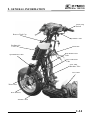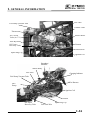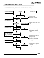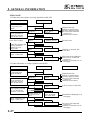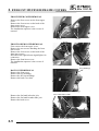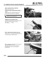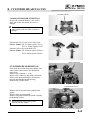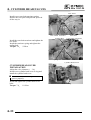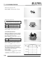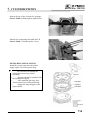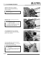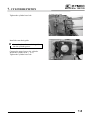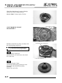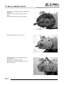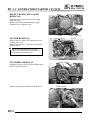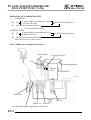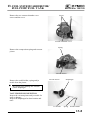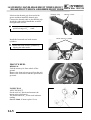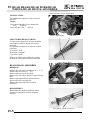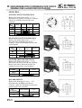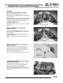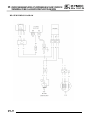
1
Bet & Win 125/150
PREFACE
TABLE OF CONTENTS
This Service Manual describes the
technical features and servicing
procedures for the KYMCO Bet & Win
125/150.
Section 1 contains the precautions for
all operations stated in this manual.
Read them carefully before any
operation is started.
ENGINE
Section 2 is the removal/installation
procedures for the frame covers which
are subject to higher removal/installation
frequency during maintenance and
servicing operations.
Section 3 describes the inspection/
adjustment procedures, safety rules and
service information for each part, starting
from periodic maintenance.
Most sections start with an assembly or
system illustration and troubleshooting
for the section. The subsequent pages
give detailed procedures for the section.
KWANG YANG MOTOR CO., LTD.
OVERSEAS SALES DEPARTMENT
OVERSEAS SERVICE SECTION
EQUIPMENT
The information and contents included in
this manual may be different from the
motorcycle in case specifications are
changed.
1
EXHAUST MUFFLER/FRAME COVERS
2
INSPECTION/ADJUSTMENT
3
LUBRICATION SYSTEM
4
ENGINE REMOVAL/INSTALLATION
5
CYLINDER HEAD/VALVES
6
CYLINDER/PISTON
7
DRIVE AND DRIVEN PULLEYS/KICK
STARTER
8
FINAL REDUCTION
9
A.C. GENERATOR/STARTER CLUTCH 10
CHASSIS
Sections 5 through 13 give instructions
for disassembly, assembly and adjustment
of engine parts. Section 14 is the
removal/ installation of chassis. Section
16 states the testing and measuring
methods of electrical equipment.
GENERAL INFORMATION
CRANKCASE/CRANKSHAFT
11
COOLING SYSTEM
12
FUEL SYSTEM/CARBURETOR/FUEL
PUMP FUEL TANK
13
STEERING HANDLEBAR/FRONT
WHEEL/FRONT BRAKE/FRONT
SHOCK ABSORBER/FRONT FORK
14
REAR BRAKE/REAR FORK/REAR
WHEEL/REAR SHOCK ABSORBER`
15
BATTERY/CHARGING SYSTEM
16
IGNITION SYSTEM
17
STARTING SYSTEM
18
SWITCHES/HORN/FUEL UNIT /
T HERMO-STATIC
SWITCH/TEMPERATURE
GAUGE/INSTRUMENTS/ LIGHTS
19
1. GENERAL INFORMATION
Bet & Win 125/150
1
1
__________________________________________________________________________________
__________________________________________________________________________________
__________________________________________________________________________________
__________________________________________________________________________________
__________________________________________________________________________________
GENERAL INFORMATION
__________________________________________________________________________________
ENGINE SERIAL NUMBER--------------------------------------------- 1-1
SPECIFICATION---------------------------------------------------------- 1-2
SERVICE PRECAUTIONS----------------------------------------------- 1-4
TORQUE VALUES ------------------------------------------------------- 1-8
TOOLS --------------------------------------------------------------------- 1-9
LUBRICATION POINTS------------------------------------------------1-10
CABLE & HARNESS ROUTING-----------------------------------------1-12
WIRING DIAGRAM-------------------------------------------------------------------1-17
TROUBLESHOOTING --------------------------------------------------1-18
1-0
1. GENERAL INFORMATION
Bet & Win 125/150
SERIAL NUMBER
Vehicle Identification Serial Number
Location of Frame Serial Number
1-1
Location of Engine Serial Number
1. GENERAL INFORMATION
Bet & Win 125/150
SPECIFICATIONS
Displacement
Fuel Used
0°
0.1
0.1
1500rpm
Forced pressure &
wet sump
Inner/outer rotor
type
Full-flow filtration
1.1 liters
Spark plug gap
Battery Capacity
Clutch Type
NGK
DPR7EA-9
0.9mm
12V8AH
Dry multi-disc clutch
Type
Non-stage transmission
Operation
Automatic
centrifugal
Type
Reduction
Gear
8.4/8250
9.9/6500
BTDC 12°
ATDC 35°
BDDC 28°
Spark plug
Transmission Gear
Oil filter type
Oil capacity
15
Air cleaner type & No Paper element, wet
Fuel capacity
10.6 liters
Type
VE
Piston dia.
22
Venturi dia.
26 equivalent
Throttle type
Butterfly type
Type
CDI
Ignition timing
BTDC 10°±1°
Contact breaker Non-contact point
type
Ignition System
Oil pump type
2300mm
Starting motor &
Kick starter
Gasoline, 4-stroke
Single cylinder
Semi-sphere
O.H.C.
52.4 x 57.8
10.6:1
Type
Two-stage reduction
Reduction 1st
ratio
2nd
Front Caster angle
Axle Connecting rod
Front
Tire pressure
(kg/cm_)
Rear
Turning
Left
angle
Right
Front
Brake system
type
Rear
Front
Suspension
type
Rear
Shock absorber Front
type
Rear
Frame type
Damping
Device
System
Lubrication type
54
75
129
58.5
79.5
138
120/70-12 56J
130/70-12 59J
155mm
30km/hr4.4m
Moving Device
Engine
Type
Cylinder arrangement
Combustion chamber type
Valve arrangement
Bore x stroke (mm)
Compression ratio
Compression pressure
(kg/cm_-rpm)
Max. output (kw/rpm)
Max. torque (N.m/rpm)
Intake
Open
Port (1mm) Close
timin Exhaust Open
g
(1mm) Close
Intake
Valve
clearance (cold) Exhaust
Idle speed (rpm)
124cc
92# nonleaded gasoline
Power Drive System
Starting system
OHC engine
Electrical
Front wheel
Net weight (kg) Rear wheel
Total
Front wheel
Gross weight(kg) Rear wheel
Total
Front wheel
Tires
Rear wheel
Ground clearance
Perform Braking distance (m)
ance
Min. turning radius
1940mm
750mm
1145mm
1390mm
Water cooled 4-stroke,
Carburetor
Engine type
Water cooling
SH25CA
Fuel System
Name & Model No.
Motorcycle Name & Type
Overall length
Overall width
Overall height
Wheel base
Cooling Type
2.8~1.0
8.82
2.00
2.25
42.5°
42.5°
Disk brake
Disk brake
Telescope
Double swing
Telescope
Double swing
Under bone
1-2
1. GENERAL INFORMATION
Bet & Win 125/150
SPECIFICATIONS
Displacement
Fuel Used
0°
0.1
0.1
1500rpm
Forced pressure &
wet sump
Inner/outer rotor
type
Full-flow filtration
1.1 liters
Spark plug gap
Battery Capacity
Clutch Type
NGK
DP7EA-9
0.9mm
12V8AH
Dry multi-disc clutch
Type
Non-stage transmission
Operation
Automatic
centrifugal
Type
Reduction
Gear
1-3
9.1/7500
11.6/6500
BTDC 12°
ATDC 35°
BDDC 28°
Spark plug
Transmission Gear
Oil filter type
Oil capacity
15
Air cleaner type & No Paper element, wet
Fuel capacity
10.6 liters
Type
VE
Piston dia.
22
Venturi dia.
26 equivalent
Throttle type
Butterfly type
Type
CDI
Ignition timing
BTDC 10°±1°
Contact breaker Non-contact point
type
Ignition System
Oil pump type
2300mm
Starting motor &
kick starter
Gasoline, 4-stroke
Single cylinder
Semi-sphere
O.H.C.
57.4 x 57.8
10.6:1
Type
Two-stage reduction
Reduction 1st
ratio
2nd
Front Caster angle
Axle Connecting rod
Front
Tire pressure
(kg/cm_)
Rear
Turning
Left
angle
Right
Front
Brake system
type
Rear
Front
Suspension
type
Rear
Shock absorber Front
type
Rear
Frame type
Damping
Device
System
Lubrication type
54
75
129
58.5
79.5
138
120/70-12 56J
130/70-12 59J
155mm
30km/hr4.4m
Moving Device
Engine
Type
Cylinder arrangement
Combustion chamber type
Valve arrangement
Bore x stroke (mm)
Compression ratio
Compression pressure
(kg/cm_-rpm)
Max. output (kw/rpm)
Max. torque (N.m/rpm)
Intake
Open
Port (1mm) Close
timin Exhaust Open
g
(1mm) Close
Intake
Valve
clearance (cold) Exhaust
Idle speed (rpm)
150cc
92# nonleaded gasoline
Power Drive System
Starting system
OHC engine
Electrical
Front wheel
Net weight (kg) Rear wheel
Total
Front wheel
Gross weight(kg) Rear wheel
Total
Front wheel
Tires
Rear wheel
Ground clearance
Perform Braking distance (m)
ance
Min. turning radius
1940mm
750mm
1145mm
1390mm
Water cooled 4-stroke,
Carburetor
Engine type
Water cooling
SH30CA
Fuel System
Name & Model No.
Motorcycle Name & Type
Overall length
Overall width
Overall height
Wheel base
Cooling Type
2.8~1.0
8.82
2.00
2.25
42.5°
42.5°
Disk brake
Disk brake
Telescope
Double swing
Telescope
Double swing
Under bone
1. GENERAL INFORMATION
SERVICE PRECAUTIONS
n Make sure to install new gaskets, O-rings,
circlips, cotter pins, etc. when
reassembling.
Bet & Win 125/150
n Apply or add designated greases and
lubricants to the specified lubrication
points.
n After reassembly, check all parts for
proper tightening and operation.
n When tightening bolts or nuts, begin with
larger-diameter to smaller ones at several
times, and tighten to the specified torque
diagonally.
n When two persons work together, pay
attention to the mutual working safety.
n Use genuine parts and lubricants.
n Disconnect the battery negative (-) terminal
before operation.
n When using a spanner or other tools, make
sure not to damage the motorcycle surface.
n When servicing the motorcycle, be sure to
use special tools for removal and
installation.
n After disassembly, clean removed parts.
Lubricate sliding surfaces with engine oil
before reassembly.
n After operation, check all connecting
points, fasteners, and lines for proper
connection and installation.
n When connecting the battery, the positive
(+) terminal must be connected first.
n After connection, apply grease to the
battery terminals.
n Terminal caps shall be installed securely.
1-4
1. GENERAL INFORMATION
n If the fuse is burned out, find the cause and
repair it. Replace it with a new one
according to the specified capacity.
Confirm
Capacity
Bet & Win 125/150
n The connector shall be inserted
completely.
n If the double connector has a lock, lock
it at the correct position.
n Check if there is any loose wire.
n After operation, terminal caps shall be
installed securely.
n Before connecting a terminal, check for
damaged terminal cover or loose negative
terminal.
n When taking out the connector, the lock on
the connector shall be released before
operation.
n Check the double connector cover for
proper coverage and installation.
n Hold the connector body when connecting
or disconnecting it.
n Do not pull the connector wire.
n Insert the terminal completely.
n Check the terminal cover for proper
coverage.
n Do not make the terminal cover opening
face up.
n Check if any connector terminal is bending,
protruding or loose.
1-5
n Secure wire harnesses to the frame with
their respective wire bands at the
designated locations.
Tighten the bands so that only the
insulated surfaces contact the wire
harnesses.
1. GENERAL INFORMATION
n After clamping, check each wire to make
sure it is secure.
Bet & Win 125/150
n Route harnesses so they are neither
pulled tight nor have excessive slack.
Do not pull
too tightð
n Do not squeeze wires against the weld or
its clamp.
n Protect wires and harnesses with electrical
tape or tube if they contact a sharp edge or
corner.
n After clamping, check each harness to make
sure that it is not interfering with any
moving or sliding parts.
n When rubber protecting cover is used to
protect the wire harnesses, it shall be
installed securely.
n When fixing the wire harnesses, do not
make it contact the parts which will
generate high heat.
No Contact
n Route wire harnesses to avoid sharp edges
or corners. Avoid the projected ends of
bolts and screws.
n Route wire harnesses passing through the
side of bolts and screws. Avoid the
projected ends of bolts and screws.
n Do not break the sheath of wire.
n If a wire or harness is with a broken sheath,
repair by wrapping it with protective tape
or replace it.
n When installing other parts, do not press or
squeeze the wires.
Do not press
or squeeze the
wire
1-6
1. GENERAL INFORMATION
n After routing, check that the wire harnesses
are not twisted or kinked.
n Wire harnesses routed along with handlebar
should not be pulled tight, have excessive
slack or interfere with adjacent or
surrounding parts in all steering positions.
Bet & Win 125/150
n Symbols:
The following symbols represent the
servicing methods and cautions included in
this service manual.
Engine Oil
Grease
Gear Oil
n When a testing device is used, make sure to
understand the operating methods
thoroughly and operate according to the
operating instructions.
Do you
understand the
instrument?
Special
*
: Apply engine oil to the
specified points. (Use
designated engine oil for
lubrication.)
: Apply grease for lubrication.
: Transmission Gear Oil (90#)
: Use special tool.
: Caution
: Warning
n Be careful not to drop any parts.
n When rust is found on a terminal, remove
the rust with sand paper or equivalent
before connecting.
Remove
Rustð
1-7
1. GENERAL INFORMATION
Bet & Win 125/150
TORQUE VALUES
STANDARD TORQUE VALUES
Item
5mm bolt, nut
6mm bolt, nut
8mm bolt, nut
10mm bolt, nut
12mm bolt, nut
Torque (N-m)
4.9
9.8
21.6
34.3
53.9
Item
5mm screw
6mm screw, SH bolt
6mm flange bolt, nut
8mm flange bolt, nut
10mm flange bolt, nut
Torque (N-m)
3.9
8.8
11.8
26.5
39.2
Torque specifications listed below are for important fasteners.
ENGINE
Item
Cylinder head bolt A
Cylinder head bolt B
Oil filter screen cap
Exhaust muffler joint lock nut
Cylinder head cap nut
Valve adjusting lock nut
Cam chain tensioner slipper bolt
Oil bolt
Clutch outer nut
Clutch drive plate nut
Flywheel nut
Oil pump bolt
Cylinder head cover bolt
Spark plug
Cam chain tensioner bolt
Water pump impeller
Q‘ty Thread dia.(mm)
2
2
1
2
4
2
1
1
1
1
1
2
4
1
1
1
8
8
30
8
8
5
6
12
12
12
14
5
6
10
6
8
Torque (N-m)
21.6
21.6
14.7
8.8
21.6
8.8
8.8
12.7
53.9
53.9
53.9
3.9
11.8
11.8
8.8
13.7
Remarks
Double end bolt
Double end bolt
Apply oil to
threads
Left hand threads
FRAME
Item
Steering stem lock nut
Front axle nut
Rear axle nut
Rear shock absorber upper bolt
Rear shock absorber lower bolt
Front shock absorber lock bolt
Engine hanger bolt
Q‘ty Thread dia.(mm)
1
1
1
2
2
4
1
10
12
14
10
8
10
12
Torque (N-m)
Remarks
44.1
58.8
88.2
29.4
29.4
24.5
53.9
U-nut
U-nut
U-nut
1-8
1. GENERAL INFORMATION
Bet & Win 125/150
SPECIAL TOOLS
Tool Name
Valve guide driver
Valve guide reamer
Valve spring compressor
Lock nut wrench, 39mm
Bearing driver
Bearing remover, 12mm
Remover shaft
Remover weight
Bearing remover, 15mm
Bearing driver
Clutch spring compressor
Ball race remover extension
Ball race remover
Spring compressor
Mechanical seal driver
Kick starter spring remover
Gear remover
Valve adjuster
Float level gauge
Valve seat cutter 45°
Valve seat cutter 32°
Valve seat cutter 60°
Cutter clip, 5mm
Universal holder
Bearing driver (32x35mm)
Pilot, 12mm
Pilot, 15mm
Pilot, 17mm
Flywheel puller
Rear shock absorber compressor
Steering head bearing remover
Flywheel holder
Reamer clip
Fuel unit wrench
1-9
Tool No.
E027
E020
E018
E027
E014
E012
E017
E014
E014
E014
E014
E003
F004
F005
E021
Remarks
Valve guide removal/installation
Valve guide grinding
Valve removal
Clutch disassembly
Bearing removal
Bearing removal
Bearing removal
Bearing removal
Bearing removal
Bearing removal
Clutch disassembly
Ball race removal
Ball race removal
Spring removal
Water pump mechanical seal
removal/installation
Kick starter spring removal
Starter gear removal
Tapper adjustment
Carburetor fuel level check
Valve seat refacing
Valve seat refacing
Valve seat refacing
Holding clutch for removal
Bearing installation
Bearing installation
Bearing installation
Bearing installation
A.C. generator flywheel removal
Rear shock absorber disassembly
Steering head bearing removal
A.C. generator flywheel holding
Fuel unit removal
Ref. Page
1. GENERAL INFORMATION
Bet & Win 125/150
LUBRICATION POINTS
ENGINE
Lubrication Points
Valve guide/valve stem movable part
Camshaft protruding surface
Valve rocker arm friction surface
Camshaft drive chain
Cylinder lock bolt and nut
Piston surroundings and piston ring grooves
Piston pin surroundings
Cylinder inside wall
Connecting rod/piston pin hole
Connecting rod big end
Crankshaft
Cranksahft one-way clutch movable part
Oil pump drive chain
Starter reduction gear engaging part
Countershaft gear engaging part
Final gear engaging part
Bearing movable part
O-ring face
Oil seal lip
Starter idle gear
Friction spring movable part/shaft movable part
Shaft movable grooved part
Starter spindle movable part
Lubricant
•Genuine KYM CO Engine Oil (SAE15W-40)
•API SE, SF or SG Egnine Oil
High-temperature resistant grease
Starter one-way clutch threads
Thread locking agent
A.C. generator connector
Transmission case breather tubee
Adhesive
1-10
1. GENERAL INFORMATION
Bet & Win 125/150
FRAME
The following is the lubrication points for the frame.
Use general purpose grease for parts not listed.
Apply clean engine oil or grease to cables and movable parts not specified. This will avoid
abnormal noise and rise the durability of the motorcycle.
Grease
Engine Oil
Speedometer Cable
Throttle Cable
Grease
Seat Lock
Speedometer Gear/
Front Wheel Bearing
Grease
1-11
Front Brake Lever Pivot
Rear Wheel Bearing
Grease
1. GENERAL INFORMATION
Bet & Win 125/150
CABLE & HARNESS ROUTING
Front Brake Fluid Tube
Front Stop Switch
Rear Brake Fluid Tube
Rear Stop Switch
Throttle Cable
Speedometer Cable
Pressure
Type
Radiator Cap
Radiator Air
Vent Tube
Radiator
Horn
1-12
1. GENERAL INFORMATION
Bet & Win 125/150
Ignition Switch
Radiator Air
Vent Tube
Fuel Tank
Breather Tube
Fuel Filler
Thermostatic
Switch
Fuel Tank
Inlet Tube
Water Hose
Fuel Pump
Water Hoses
1-13
Front Brake Fluid Tube
1. GENERAL INFORMATION
Bet & Win 125/150
Front Stop
Switch
Reserve Tank Cap
Throttle Cable
Radiator Air
Vent Tube
Speedometer Cable
Fuel Filler
Rear Brake Fluid
Tube
Fuel Tank Inlet
Tube
Fuel Tank
Breather Tube
Fuel Tank
Water Hose
Wire Harness
Throttle Cable
1-14
1. GENERAL INFORMATION
Oil Vapor
Recovery Tube
Auto Bystarter Wire
Bet & Win 125/150
Fuel Tube
Thermostat
Ignition Coil
Carburetor
Starter Motor
Charging Indicator
Air Cut-off
Valve (A.C.V.)
Starter Relay
Regulator/
Rectifier
Battery (+) Cable
Fuse Box
Battery (-) Cable
1-15
1. GENERAL INFORMATION
Bet & Win 125/150
Fuel Tube
Fuel Pump Vacuum Tube
Throttle Cable
Thermostat
Air Cut-off
Valve (A.C.V.)
Starter Motor
Auto Bystarter
Oil Vapor
Recovery Tube
Vacuum
Ground Wire
Spark Plug Cap
Ignition Coil
Regulator/
Rectifier
Starter Relay
Fuel Tube
Charging Indicator
Fuel Pump Vacuum Tube
Wire Harness
Fuel
Pump
Ignition Coil
Vacuum
Oil Vapor
Recovery Tube
Fuel Unit Wire
Spark Plug Cap
1-16
1. GENERAL INFORMATION
WIRING DIAGRAM
1-17
Bet & Win 125/150
1. GENERAL INFORMATION
Bet & Win 125/150
TROUBLESHOOTING
ENGINE WILL NOT START OR IS HARD TO START
Inspection/Adjustment
Symptom
Check if fuel reaches
carburetor by
loosening drain screw
Fuel reaches
carburetor
Fuel does not
reach carburetor
ÅEmpty fuel tank
ÇClogged carburetor fuel inlet
tube, vacuum tube or fuel tube
ÉClogged auto fuel valve
ÑClogged float oil passage
ÖClogged fuel tank cap
breather hole
ÜClogged fuel strainer
áClogged fuel filter
àFaulty fuel pump
Weak or no spark
ÅFaulty spark plug
ÇFouled spark plug
ÉFaulty CDI unit
ÑFaulty A.C. generator
ÖBroken or shorted ignition coil
ÜBroken or shorted exciter
coil
áFaulty ignition switch
Low or no
compression
ÅStarter motor idles but
crankshaft does not rotate
ÇValve clearance too small
ÉImproper valve and seat
contact
ÑWorn cylinder and piston rings
ÖBlown cylinder head gasket
ÜFlaws in cylinder head
áSeized valve
àImproper valve timing
Remove spark plug
and install it into
spark plug cap to test
spark by connecting it
to engine ground
Spark jumps
Test cylinder
compression
Normal
compression
Probable Cause
Start engine by following normal starting
procedure
Engine does not
fire
Engine fires but
does not start
Dry spark plug
Wet spark plug
ÅFaulty auto bystarter
ÇAir leaking through intake
pipe
ÉIncorrect ignition timing
ÑIncorrectly adjusted pilot
screw
Remove spark plug and
inspect again
ÅFlooded carburetor
ÇFaulty auto bystarter
ÉThrottle valve excessively
open
1-18
1. GENERAL INFORMATION
Bet & Win 125/150
ENGINE LACKS POWER
Inspection/Adjustment
Symptom
Probable Cause
Start engine and accelerate
lightly for observation
Engine speed
increases
Check ignition timing
(using a timing light)
Engine speed does
not increase
sufficiently
Correct timing
Incorrect timing
Correct
Incorrect
ÅClogged air cleaner
ÇRestricted fuel flow
ÉClogged fuel line between fuel
tank and carburetor
ÑClogged exhaust muffler
ÖFaulty auto bystarter
ÜSplit carburetor vacuum piston
diaphragm
ÅFaulty CDI unit
ÇFaulty A.C. generator
Check valve clearance
Test cylinder compression
Normal
compression
Abnormal
compression
Check carburetor for
clogging
Not Clogged
Clogged
ÅImproper valve clearance
adjustment
ÇWorn valve seat (valve stem too
protruding
ÅImproper valve and seat contact
ÇWorn cylinder and piston rings
ÉBlown cylinder head gasket
ÑFlaws in cylinder head
ÖImproper valve timing
ÅClogged carburetor jets
Remove spark plug and
inspect
Plug not fouled or
discolored
Plug fouled or
discolored
ÅFouled spark plug
ÇIncorrect heat range plug
Correct and not
contaminated
Incorrect or
contaminated
ÅOil level too high
ÇOil level too low
ÉOil not changed
Valve train not
lubricated properly
ÅClogged oil pipe
ÇFaulty oil pump
Remove oil dipstick and
check oil level and condition
Remove cylinder head oil
pipe bolt and inspect
Valve train lubricated
properly
Check if engine overheats
Engine does not
overheats
Engine overheats
Rapidly accelerate or run
at high speed
Engine does not knock
1-19
Engine knocks
ÅInsufficient coolant
ÇFaulty thermostat
ÉWorn cylinder and piston rings
ÑMixture too lean
ÖPoor quality fuel
ÜExcessive carbon buildup in
combustion chamber
áIgnition timing too early
àAir in cooling system
ÅExcessive carbon build-up in
combustion chamber
ÇPoor quality fuel
ÉClutch slipping
ÑMixture too lean
Ö Ignition timing too early
1. GENERAL INFORMATION
Bet & Win 125/150
POOR PERFORMANCE (ESPECIALLY AT IDLE AND LOW SPEEDS)
Inspection/Adjustment
Symptom
Probable Cause
Check ignition timing
Correct timing
Incorrect timing
Correctly adjusted
Incorrectly adjusted
ÅFaulty CDI unit
ÇFaulty A.C. generator
Check carburetor pilot
screw adjustment
ÅMixture too rich (turn screw
out)
ÇMixture too lean (turn screw
in)
Check carburetor
gasket for air leaks
No air leak
Air leaks
Remove spark plug
and install it into
spark plug cap to test
spark by connecting it
to engine ground
ÅDamaged insulator rubber
ÇCarburetor not securely
tightened
ÉFaulty intake manifold
gasket
ÑDeformed carburetor O-ring
Good spark
Weak or intermittent spark
ÅFaulty or fouled spark plug
ÇFaulty CDI unit
ÉFaulty A.C. generator
ÑFaulty ignition coil
ÖBroken or shorted high
tension wire
ÜFaulty ignition switch
Good
Faulty
ÅDamaged air cut-off valve
diaphragm
ÇDamaged air cut-off valve
spring
Check carburetor air
cut-off valve
1-20
1. GENERAL INFORMATION
Bet & Win 125/150
POOR PERFORMANCE (AT HIGH SPEED)
Inspection/Adjustment
Symptom
Probable Cause
Check ignition timing
ÅFaulty CDI unit
ÇFaulty A.C. generator
Correct timing
Incorrect timing
Correctly adjusted
Incorrectly adjusted
ÅImproperly adjusted valve
clearance
ÇWorn valve seat
Fuel flow restricted
ÅEmpty fuel tank
ÇClogged fuel tube or filter
ÉFaulty fuel pump
ÑCracked fuel pump vacuum
Check valve clearance
Check fuel pump for
fuel supply
Fuel flows freely
tube
Check carburetor jets
for clogging
Not clogged
Clogged
Correct
Incorrect
Not weakened
Weak spring
ÅClean and unclog
Check valve timing
ÅCam timing gear aligning
marks not aligned
Check valve spring
tension
1-21
ÅFaulty spring
1. GENERAL INFORMATION
Bet & Win 125/150
ENGINE NOISE
Symptom
Valve noise
Probable Cause
ÅValve clearance too large
ÇWorn camshaft lobe
ÅWorn piston rings
Piston noise
Cam chain noise
Crankshaft noise
ÇWorn piston pin and connecting rod
small end
ÉExcessive carbon build-up in combustion
chamber
ÅDamaged cam chain tensioner
ÇWorn cam gear teeth
ÉWorn or damaged cam chain
ÑExtended cam chain
ÅFaulty crankshaft bearing
ÇWorn crank pin bearing
Gear noise
ÅWorn or damaged final reduction gears
ÇWorn final reduction gear shaft splines
1-22
1. GENERAL INFORMATION
Bet & Win 125/150
CLUTCH, DRIVE AND DRIVEN PULLEYS
Symptom
Engine starts but
motor-cycle does not
move
Motorcycle creeps or
engine starts but soon
stops or seems to rush
out (Rear wheel
rotates when engine
idles)
1-23
Probable Cause
ÅWorn or slipping drive belt
ÇBroken ramp plate
ÉBroken drive face spring
ÑSeparated clutch lining
ÖDamaged driven pulley shaft splines
ÜDamaged final gear
áSeized final gear
ÅBroken shoe spring
ÇClutch outer and clutch weight stuck
ÉSeized pivot
Engine lacks power at
start of a grade(poor
slope performance)
ÅWorn or slipping drive belt
ÇWorn weight rollers
ÉSeized drive pulley bearings
ÑWeak driven face spring
ÖWorn or seized driven pulley bearings
Engine lacks power at
high speed
ÅWorn or slipping drive belt
ÇWorn weight rollers
ÉWorn or seized driven pulley bearings
There is abnormal
noise
or smell while running
ÅOil or grease fouled drive belt
ÇWorn drive belt
ÉWeak driven face spring
ÑWorn or seized driven pulley bearings
1. GENERAL INFORMATION
Bet & Win 125/150
STARTER MOTOR
1. Starter motor won‘t turn
Symptom
Inspection/Adjustment
Probable Cause
Check operation of
stop switch by
applying brake
Check battery
circuit by operating
turn signals
Check operation of
starter relay by
depressing starter
button
Stoplight comes
on
Stoplight does not
come on
Signals operate
properly
Signals dim, remain
on or don‘t
operate
Relay operates
properly
Relay does not
operate
Connect starter
motor directly to
battery
ÅBurned out fuse
ÇWeak or dead battery
ÉFaulty stop switch
ÑLoose or disconnected
connectors
ÖBroken or shorted ignition
switch wire
ÅFaulty or weak battery
ÅPoor starter button
connection
ÇOpen or shorted starter relay
ÉLoose or disconnected
connectors
Starter motor
turns
Starter does not
turn
ÅOpen wire harness
2. Starter motor turns slowly or idles
Symptom
Inspection/Adjustment
ÅWorn brushes
ÇOpen or shorted wires or
rotor
ÉOpen starter motor cable
ÑLoose connectors
Probable Cause
Check battery
circuit by operating
turn signals
Connect starter
motor directly to
battery
Signals operate
properly
Signals dim, remain
on or don‘t operate
Starter motor
turns slowly
Starter motor
turns normally
Turns easily
Hard to turn
ÅWeak or dead battery
ÅLoose connector or terminal
ÇPoor contact in starter relay
ÉFaulty starter clutch
Rotate crankshaft
ÅBroken or shorted starter
motor cable
3. Starter motor does not stop turning
Symptom
Inspection/Adjustment
Turn ignition
switch
OFF
Not stopped
ÅSeized cylinder
Probable Cause
Stopped
ÅFaulty starter pinion
ÅStarter relay shorted or stuck
1-24
1. GENERAL INFORMATION
Bet & Win 125/150
closed
NO SPARK AT SPARK PLUG
Inspection/Adjustment
Symptom
Probable Cause
Replace with a new
spark plug and inspect
again
Weak or no spark
Good spark
ÅFaulty spark plug
Not loose
Loose
ÅFaulty spark plug
Good
Good
ÅPoorly connected coupler
Normal
Abnormal
Normal
Abnormal
Check spark plug cap
and high-tension wire
for looseness
Check CDI unit
coupler for looseness
Measure resistance
between terminals of
CDI unit coupler
Check related parts
ÅFaulty ignition switch
ÇFaulty exciter coil
ÉFaulty pulser coil
ÑFaulty ignition coil
ÅBroken wire harness
ÇPoorly connected coupler
Check CDI unit with a
CDI unit tester
Normal
Abnormal
ÅFaulty CDI unit
Check ignition coil
with a CDI unit tester
Abnormal
1-25
ÅFaulty ignition coil
1. GENERAL INFORMATION
Bet & Win 125/150
POOR CHARGING (BATTERY OVER DISCHARGING OR OVERCHARGING)
Undercharging
Inspection/Adjustment
Symptom
Probable Cause
Start engine and test
limit voltage of
battery terminals
Normal voltage
Voltage does not
increase
Normal
Resistance too
low
ÅFaulty AC generator
ÇFaulty regulator/rectifier
ÉFaulty battery
Measure resistance
between AC generator
coil terminals
ÅShorted AC generator coil
ÇOpen circuit between AC
generator 3 yellow wires
Test output voltage of
regulator/rectifier
coupler red wire
Normal voltage
No voltage
ÅFaulty regulator/rectifier
ÇFaulty AC generator
ÉLoose regulator/rectifier
coupler
ÑLimit voltage too high
Overcharging
Inspection/Adjustment
Symptom
Probable Cause
Measure battery limit
voltage with an
electric tester
Normal
Abnormal
ÅFaulty battery
ÇFaulty regulator/rectifier
ÉBroken or poorly
connected
regulator/rectifier black wire
Check resistance
between regulator/
rectifier terminals
Normal
Abnormal
ÅLimit voltage too high
1-26
1. GENERAL INFORMATION
Bet & Win 125/150
FUEL GAUGE
1. Pointer does not register correctly (Ignition switch ON)
Inspection/Adjustment
Symptom
Probable Cause
Check battery circuit
by operating turn
signals
Remove fuel unit and
check operation of
pointer by moving
float up and down
Float up: Full
Float down: Empty
Check operation of
pointer by opening and
shorting fuel unit
terminal on wire
harness side
Signals operate
properly
Signals dim, remain
on or don‘t
operate
Pointer does not
move
Pointer does not
move
Pointer moves
ÅFaulty float
Pointer moves
ÅBroken or shorted fuel
unit wire
Check connectors for
proper connection
Faulty
Good
2. Pointer fluctuates or swings (Ignition switch ON)
Inspection/Adjustment
Symptom
Remove fuel unit and
check operation of
pointer by moving
float up and down
Pointer moves
Move float up and
down rapidly (1 round
/sec.) to check the
operation of pointer
Pointer moves in
accordance with
float
ÅDisconnected connector
ÇIncorrectly connected
connector
ÉBroken or shorted wire in
fuel gauge
Probable Cause
Check battery circuit
by operating turn
signals and horn
Signals operate
properly
ÅBurned out fuse
ÇWeak or dead battery
ÉFaulty ignition switch
ÑLoose or disconnected
connectors
ÖBroken wire harness
Signals dim,
remain
on or don‘t
operate
Pointer does not
move
Pointer does not
move in accordance with float
ÅBurned out fuse
ÇWeak or dead battery
ÉFaulty ignition switch
ÑLoose or disconnected
connector
ÖBroken wire harness
ÅPoor contact in fuel unit
ÅInsufficient damping oil in
fuel gauge
Check connectors for
proper connection.
Good
1-27
Faulty
ÅLoose or disconnected
connector
ÅBroken or shorted wire in
fuel gauge
1. GENERAL INFORMATION
Bet & Win 125/150
STEERING HANDLEBAR DOES NOT TRACK STRAIGHT
Symptom
Probable Cause
(Front and rear tire pressures are normal)
Steering is heavy
ÅSteering stem nut too tight
ÇBroken steering steel balls
Front or rear wheel is
wobbling
ÅExcessive wheel bearing play
ÇBent rim
ÉLoose axle nut
Steering handlebar pulls
to one side
ÅMisaligned front and rear wheels
ÇBent front fork
POOR SUSPENSION PERFORMANCE
Symptom
Suspension is too soft
Probable Cause
(Front and rear tire pressures are normal)
ÅWeak shock spring
ÇExcessive load
ÉShock damper oil leaking
Suspension is too hard
ÅBent fork tube or shock rod
Suspension is noisy
ÅFork tube and slider binding
ÇFork spring and slider binding
ÉDamaged shock stopper rubber
ÑLoose steering stem nut
POOR BRAKE PERFORMANCE
Symptom
Probable Cause
Soft brake lever
ÅWorn brake linings
ÇForeign matter on brake linings
ÉRough brake drum contacting area
Hard brake lever
ÅWorn brake linings
ÇForeign matter on brake linings
ÉRough brake drum contacting area
Hard to brake
ÅWorn brake linings
ÇWorn brake cam contacting area on
Poor brake
performance
Brake squeaks
ÅWorn brake linings
ÇForeign matter on brake linings
ÅSluggish or elongated brake cables
ÇBrake shoes improperly contact
ÉWater and mud in brake system
ÑOil or grease on brake linings
1-28
2. EXHAUST MUFFLER/FRAME COVERS
Bet & Win 125/150
2
__________________________________________________________________________________
2
__________________________________________________________________________________
__________________________________________________________________________________
__________________________________________________________________________________
__________________________________________________________________________________
EXHAUST MUFFLER/FRAME COVERS
__________________________________________________________________________________
SCHEMATIC DRAWING ---------------------------------------------- 2-1
SERVICE INFORMATION -------------------------------------------- 2-2
TROUBLESHOOTING ------------------------------------------------- 2-2
FRAME COVERS REMOVAL----------------------------------------- 2-3
EXHAUST MUFFLER REMOVAL ----------------------------------- 2-6
2-0
2. EXHAUST MUFFLER/FRAME COVERS
SCHEMATIC DRAWING
2-1
Bet & Win 125/150
2. EXHAUST MUFFLER/FRAME COVERS
Bet & Win 125/150
SERVICE INFORMATION
GENERAL INSTRUCTIONS
• When removing frame covers, use care not to pull them by force because the cover joint claws
may be damaged.
• Make sure to route cables and harnesses according to the Cable & Harness Routing.
TORQUE VALUES
Exhaust muffler lock bolt
Exhaust muffler joint lock nut
34.3N-m
11.8N-m
TROUBLESHOOTING
Noisy exhaust muffler
• Damaged exhaust muffler
• Exhaust muffler joint air leaks
Lack of power
• Caved exhaust muffler
• Clogged exhaust muffler
• Exhaust muffler air leaks
2-2
2. EXHAUST MUFFLER/FRAME COVERS
Bet & Win 125/150
Bolts/Nuts
FRAME COVERS REMOVAL
REAR CARRIER & HAND RAIL
REMOVAL
Remove the met-in box:
First remove the two bolts and two nuts
attaching the met-in box.
Remove the battery, C D I, fuse.
Remove the met-in box.
Fuse
Hex Bolts
Remove the hand rail right and left lock hex
bolts.
Remove the four hex bolts
Remove the rear carrier and hand rail.
Hex Bolts
FRAME BODY COVER REMOVAL
Remove the one screws on the bottom of the
center cover.
Remove the center cover.
Remove the two screws attaching the front
part of the frame body cover.
Center Cover
Frame Body Cover
Screws
Screws
Remove the right and left screws on the rear
part of the frame body cover.
Disconnect the seat lock wire.
Remove the frame body cover.
Screws
2-3
2. EXHAUST MUFFLER/FRAME COVERS
Bet & Win 125/150
Remove the midst screw attaching the right
and left side covers.
Screws
Side Cover
Remove the screws attaching the right and left
side covers.
Screw
Screws
FLOOR BOARD REMOVAL
Remove the floor mat.
Remove the center cover. (!2-3)
Remove the five screws and four screws
attaching the front right and left side covers.
Remove the two bottom cover adjusting
screws.
Remove the front right and left side covers.
Screw
Nuts
Adjusting Screws
Prop
Screw
Remove the air box four screws.
Remove the prop two bolts.
Remove the two nuts
Remove the six bolts attaching the floor
board.
Remove the floor board .
The installation sequence is the reverse of
removal.
Floor Board
Bolts
2-4
2. EXHAUST MUFFLER/FRAME COVERS
Bet & Win 125/150
FRONT UPPER COVER REMOVAL
Remove the four screws on the front upper
cover.
Remove the four screws on the back of the
front upper cover.
Remove the front upper cover.
The installation sequence is the reverse of
removal.
Screws
FRONT LOWER COVER REMOVAL
First remove the front upper cover.
Remove the two screws attaching the front
lower cover.
Remove the four screws on the back of the
front lower cover.
Disconnect the right/left turn signal light wire
connectors.
Remove the front lower cover
The installation sequence is the reverse of
removal.
Screws
Screws
Screws
Key Moldings
BACK COVER REMOVAL
Remove the front cover.
Remove the key moldings.
Remove the fuel cap moldings.
Remove the back cover bolt.
Bolt
Remove the fuel tank inlet tube join.
Remove the fuel tank breather tube join.
Remove the back cover.
Fuel Cap Moldings
Fuel Tank Inlet Tube
Fuel Tank Breather Tube
2-5
S
2. EXHAUST MUFFLER/FRAME COVERS
Bet & Win 125/150
HANDLEBAR COVER REMOVAL
First remove the seven screws attaching the
handlebar back cover.
Remove the handlebar back cover.
Screws
Bolts
BOTTOM COVER REMOVAL
Remove the side stand.
Remove the four bolts attaching the bottom
cover.
Remove the bottom cover.
Bottom Cover
FRONT FENDER REMOVAL
Remove the two bolts attaching the fender.
Remove the front fender cover.
The installation sequence is the reverse of
removal.
EXHAUST MUFFLER REMOVAL
Remove the two exhaust muffler joint lock
nuts.
Remove the two exhaust muffler lock bolts to
remove the exhaust muffler.
Remove the exhaust muffler joint packing
collar.
The installation sequence is the reverse of
removal.
Torque:
Exhaust muffler joint lock nut: 11.8N-m
Exhaust muffler lock bolt:
34.3N-m
Side Stand
Bolts
Lock Bolts
Joint Lock Nut
2-6
3. INSPECTION/ADJUSTMENT
Bet & Win 125/150
3
__________________________________________________________________________________
3
__________________________________________________________________________________
__________________________________________________________________________________
__________________________________________________________________________________
__________________________________________________________________________________
INSPECTION/ADJUSTMENT
__________________________________________________________________________________
SERVICE INFORMATION -------------------------------------------MAINTENANCE SCHEDULE ---------------------------------------FUEL LINE/FUEL FILTER ------------------------------------------THROTTLE OPERATION --------------------------------------------ENGINE OIL -----------------------------------------------------------AIR CLEANER ---------------------------------------------------------SPARK PLUG ----------------------------------------------------------VALVE CLEARANCE ------------------------------------------------CARBURETOR IDLE SPEED ----------------------------------------IGNITION TIMING----------------------------------------------------CYLINDER COMPRESSION -----------------------------------------FINAL REDUCTION GEAR OIL ------------------------------------DRIVE BELT -----------------------------------------------------------HEADLIGHT AIM -----------------------------------------------------CLUTCH SHOE WEAR -----------------------------------------------COOLING SYSTEM ---------------------------------------------------BRAKE SYSTEM ------------------------------------------------------NUTS/BOLTS/FASTENERS------------------------------------------WHEELS/TIRES -------------------------------------------------------STEERING HANDLEBAR--------------------------------------------SUSPENSION -----------------------------------------------------------
3- 1
3- 2
3- 3
3- 3
3- 4
3- 5
3- 5
3- 6
3- 6
3- 7
3- 7
3- 8
3- 8
3- 9
3- 9
3- 9
3-10
3-11
3-11
3-11
3-11
3-0
3. INSPECTION/ADJUSTMENT
Bet & Win 125/150
SERVICE INFORMATION
GENERAL
ð WARNING
•Before running the engine, make sure that the working area is well-ventilated.
Never run the engine in a closed area. The exhaust contains poisonous carbon
monoxide gas which may cause death to people.
•Gasoline is extremely flammable and is explosive under some conditions. The
working area must be well-ventilated and do not smoke or allow flames or
sparks near the working area or fuel storage area.
SPECIFICATIONS
ENGINE
Throttle grip free play
Spark plug
Spark plug gap
Valve clearance
Idle speed
: 2_
6mm
: NGK: DPR7EA9
: 0.9mm
: IN: 0.1mm
: 1600rpm
Engine oil capacity:
At disassembly : 1.1 liter
At change
: 0.9 liter
Gear oil capacity :
At disassembly : 0.20 liter
At change
: 0.18 liter
CHASSIS
Front/rear brake free play: 20_
EX: 0.1mm
Cylinder compression
Ignition timing
Coolant capacity
Radiator capacity
Reserve tank capacity
: 15±2kg/cm_
: BTDC 10°±3°/1500rpm
: 1165cc
: 825cc
: 340cc
30mm
TIRE
Front
Rear
1 Rider
1.75kg/cm_
2.00kg/cm_
TIRE SPECIFICATION:
Front : 120/70-12 56J
Rear : 130/70-12 59J
TORQUE VALUES
Front axle nut : 14.8_
Rear axle nut : 107.8_
3-1
68.6N-m
127.4N-m
2 Riders
1.75kg/cm_
2.25kg/cm_
3. INSPECTION/ADJUSTMENT
Bet & Win 125/150
MAINTENANCE SCHEDULE
Perform the periodic maintenance at each scheduled maintenance period.
I: Inspect, and Clean, Adjust, Lubricate or Replace if necessary.
A: Adjust C: Clean R: Replace T : Tighten
Regular Service Mileage (km)
Whichever
Frequency comes
Item
first !
Ú
R New
motorcycle
Engine oil
300km
Engine oil filter screen
Fuel filter screen
Gear oil
Valve clearance
Carburetor
Air Cleaner
Spark plug
Brake system
Drive belt
Suspension
Nut, bolt, fastener
Tire
Steering head bearing
Brake fluid
Radiator coolant
Radiator core
Radiator cap
Brake lever
Brake shoe wear
Shock absorber
1000
2000
4000
6000
8000
10000
R
R
R
R
R
C
C
R
Note 3
Note 2,3
R New
motorcycle
300km
I
I
I
R
R
A
A
A
I
I
R
R
Clean at every 3000km and replace if necessary
I
I
I
I
I
I
I
I
I
I
I
I
I
Perform pre-ride inspection daily
Replace every year or at every 10000km (R)
I
I
I
I
I
I
I
I
I
I
In the interest of safety, we recommend these items be serviced only by an authorized
KYMCO motorcycle dealer.
Note: 1. For higher odometer readings, repeat at the frequency interval established here.
2. Service more frequently when riding in dusty or rainy areas.
3. Service more frequently when riding in rain or at full throttle.
•
3-2
3. INSPECTION/ADJUSTMENT
Bet & Win 125/150
FUEL LINE/FUEL FILTER
Remove the center cover.
Check the fuel lines and replace any parts
which show signs of deterioration, damage or
leakage.
Check for dirty or clogged fuel filter and
replace with a new one if it is clogged.
* • Do not smoke or allow flames or
sparks in your working area.
Fuel Filter
Fuel Line
THROTTLE OPERATION
Check the throttle grip for smooth movement.
Measure the throttle grip free play.
Free Play: 2_
6mm
Lock Nut
Major adjustment of the throttle grip free
play is made with the adjusting nut at the
carburetor side. Adjust by loosening the lock
nut and turning the adjusting nut.
Adjusting Nut
Minor adjustment is made with the adjusting
nut at the throttle grip side.
Slide the rubber cover out and adjust by
loosening the lock nut and turning the
adjusting nut.
Lock Nut
3-3
Adjusting Nut
3. INSPECTION/ADJUSTMENT
Bet & Win 125/150
Oil Dipstick
ENGINE OIL
OIL LEVEL INSPECTION
Stop the engine and support the motorcycle
upright on level ground.
Wait for 2_
3 minutes and check the oil
level with the dipstick. Do not screw in the
dipstick when making this check.
OIL CHANGE
* • Drain the oil while the engine is warm.
Remove the oil drain bolt to drain the engine
oil.
Install the aluminum washer and tighten the
oil drain bolt.
Torque: 14.7N-m
* • Replace the aluminum washer with a
new one if it is deformed or damaged.
Oil Filter Screen Cap
Pour the recommended oil through the oil
filler hole.
Oil Capacity:
At disassembly: 1.1 liter
At change: 0.9 liter
Recommended Oil:
SAE: 15W40#
API: SG/CD
Start the engine and check for oil leaks.
Stop the engine and recheck the oil level.
OIL FILTER SCREEN INSPECTION
Drain the engine oil.
Remove the oil filter screen and spring.
Clean the oil filter screen.
Install the oil filter screen, spring, and filter
screen cap.
Fill the engine with recommended engine oil.
Oil Filter Screen
Spring
3-4
3. INSPECTION/ADJUSTMENT
Bet & Win 125/150
Screws
AIR CLEANER
Remove the seven air cleaner case cover
screws and the cover.
Air Cleaner Case Cover
Remove the air cleaner element.
Check the element and replace it if it is
excessively dirty or damaged.
Air Cleaner Element
CHANGE INTERVAL
More frequent replacement is required when
riding in unusually dusty or rainy areas.
*•
The air cleaner element has a
viscous type paper element. Do not
clean it with compressed air.
•
Be sure to install the air cleaner
element and cover securely.
SPARK PLUG
Remove the frame center cover.
Remove the spark plug cap and spark plug.
Check the spark plug for wear and fouling
deposits.
Clean any fouling deposits with a spark plug
cleaner or a wire brush.
Spark Plug
Specified Spark Plug: NGK: DP7EA9
Measure the spark plug gap.
Spark Plug Gap: 0.9mm
Cracks
Damage
* • When installing, first screw in the spark
plug by hand and then tighten it with a
spark plug wrench.
Torque: 7.8_
3-5
9.8N-m
Deformation
Gap
Wear
Fouling
Deposits
}
0.9mm
3. INSPECTION/ADJUSTMENT
Bet & Win 125/150
Bolts
VALVE CLEARANCE
* • Inspect and adjust valve clearance while
the engine is cold (below 35℃ ).
Remove the cylinder head cover.
Cylinder Head Cover
Turn the A.C. generator flywheel to the top
dead center (TDC) on the compression stroke
so that the “T” mark on the flywheel aligns
with the index mark on the left crankcase
cover.
“T” Mark
Top Dead
Center
Inspect and adjust valve clearance.
Valve Clearance: IN: 0.1mm
EX: 0.1mm
Loosen the lock nut and adjust by turning the
adjusting nut
Special
Valve Wrench
* • Check the valve clearance again after
the lock nut is tightened.
CARBURETOR IDLE SPEED
Feeler Gauge
Valve Wrench
* • The engine must be warm for accurate
idle speed inspection and adjustment.
Lift up the seat and remove the inspection
cover.
Warm up the engine before this operation.
Start the engine and connect a tachometer.
Turn the throttle stop screw to obtain the
specified idle speed.
Idle Speed: 1600rpm
When the engine misses or run erratic, adjust
the pilot screw.
Throttle Stop Screw
Pilot Screw
3-6
3. INSPECTION/ADJUSTMENT
Bet & Win 125/150
Timing Hole Cap
IGNITION TIMING
* • The CDI unit is not adjustable.
• If the ignition timing is incorrect, check
the ignition system,
Remove the timing hole cap.
Check the ignition timing with a timing light.
When the engine is running at the specified
idle speed, the ignition timing is correct if the
“F” mark on the flywheel aligns with the
index mark on the crankcase cover.
Also use a timing light to check the advance.
Raise the engine speed to 4,000rpm.
The index mark should be between the
advance marks.
“F” Mark
Timing Light
CYLINDER COMPRESSION
Warm up the engine before compression test.
Remove the center cover and spark plug cap.
Remove the spark plug .
Insert a compression gauge.
Open the throttle valve fully and push the
starter button to test the compression.
Compression: 15±2kg/cm_
If the compression is low, check for the
following:
_Leaky valves
_Valve clearance to small
_Leaking cylinder head gasket
_Worn pistons
_Worn piston/cylinder
If the compression is high, it indicates that
carbon deposits have accumulated on the
combustion chamber and the piston head.
3-7
Compression Gauge
3. INSPECTION/ADJUSTMENT
Bet & Win 125/150
Oil Check Bolt Hole/Oil Filler
FINAL REDUCTION GEAR OIL
* • Place the motorcycle on its main stand
on level ground.
Stop the engine and remove the oil check bolt.
The oil level shall be at the oil check bolt hole.
If the oil level is low, add the recommended
oil SAE90# to the proper level.
Install the oil check bolt.
* • Make sure that the sealing washer is in
good condition.
OIL CHANGE
Remove the oil check bolt.
Remove the oil drain bolt and drain the oil
thoroughly.
Install the oil drain bolt.
Torque: 9.8N-m
* • Make sure that the sealing washer is in
good condition.
Oil Drain Bolt/Sealing
Washer
Fill the final reduction with the recommended
oil SAE90#.
Gear Oil Capacity:
At disassembly : 200cc
At change
: 180cc
Reinstall the oil check bolt and check for oil
leaks.
DRIVE BELT
Remove the left crankcase cover.
Inspect the drive belt for cracks or excessive
wear.
Replace the drive belt with a new one if
necessary and in accordance with the
Maintenance Schedule.
Drive Belt
3-8
3. INSPECTION/ADJUSTMENT
Bet & Win 125/150
HEADLIGHT AIM
Turn the ignition switch ON.
Turn on the headlight switch.
Adjust the headlight aim by turning the
headlight aim adjusting bolt.
Headlight Aim Adjusting Bolt
CLUTCH SHOE WEAR
Start the engine and check the clutch
operation by increasing the engine speed
gradually.
If the motorcycle tends to creep, or the engine
stalls, check the clutch shoes for wear and
replace if necessary.
COOLING SYSTEM
COOLANT LEVEL INSPECTION
Place the motorcycle on its main stand on
level ground.
Check the coolant level of the reserve tank
and the level should be between the upper
and lower level lines.
If necessary, fill the reserve tank with
recommended coolant to the “F” level line.
Recommended Coolant: SIGMA Coolant
(Standard Concentration 30%)
* • The coolant level does not change no
matter the engine is warm or cold. Fill
to the “F” (upper) line.
COOLANT REPLACEMENT
* • Perform this operation when the engine
is cold.
Remove the front cover.
Remove the radiator cap.
Remove the drain bolt to drain the coolant
and tilt the motorcycle to the right and the
coolant will drain more easily.
Drain the coolant in the reserve tank.
Reinstall the drain bolt.
Fill the radiator with the specified coolant.
Upper Line
Lower Line
Radiator Cap
* • The coolant freezing point should be
5℃ lower than the temperature of
the riding area.
3-9
Reserve Tank
3. INSPECTION/ADJUSTMENT
Bet & Win 125/150
Coolant capacity
: 1165cc
Radiator capacity
: 825cc
Reserve tank capacity :340cc
Start the engine and check if there is no
bubbles in the coolant and the coolant level is
stable. Reinstall the radiator cap.
If there are bubbles in the coolant, bleed air
from the system.
Fill the reserve tank with the recommended
coolant up to the upper line.
Drain Bolt
BRAKE SYSTEM
BRAKE LEVER
Measure the front and rear brake lever free
plays.
BRAKE FLUID
Turn the steering handlebar upright and check
if the front/rear brake fluid level is at the
upper limit. If the brake fluid is insufficient,
fill to the upper limit.
Specified Brake Fluid: DOT-3
Rear Brake Reservoir
Front Brake Reservoir
* • The brake fluid level will decrease if the
brake pads are worn.
BRAKE DISK/BRAKE PAD
Check the brake disk surface for scratches,
unevenness or abnormal wear.
Check if the brake disk runout is within the
specified service limit.
Check if the brake pad wear exceeds the wear
indicator line.
* • Keep grease or oil off the brake disk to
avoid brake failure.
Brake Disk
Wear Indicator Line
3-10
3. INSPECTION/ADJUSTMENT
Bet & Win 125/150
NUTS/BOLTS/FASTENERS
Check all important chassis nuts and bolts for
looseness.
Tighten them to their specified torque values
if any looseness is found.
WHEELS/TIRES
Check the tires for cuts, imbedded nails or
other damages.
Check the tire pressure.
* • Tire pressure should be checked when
tires are cold.
Tire Pressure
1 Rider
2 Riders
Front
1.75kg/cm_
1.75kg/cm_
Rear
2.00kg/cm_
2.25kg/cm_
STEERING HANDLEBAR
Raise the front wheel off the ground and
check that the steering handlebar rotates
freely.
If the handlebar moves unevenly, binds, or
has vertical movement, adjust the steering
head bearing.
SUSPENSION
Check the action of the front/rear shock
absorbers by compressing them several times.
Check the entire shock absorber assembly for
oil leaks, looseness or damage.
Jack the rear wheel off the ground and move
the rear wheel sideways with force to see if
the engine hanger bushings are worn.
Replace the engine hanger bushings if there is
any looseness.
3-11
Pressure Gauge
4. LUBRICATION SYSTEM
Bet & Win 125/150
4
__________________________________________________________________________________
__________________________________________________________________________________
4
__________________________________________________________________________________
__________________________________________________________________________________
__________________________________________________________________________________
LUBRICATION SYSTEM
__________________________________________________________________________________
LUBRICATION SYSTEM DIAGRAM-------------------------------- 4-1
SERVICE INFORMATION -------------------------------------------- 4-2
TROUBLESHOOTING ------------------------------------------------- 4-2
ENGINE OIL/OIL FILTER -------------------------------------------- 4-3
OIL PUMP REMOVAL------------------------------------------------- 4-4
OIL PUMP DISASSEMBLY ------------------------------------------- 4-4
OIL PUMP INSPECTION ---------------------------------------------- 4-5
OIL PUMP ASSEMBLY------------------------------------------------ 4-6
OIL PUMP INSTALLATION------------------------------------------ 4-6
4-0
4. LUBRICATION SYSTEM
Bet & Win 125/150
LUBRICATION SYSTEM
Rocker Arm Shaft
Crankshaft
Oil Filter Screen
4-1
Oil Pump
4. LUBRICATION SYSTEM
Bet & Win 125/150
SERVICE INFORMATION
GENERAL INSTRUCTIONS
• The maintenance of lubrication system can be performed with the engine installed in the frame.
• Drain the coolant before starting any operations.
• Use care when removing and installing the oil pump not to allow dust and foreign matters to enter
the engine and oil line.
• Do not attempt to disassemble the oil pump. The oil pump must be replaced as a set when it
reaches its service limit.
• After the oil pump is installed, check each part for oil leaks.
SPECIFICATIONS
OIL PUMP
Inner rotor-to-outer rotor clearance
Standard (mm)
Service Limit (mm)
0.15
0.20
Outer rotor-to-pump body clearance
0.15_
0.20
0.25
Rotor end-to-pump body clearance
0.04_
0.09
0.12
ENGINE OIL
Engine Oil Capacity
Recommended Oil
At disassembly: 1.1 liter At change: 0.9 liter
SAE15W40# API: SG/CD
TROUBLESHOOTING
Oil level too low
• Natural oil consumption
• Oil leaks
• Worn piston rings
• Worn valve guide
• Worn valve guide seal
Poor lubrication pressure
• Oil level too low
• Clogged oil filter or oil passage
• Faulty oil pump
Oil contamination
• Oil not changed often enough
• Faulty cylinder head gasket
• Loose cylinder head bolts
4-2
4. LUBRICATION SYSTEM
Bet & Win 125/150
ENGINE OIL/OIL FILTER
*•
Place the motorcycle upright on
level ground for engine oil level check.
•
Run the engine for 2_ 3
minutes and check the oil level after the
engine is stopped for 2_
3 minutes.
Remove the oil dipstick and check the oil
level with the oil dipstick.
If the level is near the lower level, fill to the
upper level with the recommended engine oil.
OIL CHANGE
*•
Oil Dipstick
The engine oil will drain more
easily while the engine is warm.
Remove the oil drain bolt located at the left
side of the engine to drain the engine oil.
After the oil has been completely drained,
install the aluminum washer and tighten the
oil drain bolt.
Torque: 14.7N-m
Pour the recommended oil through the oil
filler hole.
Oil Drain Bolt
OIL FILTER SCREEN
Drain the engine oil.
Remove the oil filter screen cap.
Remove the oil filter screen and spring.
Check the oil filter screen for clogging or
damage and replace if necessary. Check the
filter screen O-ring for damage and replace if
necessary.
Install the oil filter screen, spring, O-ring and
filter screen cap.
Torque: 14.7N-m
Recommended Oil: SAE15W40# API: SG/CD
Oil Capacity:
At disassembly: 1.1 liter
At change:
0.9 liter
Start the engine and check for oil leaks. Start
the engine and let it idle for few minutes, then
recheck the oil level.
4-3
Oil Filter Screen Cap
4. LUBRICATION SYSTEM
Bet & Win 125/150
Bolts
OIL PUMP REMOVAL
First drain the coolant.
Remove the right crankcase cover. (!10-3)
Remove the A.C. generator starter driven
gear. (!10-4)
Remove the attaching bolt and oil separator
cover.
Oil Separator Cover
Pry the circlip off and remove the oil pump
driven gear, then remove the oil pump drive
chain.
Circlip
Remove the two oil separator bolts to remove
the oil pump.
Oil Pump Driven Gear
Oil Pump
Oil Separator
OIL PUMP DISASSEMBLY
Remove the screw and disassemble the oil
pump as shown.
4-4
4. LUBRICATION SYSTEM
Bet & Win 125/150
Pump Body
Outer Rotor
OIL PUMP INSPECTION
Measure the pump body-to-outer rotor
clearance.
Service Limit: 0.25mm replace if over
Measure the inner rotor-to-outer rotor
clearance.
Service Limit: 0.20mm replace if over
Outer Rotor
Inner Rotor
Measure the rotor end-to-pump body
clearance.
Service Limit: 0.12mm replace if over
Pump Body
OIL PUMP ASSEMBLY
Dowel Pin
Rotor End
Pump Body
Install the outer rotor, inner rotor and pump
shaft into the pump body.
* Insert the pump shaft by aligning the flat
on the shaft with the flat in the inner
rotor. Install the dowel pin.
There is one mark on the surface of the inner
rotor and outer rotor.
The mark is upside.
4-5
Outer Rotor Inner Rotor
Pump Shaft
4. LUBRICATION SYSTEM
Install the pump cover by aligning the hole in
the cover with the dowel pin.
Tighten the screw to secure the pump cover.
Make sure that the pump shaft rotates freely
without binding.
Bet & Win 125/150
Pump
Cover
Hole
Screw
Dowel Pin
Arrow Mark
OIL PUMP INSTALLATION
Install the oil pump and oil separator and
tighten the two bolts.
Make sure that the pump shaft rotates freely.
The arrow of oil pump is upside.
Bolts
Oil Separator
Install the pump drive chain and driven gear,
then set the circlip securely on the pump
shaft.
Pump Drive
Chain
Circlip
Pump Driven Gear
Bolt
Install the oil separator cover properly.
* Fit the tab of the separator cover into the
slit in the separator.
Install the A.C. generator starter driven gear.
(!10-5)
Oil Separator Cover
4-6
5. ENGINE REMOVAL/INSTALLATION
Bet & Win 125/150
5
__________________________________________________________________________________
__________________________________________________________________________________
__________________________________________________________________________________
5
__________________________________________________________________________________
__________________________________________________________________________________
ENGINE REMOVAL/INSTALLATION
__________________________________________________________________________________
SCHEMATIC DRAWING ---------------------------------------------- 5-1
SERVICE INFORMATION -------------------------------------------- 5-2
ENGINE REMOVAL --------------------------------------------------- 5-3
ENGINE INSTALLATION -------------------------------------------- 5-5
5-0
5. ENGINE REMOVAL/INSTALLATION
SCHEMATIC DRAWING
5-1
Bet & Win 125/150
5. ENGINE REMOVAL/INSTALLATION
Bet & Win 125/150
SERVICE INFORMATION
GENERAL INSTRUCTIONS
• A floor jack or other adjustable support is required to support and maneuver the engine. Be
careful not to damage the motorcycle body, cables and wires during engine removal.
• Use shop towels to protect the motorcycle body during engine removal.
• Drain the coolant before removing the engine.
• After the engine is installed, fill the cooling system with coolant and be sure to bleed air from the
water jacket. Start the engine to check for coolant leaks.
• Before removing the engine, the rear brake caliper must be removed first. Be careful not to bend
or twist the brake fluid tube.
SPECIFICATIONS
Engine dry weight: 30kg
Engine oil capacity: at disassembly: 1.1 liter
Coolant capacity:
Total capacity
: 1165cc
Radiator capacity
: 825cc
Reserve tank capacity : 340cc
TORQUE VALUES
Engine mounting bolt
49N-m
Rear shock absorber upper mount bolt 39.2N-m
5-2
5. ENGINE REMOVAL/INSTALLATION
ENGINE REMOVAL
Bet & Win 125/150
Wire Connectors
Disconnect the battery negative cable.
Remove the frame body cover. (!2-3)
Disconnect the engine negative cable.
Disconnect all of the A.C. generator, auto
bystarter, spark plug, thermosensor wire
couplers and connectors.
Disconnect the engine fuel tube.
Drain the coolant. (!3-9)
Disconnect the water hose.
Rear Brake Caliper
Disconnect the starter motor wire that goes to
the starter relay.
Disconnect the fuel tube and vacuum tube
that go to the carburetor from the fuel pump.
Disconnect the vacuum tube from the air cutoff valve (ACV).
Disconnect the throttle cable from the
carburetor.
Starter Relay
Throttle Cable
Fuel Tube
Remove the brake fluid tube bolt of the rear
brake caliper.
Remove the rear brake caliper bolt and the
rear brake caliper.
Brake Fluid Tube
Rear Brake Caliper
5-3
Fuel Pump Vacuum Tube
ACV Vacuum Tube
5. ENGINE REMOVAL/INSTALLATION
Remove the right/left rear shock absorber
upper mount bolts.
Bet & Win 125/150
Rear Shock Absorber Upper Mount Bolts
Remove the two engine mounting bolts and
pull out the engine with the engine hanger
backward.
Engine Hanger Bolt
Engine Mounting Bolt
ENGINE HANGER REMOVAL
Remove the engine hanger bolts to remove the
engine hanger.
Bolt
Inspect the engine hanger bushings and
stopper rubber for wear or damage.
Engine Hanger
Bushings
Stopper Rubber
5-4
5. ENGINE REMOVAL/INSTALLATION
Bet & Win 125/150
ENGINE INSTALLATION
Install the engine in the reverse order of
removal.
Tighten the engine mounting bolts.
Torque: 49N-m
Engine Hanger Bolt
Tighten the rear shock absorber upper mount
bolts.
Torque: 39.2N-m
After installation, inspect and adjust the
following:
• Throttle grip free play (!3-3)
• Fill the rear brake reservoir with brake fluid
and bleed air from the rear brake.
• Fill the cooling system with coolant and
start the engine to bleed air from the
system.
5-5
Engine Mounting Bolt
Rear Shock Absorber Upper Mount Bolts
6. CYLINDER HEAD/VALVES
Bet & Win 125/150
6.
__________________________________________________________________________________
__________________________________________________________________________________
__________________________________________________________________________________
__________________________________________________________________________________
6
__________________________________________________________________________________
CYLINDER HEAD/VALVES
__________________________________________________________________________________
SCHEMATIC DRAWING ---------------------------------------------- 6- 1
SERVICE INFORMATION -------------------------------------------- 6- 2
TROUBLESHOOTING ------------------------------------------------- 6- 3
CYLINDER HEAD COVER REMOVAL ----------------------------- 6- 4
CAMSHAFT REMOVAL----------------------------------------------- 6- 4
CYLINDER HEAD REMOVAL --------------------------------------- 6- 6
CYLINDER HEAD DISASSEMBLY --------------------------------- 6- 7
CYLINDER HEAD ASSEMBLY -------------------------------------- 6- 8
CYLINDER HEAD INSTALLATION -------------------------------- 6- 9
CAMSHAFT INSTALLATION---------------------------------------- 6-10
CYLINDER HEAD COVER INSTALLATION ---------------------- 6-11
6-0
6. CYLINDER HEAD/VALVES
SCHEMATIC DRAWING
6-1
Bet & Win 125/150
6. CYLINDER HEAD/VALVES
Bet & Win 125/150
SERVICE INFORMATION
GENERAL INSTRUCTIONS
• The cylinder head can be serviced with the engine installed in the frame. Coolant in the radiator
and water jacket must be drained first.
• When assembling, apply molybdenum disulfide grease or engine oil to the valve guide movable
parts and valve arm sliding surfaces for initial lubrication.
• The valve rocker arms are lubricated by engine oil through the cylinder head engine oil passages.
Clean and unclog the oil passages before assembling the cylinder head.
• After disassembly, clean the removed parts and dry them with compressed air before inspection.
• After removal, mark and arrange the removed parts in order. When assembling, install them in the
reverse order of removal.
SPECIFICATIONS
Item
Valve clearance (cold)
IN
EX
Cylinder head compression pressure
Cylinder head warpage
IN
Camshaft cam height
EX
IN
Valve rocker arm I.D.
EX
Valve rocker arm shaft
IN
O.D.
EX
IN
Valve seat width
EX
IN
Valve stem O.D.
EX
IN
Valve guide I.D.
EX
Valve stem-to-guide
IN
clearance
EX
TORQUE VALUES
Cylinder head cap nut
Valve clearance adjusting nut
Cylinder head cover bolt
SPECIAL TOOLS
Valve spring compressor
Valve seat cutter, 24.5mm
Valve seat cutter, 25mm
Valve seat cutter, 22mm
Valve seat cutter, 26mm
Cutter clip
Valve guide driver
Valve guide reamer
Standard (mm)
Service Limit (mm)
SH30CA
SH25CA
SH30CA SH25CA
0.10
0.10
æ
æ
0.10
0.10
æ
æ
15kg/cm_
15kg/cm_
æ
æ
æ
0.05
0.05
30.8763
30.8763
30.75
30.75
30.4081
30.4081
30.26
30.26
10.00_
10.018 10.00_
10.018 10.10
10.10
10.00_
10.018 10.00_
10.018 10.10
10.10
9.972_
9.987 9.972_
9.987
9.9
9.9
9.972_
9.987 9.972_
9.987
9.9
9.9
1.2
1.2
1.8
1.8
1.2
1.2
1.8
1.8
4.990_
4.975 4.990_
4.975
4.925
4.925
4.970_
4.955 4.970_
4.955
4.915
4.915
5.00_
5.012 5.00_
5.012
5.03
5.03
5.00_
5.012 5.00_
5.012
5.03
5.03
0.010_
0.037 0.010_
0.037
0.08
0.08
0.030_
0.057 0.030_
0.057
0.10
0.10
19.6N-m
8.8N-m
7.8_
11.8N-m
Apply engine oil to threads
Apply engine oil to threads
45° IN-EX
Plane cutter 37.5° EX
Plane cutter 37.5° EX
Plane cutter 63.5° IN/EX
6-2
6. CYLINDER HEAD/VALVES
Bet & Win 125/150
TROUBLESHOOTING
• The poor cylinder head operation can be diagnosed by a compression test or by tracing engine
top-end noises.
Poor performance at idle speed
• Compression too low
Compression too low
• Incorrect valve clearance adjustment
• Burned or bend valves
• Incorrect valve timing
• Broken valve spring
• Poor valve and seat contact
• Leaking cylinder head gasket
• Warped or cracked cylinder head
• Poorly installed spark plug
Compression too high
• Excessive carbon build-up in combustion
chamber
6-3
White smoke from exhaust muffler
• Worn valve stem or valve guide
• Damaged valve stem oil seal
Abnormal noise
• Incorrect valve clearance adjustment
• Sticking valve or broken valve spring
• Damaged or worn camshaft
• Worn cam chain tensioner
• Worn camshaft and rocker arm
6. CYLINDER HEAD/VALVES
Bet & Win 125/150
Cylinder Head Cover
CYLINDER HEAD COVER
REMOVAL
Remove the center cover. (!2-3)
Remove the met-in box. (!2-3)
Remove the cylinder head cover four bolts
and then remove the cylinder head cover.
Bolt
CAMSHAFT REMOVAL
Turn the A.C. generator flywheel so that the
“T” mark on the flywheel aligns with the
index mark on the crankcase.
Hold the round hole on the camshaft gear
facing up and the location is the top dead
center on the compression stroke.
Remove the two bolts attaching cam chain
tensioner and the tensioner.
Cam Chain Tensioner
First remove the two bolts between the
cylinder head and cylinder.
Then, remove the four cap nuts attaching the
cylinder head.
*•
Round Hole
Camshaft Holder
Diagonally loosen the cylinder
head cap nuts in 2 or 3 times.
Bolts
Remove the camshaft holder and dowel pins.
Cap Nuts
Camshaft Holder
6-4
6. CYLINDER HEAD/VALVES
Bet & Win 125/150
Cam Chain
Remove the camshaft gear from the cam chain
to remove the camshaft.
Camshaft Gear
CAMSHAFT INSPECTION
Check each cam lobe for wear or damage.
Measure the cam lobe height.
Service Limits:
SH30CA IN: 30.75mm replace if below
SH25CA EX:30.26mm replace if below
Camshaft Bearings
Check each camshaft bearing for play or
damage. Replace the camshaft assembly with
a new one if the bearings are noisy or have
excessive play.
Valve Rocker Arms
CAMSHAFT HOLDER DISASSEMBLY
Take out the valve rocker arm shafts using a
6mm bolt.
Remove the valve rocker arms.
6mm Bolt
6-5
Rocker Arm Shafts
6. CYLINDER HEAD/VALVES
Bet & Win 125/150
Camshaft Holder
CAMSHAFT HOLDER INSPECTION
Inspect the camshaft holder, valve rocker
arms and rocker arm shafts for wear or
damage.
* If the valve rocker arm contact surface is
worn, check each cam lobe for wear or
damage.
Rocker Arm Shafts
Measure the I.D. of each valve rocker arm.
Service Limits: IN: 10.10mm replace if over
EX: 10.10mm replace if over
Measure each rocker arm shaft O.D.
Service Limits: IN: 9.90mm replace if below
EX: 9.90mm replace if below
Intake Manifold
CYLINDER HEAD REMOVAL
First drain the coolant from the radiator and
water jacket, then remove the thermostat
water hose.
Remove the camshaft. (!6-4)
Remove the carburetor and intake manifold.
Remove the bolt attaching the thermostat
housing and the thermostat housing.
Remove the cylinder head.
Bolt
Cylinder Head Gasket
Remove the dowel pins and cylinder head
gasket.
Remove the cam chain guide.
Remove all gasket material from the cylinder
head mating surface.
* Be careful not to drop any gasket
material into the engine.
Cylinder
Cam Chain Tensioner Slipper
6-6
6. CYLINDER HEAD/VALVES
Bet & Win 125/150
Cylinder Head
CYLINDER HEAD DISASSEMBLY
Remove the valve spring cotters, retainers,
springs, spring seats and valve stem seals
using a valve spring compressor.
*•
Be sure to compress the valve
springs with a valve spring compressor.
•
Mark all disassembled parts to
ensure correct reassembly.
Valve Spring Compressor
Remove carbon deposits from the exhaust
port and combustion chamber.
Combustion Chamber
* Be careful not to damage the cylinder
head mating surface.
Exhaust Port
6-7
6. CYLINDER HEAD/VALVES
Bet & Win 125/150
Straight Edge
INSPECTION
CYLINDER HEAD
Check the spark plug hole and valve areas for
cracks.
Check the cylinder head for warpage with a
straight edge and feeler gauge.
Service Limit: 0.05mm repair or replace if
over
Feeler Gauge
VALVE SPRING FREE LENGTH
Measure the free length of the inner and outer
valve springs.
Service Limits:
Inner (IN, EX) : 29.3mm replace if below
Outer (IN, EX): 32.0mm replace if below
VALVE /VALVE GUIDE
Inspect each valve for bending, burning,
scratches or abnormal stem wear.
Check valve movement in the guide.
Measure each valve stem O.D.
Service Limits: IN: 4.925mm replace if
below
EX: 4.915mm replace if
below
CYLINDER HEAD ASSEMBLY
Install the valve spring seats and stem seals.
Lubricate each valve stem with engine oil and
insert the valves into the valve guides.
Be sure to install new valve stem seals.
Valve Spring Compressor
6-8
6. CYLINDER HEAD/VALVES
Bet & Win 125/150
Plastic Hammer
Tap the valve stems gently with a plastic
hammer to firmly seat the cotters.
* Be careful not to damage the valves.
Cylinder Head
CYLINDER HEAD INSTALLATION
Gasket
Install the cam chain guide.
Install the dowel pins and a new cylinder
head gasket.
Cam Chain Guide
Dowel Pins
Install the cylinder head and take out the cam
chain
Cam Chain
Assemble the camshaft holder.
First install the intake and exhaust valve
rocker arms; then install the rocker arm shafts.
Valve Rocker Arms
*•
Install the exhaust valve rocker
arm shaft on the “EX” side of the
camshaft holder and the exhaust rocker
arm shaft is shorter.
•
Clean the intake valve rocker arm
shaft off any grease before installation.
•
Align the cutout on the exhaust
valve rocker arm shaft with the bolt of
the camshaft holder.
6-9
Camshaft Holder
6. CYLINDER HEAD/VALVES
Bet & Win 125/150
Punch Marks
CAMSHAFT INSTALLATION
Turn the A.C. generator flywheel so that the
“T” mark on the flywheel aligns with the
index mark on the crankcase.
Keep the round hole on the camshaft gear
facing up and align the punch marks on the
camshaft gear with the cylinder head surface
(Position the intake and exhaust cam lobes
down.) and install the cam chain over the
camshaft gear.
Round Hole
Cam Chain
Install the dowel pins.
Dowel Pins
Install the camshaft holder, washers and nuts
on the cylinder head.
Tighten the four cylinder head nuts and the
two bolts between the cylinder head and
cylinder.
Torque: Cylinder head cap nut: 19.6N-m
Cylinder & cylinder head bolt:
7.8_
11.8N-m
Washer
Nut
*•
Apply engine oil to the threads
of the cylinder head cap nuts.
•
Diagonally tighten the cylinder
head cap nuts in 2_
3 times.
•
First tighten the cylinder head
cap nuts and then tighten the bolts
between the cylinder and cylinder head
to avoid cracks.
Bolts
6-10
6. CYLINDER HEAD/VALVES
Bet & Win 125/150
Lock Pawl
Gasket
Install a new cam chain tensioner gasket.
Release the lock pawl and push the push rod
all the way in.
Cam Chain Tensioner
Install the cam chain tensioner and tighten the
two bolts.
Install the tensioner spring and tighten the
sealing bolt.
Torque: 2.9_
5.8N-m
Sealing Bolt
Push Rod
Cam Chain Tensioner
Spring
Bolt
Cylinder Head Cover
CYLINDER HEAD COVER
INSTALLATION
Adjust the valve clearance. (!3-6)
Install a new cylinder head cover O-ring and
install the cylinder head cover.
* Be sure to install the O-ring into the
groove properly.
Install and tighten the cylinder head cover
bolts.
Torque: 7.8_
11.8N-m
6-11
O-ring
7. CYLINDER/PISTON
Bet & Win 125/150
7
__________________________________________________________________________________
__________________________________________________________________________________
__________________________________________________________________________________
__________________________________________________________________________________
__________________________________________________________________________________
CYLINDER/PISTON
7
__________________________________________________________________________________
SCHEMATIC DRAWING ---------------------------------------------- 7-1
SERVICE INFORMATION -------------------------------------------- 7-2
TROUBLESHOOTING ------------------------------------------------- 7-2
CYLINDER REMOVAL------------------------------------------------ 7-3
PISTON REMOVAL ---------------------------------------------------- 7-3
PISTON INSTALLATION --------------------------------------------- 7-7
CYLINDER INSTALLATION----------------------------------------- 7-7
7-0
7. CYLINDER/PISTON
SCHEMATIC DRAWING
7-1
Bet & Win 125/150
7. CYLINDER/PISTON
Bet & Win 125/150
SERVICE INFORMATION
GENERAL INSTRUCTIONS
• The cylinder and piston can be serviced with the engine installed in the frame.
• When installing the cylinder, use a new cylinder gasket and make sure that the dowel pins are
correctly installed.
• After disassembly, clean the removed parts and dry them with compressed air before inspection.
SPECIFICATIONS
Standard (mm)
SH30CA
SH25CA
Item
Cylinder
Piston,
piston ring
I.D.
Warpage
Cylindricity
True roundness
Ring-to-groove
clearance
Ring end gap
57.405_
57. 52.400_
52.
415 0.01
410 0.01
57.50
52.50
0.05
0.05
0.05
0.05
0.05
0.05
0.05
0.09
0.09
0.05
0.09
0.09
0.15_ 0 0.30 0.15_ 0 0.30
0.50
0.50
0.15_
0.50
0.50
æ
æ
0.01
0.01
top
Second
top
Second
Oil side rail
Piston O.D.
Piston O.D. measuring position
.
Piston-to-cylinder clearance
Piston pin hole I.D.
Piston pin O.D
Piston-to-piston pin clearance
Connecting rod small end I.D. bore
Service Limit (mm)
SH30CA SH25CA
0.015_
0.015_0
0.2_
0.01
0.01
0.05 0.015_
0.05 0.015_0
0.30 0.15_
0.30
0.9
0.9
0.2_
57.375_
57. 52.370_
52.
57.30
52.30
9mm
from
9mm
from
9mm
from
9mm
from
395
bottom of skirt 390
bottom of skirt bottom of
bottom of skirt
0.010_
0.04 0.010_
0.04 skirt0.01
0.01
15.002_0 15. 15.002_0 15.
15.04
15.04
008
14.994_
15. 008
14.994_
15.
14.96
14.96
000
0.002_
15.016_4
034
000
0.01 0.002_
15. 15.016_4
0.01
0.02
0.02
15.
15.06
15.06
034
TROUBLESHOOTING
• When hard starting or poor performance at low speed occurs, check the crankcase breather for
white smoke. If white smoke is found, it means that the piston rings are worn, stuck or broken.
Compression too low or uneven
compression
• Worn or damaged cylinder and piston rings
• Worn, stuck or broken piston rings
Compression too high
• Excessive carbon build-up in combustion
chamber or on piston head
Excessive smoke from exhaust muffler
• Worn or damaged piston rings
• Worn or damaged cylinder and piston
Abnormal noisy piston
• Worn cylinder, piston and piston rings
• Worn piston pin hole and piston pin
• Incorrectly installed piston
7-2
7. CYLINDER/PISTON
Bet & Win 125/150
Cylinder
Cam Chain Guide
CYLINDER REMOVAL
Remove the cylinder head. (!6-7)
Remove the water hose from the cylinder.
Remove the cylinder base bolt.
Cylinder Base Bolt
Water Hose
Remove the cam chain guide.
Remove the cylinder.
Gasket
Remove the cylinder gasket and dowel pins.
Clean any gasket material from the cylinder
surface.
Dowel Pins
PISTON REMOVAL
Shop Towel
Piston Rings
Remove the piston pin clip.
Press the piston pin out of the piston.
* Place a clean shop towel in the crankcase
to keep the piston pin clip from falling
into the crankcase.
Piston Pin
7-3
Piston
7. CYLINDER/PISTON
Bet & Win 125/150
Inspect the piston, piston pin and piston
rings.
Remove the piston rings.
* • Take care not to damage or break the
piston rings during removal.
Clean carbon deposits from the piston ring
grooves.
Install the piston rings onto the piston and
measure the piston ring-to-groove clearance.
Service Limits:
Top: 0.09mm replace if over
2nd: 0.09mm replace if over
Remove the piston rings and insert each
piston ring into the cylinder bottom.
* • Use the piston head to push each
piston ring into the cylinder.
Measure the piston ring end gap.
Service Limit: 0.5mm replace if over
Measure the piston pin hole I.D.
Service Limit: 15.04mm replace if over
7-4
7. CYLINDER/PISTON
Bet & Win 125/150
Measure the piston pin O.D.
Service Limit: 14.96mm replace if below
Measure the piston O.D.
* • Take measurement at 9mm from the
bottom and 90° to the piston pin hole.
Service Limit: 57.90mm replace if below
SH30CA 57.30mm replace if below
SH25CA 52.30mm replace if below
Measure the piston-to-piston pin clearance.
Service Limit: 0.02mm replace if over
CYLINDER INSPECTION
Inspect the cylinder bore for wear or damage.
Measure the cylinder I.D. at three levels of
top, middle and bottom at 90° to the piston
pin (in both X and Y directions).
Service Limit: 58.10mm repair or replace if
below
SH30CA 57.50mm repair or replace if over
SH25CA 52.50mm repair or replace if over
Measure the cylinder-to-piston clearance.
Service Limit: 0.1mm repair or replace if
over
The true roundness is the difference between
the values measured in X and Y directions.
The cylindricity (difference between the
values measured at the three levels) is subject
to the maximum value calculated.
Service Limits:
True Roundness: 0.05mm repair or replace
if over
Cylindricity: 0.05mm repair or replace if over
7-5
Top
Middle
Bottom
7. CYLINDER/PISTON
Bet & Win 125/150
Inspect the top of the cylinder for warpage.
Service Limit: 0.05mm repair or replace if over
Measure the connecting rod small end I.D.
Service Limit: 15.06mm replace if over
PISTON RING INSTALLATION
Install the piston rings onto the piston.
Apply engine oil to each piston ring.
*•
Be careful not to damage the
piston and piston rings during
assembly.
•
All rings should be installed with
the markings facing up.
•
After installing the rings, they
should rotate freely without sticking.
•
Stagger the ring end gaps as the
figure shown.
Top
Second
Side Rail
Oil Ring
Side Rail
Top
Second
7-6
7. CYLINDER/PISTON
Bet & Win 125/150
PISTON INSTALLATION
Remove any gasket material from the
crankcase surface.
* • Be careful not to drop foreign matters
into the crankcase.
Piston
Install the piston, piston pin and a new
piston pin clip.
*•
Position the piston “IN” mark
on the intake valve side.
•
Place a clean shop towel in the
crankcase to keep the piston pin clip
from falling into the crankcase.
Piston Pin Clip
CYLINDER INSTALLATION
Dowel Pin
Install the dowel pins and a new cylinder
gasket on the crankcase.
Gasket
Coat the cylinder bore, piston and piston
rings with clean engine oil.
Carefully lower the cylinder over the piston
by compressing the piston rings.
*•
Be careful not to damage or break
the piston rings.
•
The piston ring end gaps should
not be parallel with or at 90° to the
piston pin.
7-7
Cylinder
Piston Pin
7. CYLINDER/PISTON
Tighten the cylinder base bolt.
Bet & Win 125/150
Cylinder Base Bolt
Install the cam chain guide.
* • Insert the tab on the cam chain guide
into the cylinder groove.
Connect the water hose to the cylinder.
Install the cylinder head. (!6-9)
Tighten the cylinder base bolt.
Cam Chain Guide
7-8
8. DRIVE AND DRIVEN PULLEYS/
KICK STARTER
Bet & Win 125/150
8
__________________________________________________________________________________
__________________________________________________________________________________
__________________________________________________________________________________
__________________________________________________________________________________
__________________________________________________________________________________
DRIVE AND DRIVEN PULLEYS/
KICK STARTER
__________________________________________________________________________________
SCHEMATIC DRAWING ---------------------------------------------- 8- 1
8
SERVICE INFORMATION -------------------------------------------- 8- 2
TROUBLESHOOTING ------------------------------------------------- 8- 2
LEFT CRANKCASE COVER------------------------------------------ 8- 3
DRIVE PULLEY -------------------------------------------------------- 8- 4
CLUTCH/DRIVEN PULLEY ------------------------------------------ 8- 8
KICK STARTER -------------------------------------------------------- 8-15
8-0
8. DRIVE AND DRIVEN PULLEYS/
KICK STARTER
SCHEMATIC DRAWING
8-1
Bet & Win 125/150
8. DRIVE AND DRIVEN PULLEYS/
KICK STARTER
Bet & Win 125/150
SERVICE INFORMATION
GENERAL INSTRUCTIONS
• The drive pulley, clutch and driven pulley can be serviced with the engine installed.
• Avoid getting grease and oil on the drive belt and pulley faces. Remove any oil or grease from
them to minimize the slipping of drive belt and drive pulley.
SPECIFICATIONS
Item
Movable drive face bushing I.D.
Drive face collar O.D.
Drive belt width
Clutch lining thickness
Clutch outer I.D.
Driven face spring free length
Driven face O.D.
Movable driven face I.D.
Weight roller O.D.
TORQUE VALUES
Drive face nut
Clutch outer nut
Clutch drive plate nut
49.0_
49.0_
49.0_
Standard (mm)
33.000_
33.025
32.006_
32.009
19.0
3.963_
4.037
130.0_
130.2
88.3
33.965_
33.985
34.00_
34.025
16.99_
17.00
Service Limit (mm)
33.06
31.90
17.5
2.0
130.5
83.2
33.94
34.06
16.00
58.8N-m
58.8N-m
58.8N-m
SPECIAL TOOLS
Universal holder
Bearing driver
Clutch spring compressor
Lock nut wrench, 39mm
Kick starter spring remover
TROUBLESHOOTING
Engine starts but motorcycle won‘t move
• Worn drive belt
• Broken ramp plate
• Worn or damaged clutch lining
• Broken driven face spring
Lack of power
• Worn drive belt
• Weak driven face spring
• Worn weight roller
• Faulty driven face
Engine stalls or motorcycle creeps
• Broken clutch weight spring
8-2
8. DRIVE AND DRIVEN PULLEYS/
Bet & Win 125/150
KICK STARTER
Air Tube Band
LEFT CRANKCASE COVER
REMOVAL
Loosen the drive belt air tube band screw.
Bolts
Remove the left crankcase cover bolts and left
crankcase cover.
Remove the seal rubber and dowel pins.
Kick Lever
Left Crankcase Cover
Dowel Pins
INSTALLATION
Install the dowel pins and the seal rubber.
Seal Rubber
Left Crankcase Cover
Install the left crankcase cover.
* • Do not pull out the kick starter spindle.
Press in the kick starter spindle when
installing the left crankcase cover.
Install the cable clamp to the specified
location. Install and tighten the left crankcase
cover bolts.
Bolts
8-3
8. DRIVE AND DRIVEN PULLEYS/
Bet & Win 125/150
KICK STARTER
Install the drive belt air tube and tighten the
tube band screw.
Tube Band Screw
Universal Holder
DRIVE PULLEY
REMOVAL
Remove the left crankcase cover.
Hold the drive pulley using an universal
holder and remove the drive face nut and
washer.
Remove the drive pulley face.
Special
Universal Holder
Drive Pulley Face
Remove the drive belt from the movable drive
face.
Movable Drive Face
Drive Belt
INSPECTION
Check the drive belt for cracks, separation or
abnormal or excessive wear.
Measure the drive belt width.
Service Limit: 17.5mm replace if below
*•
Use specified genuine parts for
replacement.
8-4
8. DRIVE AND DRIVEN PULLEYS/
Bet & Win 125/150
KICK STARTER
Remove the movable drive face assembly.
Remove the drive pulley collar.
Drive Pulley Collar
Movable Drive Face Assembly
DISASSEMBLY
Remove the ramp plate.
Ramp Plate
Remove the weight rollers.
Weight Roller
INSPECTION
Check each weight roller for wear or damage.
Measure each weight roller O.D.
Service Limit: 16.00mm replace if below
8-5
8. DRIVE AND DRIVEN PULLEYS/
KICK STARTER
Bet & Win 125/150
Measure the movable drive face bushing
assemblyy I.D.
Service Limit: 27.20mm replace if over
Check the drive pulley collar for wear or
damage.
Measure the O.D. of the drive pulley collar
sliding surface.
Service Limit: 26.90mm replace if below
ASSEMBLY
Install the weight rollers into the movable
drive face.
Weight Roller
8-6
8. DRIVE AND DRIVEN PULLEYS/
Bet & Win 125/150
KICK STARTER
Ramp Plate
Install the ramp plate.
Drive Pulley Collar
Insert the drive pulley collar into the movable
drive face.
INSTALLATION
Install the movable drive face onto the
crankshaft.
Movable Drive Face Assembly
Lay the drive belt on the driven pulley.
Set the drive belt on the drive pulley collar.
Drive Pulley Collar
Drive Belt
8-7
Driven Pulley
8. DRIVE AND DRIVEN PULLEYS/
Bet & Win 125/150
KICK STARTER
Install the drive pulley face, washer and drive
face nut.
Drive Pulley Face
Washer
Hold the drive pulley with the universal
holder and tighten the drive face nut.
Torque: 49.0_
58.5N-m
Drive Face Nut
Universal Holder
Special
Universal Holder
*•
Do not get oil or grease on the
drive belt or drive pulley faces.
Drive Pulley
CLUTCH/DRIVEN PULLEY
Clutch Outer
Remove the left crankcase cover. (!8-3)
Remove the drive pulley and drive belt. (!84)
Hold the clutch outer with the universal
holder and remove the clutch outer nut.
Special
Universal Holder
Remove the clutch outer.
Universal Holder
INSPECTION
Inspect the clutch outer for wear or damage.
Measure the clutch outer I.D.
Service Limit: 130.5mm replace if over
8-8
8. DRIVE AND DRIVEN PULLEYS/
KICK STARTER
Bet & Win 125/150
Check the clutch shoes for wear or damage.
Measure the clutch lining thickness.
Service Limit: 2.0mm replace if below
Clutch/Driven Pulley
CLUTCH/DRIVEN PULLEY
DISASSEMBLY
Hold the clutch/driven pulley assembly with
the clutch spring compressor.
*•
Clutch Spring Compressor
Be sure to use a clutch spring
compressor to avoid spring damage.
Special
Clutch Spring Compressor
Set the tool in a vise and remove the clutch
drive plate nut.
Lock Nut Wrench
Special
Lock Nut Wrench, 39mm
Loosen the clutch spring compressor and
disassemble the clutch/driven pulley
assembly.
Remove the seal collar.
8-9
8. DRIVE AND DRIVEN PULLEYS/
KICK STARTER
Pull out the guide roller pins and guide rollers.
Remove the movable driven face from the
driven face.
Bet & Win 125/150
Guide Roller Pin
Movable Driven Face
Remove the oil seal from the movable driven
face.
Guide Roller
O-ring
Oil Seal
INSPECTION
Measure the driven face spring free length.
Service Limit: 83.2mm replace if below
Check the driven face assembly for wear or
damage.
Measure the driven face O.D.
Service Limit: 33.94mm replace if below
8-10
8. DRIVE AND DRIVEN PULLEYS/
Bet & Win 125/150
KICK STARTER
Check the movable driven face for wear or
damage.
Measure the movable driven face I.D.
Service Limit: 34.06mm replace if over
DRIVEN PULLEY FACE BEARING
REPLACEMENT
Check the bearings for play and replace them
if they have excessive play.
Drive the inner needle bearing out of the
driven pulley face.
*•
Discard the removed bearing and
replace with a new one.
Inner Bearing
Remove the snap ring and drive the outer
bearing out of the driven face.
*•
Snap Ring
Discard the removed bearing and
replace with a new one.
Apply grease to the outer bearing.
Drive a new outer bearing into the driven face
with the sealed end facing up.
Special
Outer Bearing
Bearing Driver
Seat the snap ring in its groove.
Apply grease to the driven face bore areas.
* Pack all bearing cavities with 9_
grease.
8-11
9.5g
8. DRIVE AND DRIVEN PULLEYS/
Bet & Win 125/150
KICK STARTER
Press a new needle bearing into the driven
face.
Special
Bearing Driver
CLUTCH DISASSEMBLY
Remove the circlips and retainer plate to
disassemble the clutch.
*
•
Circlips
Keep grease off the clutch
linings.
Clutch Lining
Retainer Plate
8-12
8. DRIVE AND DRIVEN PULLEYS/
KICK STARTER
Bet & Win 125/150
CLUTCH ASS EMBLY
Install the damper rubbers on the drive plate
pins.
Install the clutch weights/shoes and clutch
springs onto the drive plate.
Install the retainer plate and secure with the
circlips.
Circlips
Drive Plate
Movable Driven Face
CLUTCH/DRIVEN PULLEY AS SEMBLY
Clean the pulley faces and remove any grease
from them.
Apply grease to the O-rings and install them
onto the moveable driven face.
8-13
8. DRIVE AND DRIVEN PULLEYS/
Bet & Win 125/150
KICK STARTER
Install the movable driven face onto the
driven face.
Apply grease to the guide rollers and guide
roller pins and then install them into the holes
of the driven face.
Guide Roller Pin
Guide Roller
Driven Face
Install the seal collar.
Remove any excessive grease.
*•
Movable Driven Face
Seal Collar
Be sure to clean the driven face
off any grease.
Set the driven pulley assembly, driven face
spring and clutch assembly onto the clutch
spring compressor.
*•
Align the flat surface of the
driven face with the flat on the clutch
drive plate.
Compress the tool and install the drive plate
nut.
Set the tool in a vise and tighten the drive
plate nut to the specified torque.
Torque: 49.0_
58.8N-m
*•
Clutch Spring Compressor
Be sure to use a clutch spring
compressor to avoid spring damage.
Lock Nut Wrench
Special
Clutch Spring Compressor
Outer Driver, 32x35mm
INSTALLATION
Install the clutch/driven pulley onto the drive
shaft.
*•
Keep grease off the drive shaft.
Clutch/Driven Pulley
8-14
8. DRIVE AND DRIVEN PULLEYS/
KICK STARTER
Bet & Win 125/150
Clutch Outer
Install the clutch outer.
Hold the clutch outer with the universal
holder.
Install and tighten the clutch outer nut.
Torque: 49.0_
58.8kg-m
Special
Universal Holder
Install the drive belt. (!8-7)
Install the left crankcase cover. (!8-3)
Kick Lever
KICK STARTER
REMOVAL
Remove the left crankcase cover. (!8-3)
Remove the seal rubber and dowel pins.
Remove the kick lever.
Remove the circlip and washer from the kick
starter spindle.
Kick Starter Spindle
Starter Driven Gear
Gently turn the kick starter spindle to remove
the starter driven gear together with the
friction spring.
Friction Spring
Kick Starter Spindle
Remove the kick starter spindle and return
spring from the left crankcase cover.
Remove the kick starter spindle bushing.
Return Spring
8-15
8. DRIVE AND DRIVEN PULLEYS/
Bet & Win 125/150
KICK STARTER
INSPECTION
Inspect the kick starter spindle and gear for
wear or damage.
Inspect the return spring for weakness or
damage.
Inspect the kick starter spindle bushings for
wear or damage.
Spindle
Return Spring
Plastic Bushing
Spindle Bushing
Friction Spring
Inspect the starter driven gear for wear or
damage.
Inspect the friction spring for wear or
damage.
Starter Driven Gear
Kick Starter Spindle Forcing Part
Inspect the kick starter spindle and starter
driven gear forcing parts for wear or damage.
INSTALLATION
Install the kick starter spindle bushings and
return spring onto the left crankcase cover.
Starter Driven Gear Shaft Forcing
Part
Starting Ratchet
* When installing the return spring, use a
screw driver to press the inward and
outward return spring hooks into their
original positions respectively.
Install the starter driven gear and friction
spring as the figure shown.
Friction Spring
Kick Starter Spindle
8-16
8. DRIVE AND DRIVEN PULLEYS/
KICK STARTER
Bet & Win 125/150
Install the kick lever.
Install the left crankcase cover and tighten the
cover bolts diagonally.
Connect the drive belt air tube and tighten the
band screw.
Left Crankcase Cover
8-17
9. FINAL REDUCTION
Bet & Win 125/150
9
__________________________________________________________________________________
__________________________________________________________________________________
__________________________________________________________________________________
__________________________________________________________________________________
__________________________________________________________________________________
FINAL REDUCTION
__________________________________________________________________________________
SCHEMATIC DRAWING ---------------------------------------------- 9-1
SERVICE INFORMATION -------------------------------------------- 9-2
TROUBLESHOOTING ------------------------------------------------- 9-2
9
FINAL REDUCTION DISASSEMBLY------------------------------- 9-3
FINAL REDUCTION INSPECTION---------------------------------- 9-3
FINAL REDUCTION ASSEMBLY ----------------------------------- 9-6
9-0
9. FINAL REDUCTION
SCHEMATIC DRAWING
9-1
Bet & Win 125/150
9. FINAL REDUCTION
Bet & Win 125/150
SERVICE INFORMATION
GENERAL INSTRUCTIONS
• The servicing operations of this section can be made with the engine installed.
• When replacing the drive shaft, use a special tool to hold the bearing inner race for this operation.
SPECIFICATIONS
Specified Oil: SAE 90#
Oil Capacity:
At disassembly : 0.2 liter
At change
: 0.195 liter
TORQUE VALUES
Transmission case cover bolt
Oil check bolt
25.5_
9.8_
31.4N-m
14.7N-m
SPECIAL TOOLS
Bearing remover, 12mm
Bearing remover, 15mm
Pilot, 12mm
Pilot, 15mm
TROUBLESHOOTING
Engine starts but motorcycle won‘t move
• Damaged transmission
• Seized or burnt transmission
Abnormal noise
• Worn, seized or chipped gears
• Worn bearing
Oil leaks
• Oil level too high
• Worn or damaged oil seal
9-2
9. FINAL REDUCTION
Bet & Win 125/150
Bolts
FINAL REDUCTION DISASSEMBLY
Remove the exhaust muffler. (!2-6)
Remove the rear brake caliper. (!15-3)
Remove the right rear shock absorber.
(!15-5)
Remove the rear fork. (!15-4)
Remove the rear wheel. (!15-4)
Remove the left crankcase cover. (!8-3)
Remove the clutch/driven pulleys. (!8-4)
Drain the transmission gear oil into a clean
container.
Remove the transmission case cover
attaching bolts.
Final Shaft
Remove the transmission case cover.
Remove the gasket and dowel pins.
Remove the final gear and countershaft.
Dowel Pin
Final Gear
FINAL REDUCTION INSPECTION
Drive Shaft
Countershaft
Washers
Inspect the countershaft and gear for wear
or damage.
Countershaft
9-3
Dowel Pin
9. FINAL REDUCTION
Bet & Win 125/150
Inspect the final gear and final shaft for
wear, damage or seizure.
Drive Shaft Bearing
Check the left crankcase bearings for
excessive play and inspect the oil seal for
wear or damage.
Final Shaft Bearing
Countershaft Bearing
Final Shaft Bearing
Inspect the drive shaft and gear for wear or
damage.
Check the transmission case cover bearings
for excessive play and inspect the final
shaft bearing oil seal for wear or damage.
* Do not remove the transmission case
cover except for necessary part replacement. When replacing the drive shaft,
also replace the bearing and oil seal.
Drive Shaft Bearing
9-4
9. FINAL REDUCTION
BEARING REPLACEMENT
(TRANSMISSION CASE COVER)
Remove the transmission case cover
bearings using the bearing remover.
Remove the final shaft oil seal.
Bet & Win 125/150
Bearing Remover, 12mm
Drive Shaft Bearing
Drive new bearings into the transmission
case cover.
Pilot, 12mm
BEARING REPLACEMENT (LEFT
CRANKCASE COVER)
Remove the drive shaft.
Remove the drive shaft oil seal.
Remove the left crankcase bearings using
the bearing remover.
Bearing Remover, 15mm
9-5
9. FINAL REDUCTION
Bet & Win 125/150
Drive new bearings into the left crankcase.
Install a new drive shaft oil seal.
Pilot, 15mm
FINAL REDUCTION ASSEMBLY
Install the drive shaft into the left
crankcase.
Drive Shaft
Install the final gear and final shaft into the
left crankcase.
9-6
9. FINAL REDUCTION
Bet & Win 125/150
Install the countershaft and gear into the left
crankcase.
Install the resin washer onto the countershaft.
Install the dowel pins and a new gasket.
Countershaft
Washer
Install the transmission case cover.
Transmission Case Cover
Install and tighten the transmission case
cover bolts.
Install the clutch/driven pulley.
Install other removed parts in the reverse
order of removal.
9-7
Bolts
9. FINAL REDUCTION
Bet & Win 125/150
Oil Check Bolt Hole/Oil Filler
After installation, fill the transmission case
with the specified oil.
* • Place the motorcycle on its main stand
on level ground.
• Check the oil sealing washer for wear
or damage.
Specified Gear Oil:
SAE90#
Oil Capacity:
At disassembly : 0.2 liter
At change
: 0.18 liter
Install and tighten the oil check bolt.
Torque: 9.8_
14.7N-m
Start the engine and check for oil leaks.
Check the oil level from the oil check bolt
hole and add the specified oil to the proper
level if the oil level is low.
Drain Bolt
9-8
10. A.C. GENERATOR/STARTER CLUTCH
Bet & Win 125/150
10
__________________________________________________________________________________
__________________________________________________________________________________
__________________________________________________________________________________
__________________________________________________________________________________
__________________________________________________________________________________
A.C. GENERATOR/STARTER CLUTCH
__________________________________________________________________________________
SCHEMATIC DRAWING ---------------------------------------------- 10-1
SERVICE INFORMATION -------------------------------------------- 10-2
TROUBLESHOOTING ------------------------------------------------- 10-2
RIGHT CRANKCASE COVER REMOVAL-------------------------- 10-3
10
STATOR REMOVAL --------------------------------------------------- 10-3
FLYWHEEL REMOVAL----------------------------------------------- 10-3
STARTER CLUTCH ---------------------------------------------------- 10-4
FLYWHEEL INSTALLATION---------------------------------------- 10-5
STATOR INSTALLATION -------------------------------------------- 10-6
RIGHT CRANKCASE COVER INSTALLATION------------------- 10-6
10-0
10. A.C. GENERATOR/STARTER CLUTCH
SCHEMATIC DRAWING
10-1
Bet & Win 125/150
10. A.C. GENERATOR/STARTER CLUTCH
Bet & Win 125/150
SERVICE INFORMATION
GENERAL INSTRUCTIONS
• All servicing operations and inspections in this section can be made with the engine installed.
• Drain the coolant before removing the right crankcase cover.
• Be careful not to drain the coolant when the engine temperature is high. (Perform this operation
when the engine is cold.)
• Drain the coolant into a clean container.
• Drain the engine oil into a clean container before removing the right crankcase cover.
• When the right crankcase cover is installed, fill with the recommended engine oil and coolant.
Then, bleed air from the water jacket.
• Refer to page 18-4 for A.C. generator inspection.
SPECIFICATIONS
Engine oil: SAE15W/40#
API-SG/CD
Oil capacity at change: 0.8 liter
Coolant: distilled water + coolant concentrate
Coolant capacity: 1165cc
SPECIAL TOOLS
Flywheel puller
Flywheel holder
SPECIFICATIONS
Item
Starter driven gear I.D.
Starter driven gear O.D.
TORQUE VALUES
Flywheel nut : 34.3_
Standard (mm)
20.025_
20.045
42.175_
42.200
Service Limit (mm)
20.15mm
41.0mm
44.1N-m
TROUBLESHOOTING
Refer to page 1-27 for A.C. generator troubleshooting.
Starter motor rotates but engine does not start
• Faulty starter clutch
• Starter motor rotates reversely
• Weak battery
10-2
10. A.C. GENERATOR/STARTER CLUTCH
RIGHT CRANKCASE COVER
REMOVAL
Bet & Win 125/150
Bolts
Water Outlet Hose
Disconnect the water hoses from the right
crankcase cover.
Remove the nine bolts attaching the right
crankcase cover and the cover.
Bolts
STATOR REMOVAL
Water Inlet Hose
A.C. Generator Stator
Screws
Remove the two pulser coil attaching screws
and the pulser coil.
Remove the three A.C. generator stator bolts
and the stator.
* When removing the pulser coil and
stator, be careful not to damage them to
avoid shorted or broken wire.
Bolts
FLYWHEEL REMOVAL
Pulser Coil
Flywheel Holder
Hold the flywheel with a flywheel holder and
remove the flywheel nut.
Flywheel
Remove the flywheel with a flywheel puller.
10-3
Flywheel Puller
Nut
10. A.C. GENERATOR/STARTER CLUTCH
STARTER CLUTCH
Shaft
Bet & Win 125/150
Starter Idle Gear
REMOVAL
Remove the starter idle gear and shaft.
Starter Driven Gear
Starter Driven Gear
Remove the starter driven gear.
INSPECTION
Inspect the starter driven gear for wear or
damage.
Measure the starter driven gear I.D. and O.D.
Service Limits:
I.D. : 20.15mm replace if over
O.D. : 41.00mm replace if below
Starter Driven Gear
Inspect the starter idle gear and shaft for wear
or damage.
Starter Idle Gear
Shaft
10-4
10. A.C. GENERATOR/STARTER CLUTCH
Bet & Win 125/150
Spring
Roller
Remove the starter one-way clutch rollers,
plungers and springs.
Inspect each roller and plunger for wear or
damage and check for broken or weak spring.
Plunger
INSTALLATION
Install the starter driven gear onto the
crankshaft.
Install the starter idle gear and shaft.
Shaft
Starter Idle Gear
Starter Driven Gear
Flywheel
FLYWHEEL INSTALLATION
Install the flywheel onto the crankshaft by
aligning the key on the crankshaft with the
groove in the flywheel.
* • Before installation, check and make
sure that the inside of the flywheel is
not contaminated.
Hold the flywheel with the flywheel holder
and tighten the flywheel nut.
Torque: 34.3_
39.2N-m
Key
Groove
Flywheel Holder
10-5
10. A.C. GENERATOR/STARTER CLUTCH
STATOR INSTALLATION
Bet & Win 125/150
A.C. Generator Stator
Screws
Install the A.C. generator stator on the right
crankcase cover and secure it with the three
bolts.
Install the pulser coil on the right crankcase
cover and secure it with the two screws.
Install the wire grommet in the groove in the
right crankcase cover securely.
* Be sure to route the stator wire under the
pulser coil.
Pulser Coil
Dowel Pins
RIGHT CRANKCASE COVER
INSTALLATION
Install the two dowel pins and a new gasket.
Gasket
Right Crankcase Cover
Install the right crankcase cover over the
crankcase, aligning the water pump shaft
groove with the oil pump shaft.
Tighten the nine right crankcase cover bolts.
Connect the water hoses to the right
crankcase cover.
Add the recommended engine oil. (!4-3)
Fill the cooling system with the specified
coolant. (!3-9)
* • Be sure to bleed air from the water
jacket after filling the coolant.
Oil Pump Shaft
Water Pump Shaft
10-6
11. CRANKCASE/CRANKSHAFT
Bet & Win 125/150
11
__________________________________________________________________________________
__________________________________________________________________________________
__________________________________________________________________________________
__________________________________________________________________________________
__________________________________________________________________________________
CRANKCASE/CRANKSHAFT
__________________________________________________________________________________
SCHEMATIC DRAWING ---------------------------------------------- 11-1
SERVICE INFORMATION -------------------------------------------- 11-2
TROUBLESHOOTING ------------------------------------------------- 11-2
CRANKCASE SEPARATION ----------------------------------------- 11-3
CRANKSHAFT ---------------------------------------------------------- 11-4
CRANKCASE ASSEMBLY -------------------------------------------- 11-5
11
11-0
11. CRANKCASE/CRANKSHAFT
SCHEMATIC DRAWING
11-1
Bet & Win 125/150
11. CRANKCASE/CRANKSHAFT
Bet & Win 125/150
SERVICE INFORMATION
GENERAL INSTRUCTIONS
• This section covers crankcase separation to service the crankshaft. The engine must be removed
for this operation.
• When separating the crankcase, never use a driver to pry the crankcase mating surfaces apart
forcedly to prevent damaging the mating surfaces.
• When installing the crankcase, do not use an iron hammer to tap it.
• The following parts must be removed before separating the crankcase.
Cylinder head (!6-4)
Cylinder/piston (!7-3)
Right crankcase cover/drive and driven pulley (!8-3)
A.C. generator/starter clutch (!10-3)
Rear wheel/rear shock absorber (!15-4)
Starter motor (!19-3)
Oil pump (!4-4)
SPECIFICATIONS
Item
Connecting rod big end side clearance
Crankshaft Connecting rod big end radial clearance
Runout
TORQUE VALUES
Crankcase bolt
Cam chain tensioner slipper bolt
7.8_
7.8_
Standard (mm)
0.15_
0.35
0._
0.008
æ
Service Limit (mm)
0.6
0.05
0.10
10.8N-m
11.8N-m
SPECIAL TOOL
Gear remover
TROUBLESHOOTING
Excessive engine noise
• Excessive bearing play
• Excessive crankpin bearing play
• Worn piston pin and piston pin hole
11-2
11. CRANKCASE/CRANKSHAFT
Bet & Win 125/150
Cam Chain Tensioner Slipper
CRANKCASE SEPARATION
Remove the cam chain tensioner slipper bolt.
Remove the cam chain tensioner slipper and
cam chain.
Remove the two right crankcase attaching
bolts.
Bolt
Cam Chain
Bolts
Remove the five left crankcase bolts.
Left Crankcase
Place the crankcase with the left crankcase
down and remove the right crankcase from the
left crankcase.
*•
Right Crankcase
Never use a driver to pry the
crankcase mating surfaces apart.
Remove the gasket and dowel pins.
Left Crankcase
Remove the crankshaft from the left
crankcase.
Crankshaft
Left Crankcase
11-3
11. CRANKCASE/CRANKSHAFT
Bet & Win 125/150
Oil Seal
Remove the oil seal from the left crankcase.
Left Crankcase
CRANKSHAFT INSPECTION
Measure the connecting rod big end side
clearance.
Service Limit: 0.6mm replace if over
Measure the connecting rod small end I.D.
Service Limit: 15.06mm replace if over
11-4
11. CRANKCASE/CRANKSHAFT
Bet & Win 125/150
Measure the crankshaft runout.
Service Limit: 0.10mm replace if over
Measure the crankshaft bearing play.
Service Limits:
Axial : 0.20mm replace if over
Radial : 0.05mm replace if over
Play
Play
Axial
Radial
CRANKCASE ASSEMBLY
Clean off all gasket material from the
crankcase mating surfaces.
*•
Avoid damaging the crankcase
mating surfaces.
Install a new oil seal into the left crankcase.
Oil Seal
Left Crankcase
11-5
11. CRANKCASE/CRANKSHAFT
Bet & Win 125/150
Place the left crankcase down and install the
crankshaft into the left crankcase.
*•
•
seal.
Avoid damaging the oil seal.
Apply grease to the lip of the oil
Install the two dowel pins and a new gasket.
Dowel Pins
Gasket
Place the right crankcase over the crankshaft
and onto the left crankcase.
*•
Right Crankcase
Install the right crankcase
squarely and do not tap it with an iron
or plastic hammer.
Left Crankcase
Install and tighten the right and left crankcase
attaching bolts.
Torque: 7.8_
10.8N-m
Bolts
11-6
11. CRANKCASE/CRANKSHAFT
Bet & Win 125/150
Cam Chain Tensioner Slipper
Install the cam chain.
Install the cam chain tensioner slipper.
Install and tighten the cam chain tensioner
slipper bolt.
Torque: 7.8_
11.8N-m
Bolt
11-7
12. COOLING SYSTEM
Bet & Win 125/150
12
__________________________________________________________________________________
__________________________________________________________________________________
__________________________________________________________________________________
__________________________________________________________________________________
__________________________________________________________________________________
COOLING SYSTEM
__________________________________________________________________________________
SCHEMATIC DRAWING ---------------------------------------------- 12- 1
SERVICE INFORMATION -------------------------------------------- 12- 2
TROUBLESHOOTING ------------------------------------------------- 12- 2
COOLING SYSTEM TESTING --------------------------------------- 12- 4
RADIATOR -------------------------------------------------------------- 12- 4
WATER PUMP ---------------------------------------------------------- 12-10
THERMOSENSOR ------------------------------------------------------ 12-16
THERMOSTAT---------------------------------------------------------- 12-17
12
12-0
12. COOLING SYSTEM
Bet & Win 125/150
SCHEMATIC DRAWING
*Left Hand Threads
Torque: 9.8_
12-1
13.7N-m
12. COOLING SYSTEM
Bet & Win 125/150
SERVICE INFORMATION
GENERAL INSTRUCTIONS
• The water pump must be serviced after removing the engine. Other cooling system service can be
done with the engine installed in the frame.
• The engine must be cool before servicing the cooling system.
When the coolant temperature is over 100℃ , never remove the radiator cap to release the
pressure because the boiling coolant may cause danger.
• Avoid spilling coolant on painted surfaces because the coolant will corrode the painted surfaces.
Wash off any spilled coolant with fresh water as soon as possible.
• After servicing the system, check for leaks with a cooling system tester.
SPECIAL TOOL
Mechanical seal driver
TORQUE VALUES
Water pump impeller
Water pump cover bolt
9.8_
7.8_
13.7N-m
11.8N-m
TROUBLESHOOTING
Engine temperature too high
• Faulty temperature gauge or thermosensor
• Faulty radiator cap
• Faulty thermostat
• Insufficient coolant
• Passages blocked in hoses or water jacket
• Clogged radiator fins
• Passages blocked in radiator
• Faulty water pump
Coolant leaks
• Faulty pump mechanical (water) seal
• Deteriorated O-rings
• Damaged or deteriorated water hoses
Temperature gauge pointer does not register
the correct coolant temperature
• Faulty temperature gauge or thermosensor
• Faulty thermostat
12-2
12. COOLING SYSTEM
Bet & Win 125/150
SPECIFICATIONS
Radiator cap relief pressure
0.9±0.15kg/cm_
80±2℃
90℃
3.5_
4.5mm
Begins to open
Full-open
Valve lift
Thermostat temperature
825cc
Total system 1165cc Radiator:
Reserve tank: 340cc
Coolant capacity
COOLANT GRAVITY
Temp. ℃
Coolant
concentration
5%
10%
15%
20%
25%
30%
35%
40%
45%
50%
55%
60%
0
5
10
15
20
25
30
35
40
45
50
1.009
1.018
1.028
1.036
1.045
1.053
1.063
1.072
1.080
1.086
1.095
1.100
1.009
1.107
1.027
1.035
1.044
1.051
1.062
1.070
1.078
1.084
1.093
1.098
1.008
1.017
1.026
1.034
1.043
1.051
1.060
1.068
1.076
1.082
1.091
1.095
1.008
1.016
1.025
1.033
1.042
1.049
1.058
1.066
1.074
1.080
1.088
1.092
1.007
1.015
1.024
1.031
1.040
1.047
1.056
1.064
1.072
1.077
1.085
1.089
1.006
1.014
1.022
1.029
1.038
1.045
1.054
1.062
1.069
1.074
1.082
1.086
1.005
0.013
1.020
1.027
1.036
1.043
1.052
1.059
1.056
1.071
1.079
1.083
1.003
1.011
1.018
1.025
1.034
1.041
1.049
1.056
1.063
1.068
1.076
1.080
1.001
1.009
1.016
1.023
1.031
1.038
1.046
1.053
1.062
1.065
1.073
1.077
0.009
1.007
1.014
1.021
1.028
1.035
1.043
1.050
1.057
1.062
1.070
1.074
0.997
1.005
1.012
1.019
1.025
1.032
1.040
1.047
1.054
1.059
1.067
1.071
COOLANT MIXTURE (WITH ANTI-RUST AND ANTI-FREEZING EFFECTS)
Freezing Point
-9℃
-15℃
-25℃
-37℃
-44.5℃
Mixing Rate KYMCO SIGMA Coolant Concentrate Distilled Water
20%
30%
360cc
825cc
40%
50%
55%
Cautions for Using Coolant:
• Use coolant of specified mixing rate. (The
mixing rate of 360cc KYMCO SIGMA
coolant concentrate + 825cc distilled
water is 30%.)
• Do not mix coolant concentrate of
different brands.
• Do not drink the coolant which is
poisonous.
• The freezing point of coolant mixture shall
be 5℃ lower than the freezing point of
the riding area.
12-3
12. COOLING SYSTEM
COOLING SYSTEM TESTING
Bet & Win 125/150
Radiator Tester
RADIATOR CAP INSPECTION
Install the radiator cap onto the radiator
tester and apply specified pressure to it. It
must hold specified pressure for at least six
seconds.
* Apply water to the cap sealing surface
before testing.
Radiator Cap Relief Pressure:
0.9±0.15kg/cm_
Radiator Cap
Install the radiator tester onto the radiator
and apply specified pressure to it. It must
hold specified pressure for at least six
seconds.
Check the water hoses and connectors for
leaks.
* The test pressure should not exceed 1.05
kg/cm_. Excessive pressure can damage
the radiator and its hose connectors.
RADIATOR
RADIATOR INSPECTION
Remove the front upper cover. (!2-5)
Remove the front lower cover. (!2-5)
12-4
12. COOLING SYSTEM
Bet & Win 125/150
Inspect the radiator soldered joints and
seams for leaks.
Blow dirt out from between core fins with
compressed air. If insects, etc., are clogging
the radiator, wash them off.
Carefully straighten any bent fins.
RADIATOR REMOVAL
Drain the coolant. (!3-9)
Disconnect the air vent tube from the
radiator filler.
Remove the overflow tube clamp and
disconnect the overflow tube.
Overflow Tube
Air Vent Tube
Upper Hose
Loosen the hose band and disconnect the
upper hose and lower hose from the
radiator.
Radiator
12-5
12. COOLING SYSTEM
Disconnect the thermostatic switch wire
coupler.
Disconnect the fan motor wire coupler.
Bet & Win 125/150
Thermostatic Switch Wire
Thermostatic Switch
Fan Motor Wire Coupler
Radiator
Remove the two bolts and two nuts on the
radiator.
Nuts
Bolts
Fan/Shroud
RADIATOR DISASSEMBLY
Remove the four bolts and then remove the
fan/shroud from the radiator.
Bolts
12-6
12. COOLING SYSTEM
Bet & Win 125/150
Battery
Check fan motor by battery.
Fan Motor
CHECK THERMOSTATIC SWITCH
When coolant temperature lower then
85~90℃ the thermostatic switch OFF.
When coolant temperature over 85~90℃
the thermostatic switch ON.
Thermostatic Switch
Bolts
Install the fan shroud on the radiator with
the four bolts.
Fan Shroud
12-7
Radiator
12. COOLING SYSTEM
Bet & Win 125/150
Radiator
RADIATOR INSTALLATION
Install the radiator on the radiator bracket
with the two bolts and two nuts.
Nuts
Bolts
.
Connect the upper and lower hoses and
secure them with hose bands.
Connect the thermostatic switch wire and
fan motor wire couplers.
Upper Hose
Thermostatic Switch
Wire
Lower Hose
Overflow Tube
Connect the overflow tube and secure with
the tube clamp.
Connect the vent tube to the radiator filler.
Fill the radiator with coolant. (!3-9)
After installation, check for coolant leaks.
Air Vent Tube
12-8
12. COOLING SYSTEM
Bet & Win 125/150
Install the front upper cover.
Right Crankcase Cover
WATER PUMP
MECHANICAL SEAL (WATER SEAL)
INSPECTION
Inspect the telltale hole for signs of
mechanical seal coolant leakage.
If the mechanical seal is leaking, remove the
right crankcase cover and replace the
mechanical seal.
Water Pump
Outlet Hose
WATER PUMP/IMPELLER REMOVAL
Remove the coolant inlet hose and outlet
hose.
Inlet Hose
12-9
Telltale Hole
12. COOLING SYSTEM
Remove the four bolts and the water pump
cover, gasket and 2 dowel pins.
Bet & Win 125/150
Bolts
Water Pump Cover
Impeller (Left Hand Threads)
Remove the water pump impeller.
* The impeller has left hand threads.
Inspect the mechanical (water) seal and seal
washer for wear or damage.
Mechanical Seal
Seal Washer (Porcelain)
* The mechanical seal and seal washer
must be replace as a set.
Impeller
12-10
12. COOLING SYSTEM
Bet & Win 125/150
Bolts
WATER PUMP SHAFT REMOVAL
Disconnect the water hose from the right
crankcase cover.
Remove the 3 bolts attaching the water
pump assembly.
Remove the water pump assembly, gasket
and dowel pins.
Water Pump Assembly
Remove the water pump bearing snap ring
from the water pump assembly.
Remove the water pump shaft and shaft
inner bearing.
Water Pump Assembly
Snap Ring
Inner Bearing
Water Pump Shaft
Water Pump Assembly
Remove the water pump shaft outer
bearing.
Inner Bearing
12-11
12. COOLING SYSTEM
MECHANICAL S EAL REPLACEMENT
Drive the mechanical seal out of the water
pump assembly from the inside.
Bet & Win 125/150
Water Pump Assembly
Mechanical Seal (Water Seal)
Drive in a new mechanical seal using a
mechanical seal driver.
Mechanical Seal Driver
* Apply sealant to the right crankcase
cover fitting surface of a new mechanical
seal and then drive in the mechanical seal.
Outer Bearing
WATER PUMP SHAFT INS TALLATION
Drive a new water pump shaft outer bearing
into the water pump assembly from the
inside.
Water Pump Assembly
12-12
12. COOLING SYSTEM
Install the water pump shaft and shaft inner
bearing into the waster pump assembly.
Install the snap ring to secure the inner
bearing properly.
Bet & Win 125/150
Snap Ring
Water Pump Shaft
Inner Bearing
Water Pump Assembly
Install the dowel pins and a new gasket and
then install the water pump assembly to the
right crankcase cover.
Tighten the 3 bolts to secure the water
pump assembly.
* When installing the water pump
assembly, aligning the groove on the
water pump shaft with the tab on the oil
pump shaft.
Bolts
Mechanical Seal
Seal Washer (Porcelain)
WATER PUMP/IMPELLER
INSTALLATION
When the mechanical seal is replaced, a new
seal washer must be installed to the
impeller.
Impeller
12-13
12. COOLING SYSTEM
Install the impeller onto the water pump
shaft.
Torque: 9.8_
13.7N-m
Bet & Win 125/150
Impeller (Left Hand Threads)
* The impeller has left hand threads.
Install the two dowel pins and a new
gasket.
Dowel Pins
Gasket
Water Pump Cover
Install the water pump cover and tighten
the 4 bolts.
Torque: 7.8_
11.8N-m
Bolt
12-14
12. COOLING SYSTEM
Bet & Win 125/150
THERMOSENSOR
Thermosensor
THERMOSENSOR REMOVAL
Remove the seat, met-in box and center
cover.
Drain the coolant.
Disconnect the thermosensor wire.
Remove the thermosensor.
Thermosensor Wire
THERMOSENSOR INSPECTION
Suspend the thermosensor in a pan of water
over a burner and measure the resistance
through the sensor as the water heats up.
Temperature(
℃ )
Resistance(W)
50
80
100
120
154
52
27
16
Thermosensor
Thermometer
THERMOSENSOR INSTALLATION
Apply 3-BOND No. 1212 sealant or
equivalent to the thermosensor threads and
install it into the thermostat housing.
Connect the thermosensor wire.
Fill the radiator with coolant. (!3-9)
Install the center cover, met-in box and seat.
(!2-3)
* Be sure to bleed air from the cooling
system.
Thermosensor Wire
12-15
Thermosensor
12. COOLING SYSTEM
THERMOSTAT
Bet & Win 125/150
Thermostat Housing
Bolt
THERMOSTAT REMOVAL
Remove the seat, met-in box and center
cover.
Drain the coolant.
Disconnect the thermosensor wire from the
thermosensor.
Disconnect the water hose from the
thermostat housing.
Disconnect the air vent tube from the
thermostat housing.
Remove the mounting bolt and the
thermostat housing from the cylinder head.
Water Hose
Remove the two bolts and separate the
thermostat housing halves.
Air Vent Tube
Bolts
Thermostat
Thermostat
Remove the thermostat from the thermostat
housing.
12-16
12. COOLING SYSTEM
THERMOSTAT INSPECTION
Suspend the thermostat in a pan of water
over a burner and gradually raise the water
temperature to check its operation.
Technical Data
Begins to open
Full-open
Valve lift
Bet & Win 125/150
Thermostat
Thermometer
80±2℃
90℃
3.5_
4.5mm
* • Do not let the thermostat touch the pan
O-ring
as it will give a false reading.
• Replace the thermostat if the valve
stays open at room temperature.
•Test the thermostat after it is opened
for about 5 minutes and holds the
temperature at 70℃ .
THERMOSTAT INSTALLATION
The installation sequence is the reverse of
removal.
* Replace the O-ring with a new one and
apply grease to it.
Fill the cooling system with the specified
coolant. (!3-9)
12-17
Thermostat Housing
Thermostat Housing
13. FUEL SYSTEM/CARBURETOR/
FUEL PUMP/ FUEL TANK
Bet & Win 125/150
13
__________________________________________________________________________________
__________________________________________________________________________________
__________________________________________________________________________________
__________________________________________________________________________________
__________________________________________________________________________________
FUEL SYSTEM/CARBURETOR/FUEL PUMP
__________________________________________________________________________________
FUEL SYSTEM --------------------------------------------------------- 13- 1
SCHEMATIC DRAWING ---------------------------------------------- 13- 2
OPERATION OF CARBURETOR JETS------------------------------ 13- 3
SERVICE INFORMATION -------------------------------------------- 13- 5
CARBURETOR REMOVAL ------------------------------------------- 13- 7
VACUUM CHAMBER DISASSEMBLY------------------------------ 13- 7
FLOAT CHAMBER DISASSEMBLY--------------------------------- 13- 9
AUTO BYSTARTER INSPECTION/REMOVAL-------------------- 13-11
AIR CUT-OFF VALVE (A.C.V.)-------------------------------------- 13-12
AUTO BYSTARTER INSTALLATION ------------------------------ 13-14
FLOAT CHAMBER ASSEMBLY ------------------------------------- 13-15
FLOAT LEVEL INSPECTION ---------------------------------------- 13-16
VACUUM CHAMBER ASSEMBLY ---------------------------------- 13-16
CARBURETOR INSTALLATION ------------------------------------ 13-17
FUEL PUMP REMOVAL/DISASSEMBLY -------------------------- 13-18
FUEL PUMP INSPECTION-------------------------------------------- 13-19
FUEL PUMP ASSEMBLY --------------------------------------------- 13-19
FUEL PUMP INSTALLATION --------------------------------------- 13-20
FUEL TANK REMOVAL ---------------------------------------------- 13-20
13
13-0
13. FUEL SYSTEM/CARBURETOR/
FUEL PUMP/ FUEL TANK
FUEL SYSTEM
13-1
Bet & Win 125/150
13. FUEL SYSTEM/CARBURETOR/
FUEL PUMP/ FUEL TANK
Bet & Win 125/150
SCHEMATIC DRAWING
13-2
13. FUEL SYSTEM/CARBURETOR/
FUEL PUMP/ FUEL TANK
Bet & Win 125/150
OPERATION OF CARBURETOR JETS
1.
LOW SPEED
Venturi (slightly opened throttle valve)
※ Air
Low Speed Air Inlet
※ Fuel in Float Chamber‡ Slow Jet
-------------------- Low Speed Small Jet Holes
2.MIDDLE SPEED
Venturi (halfway opened throttle valve)
※ Air
High Speed Air Jet
※ Fuel in Float Chamber‡ Main Jet
Main Jet (The slow jet also works.)
Air Bleed Holes‡ Mixture…….
Air Bleed Holes‡ Mixture…….
Low & Middle Speed Supplementary Device:
Vacuum Tube
Low Speed Air Jet
ACV
Vacuum Diaphragm
Throttle
Valve
Air
Pilot Screw
Main Jet
Bypass Jet Slow Jet
Low & Middle Speed Supplementary Fuel Inlets
13-3
13. FUEL SYSTEM/CARBURETOR/
FUEL PUMP/ FUEL TANK
Bet & Win 125/150
FUEL PUMP
CONSTRUCTION:
The fuel pump adopted for this model is a vacuum-type fuel pump which utilizes the positive and
negative pulsating pressures produced by the engine crankcase to control the oil pump diaphragms
and deliver fuel from the fuel tank to the carburetor through the suction valve and outlet valve.
FUEL PUMP CONSTRUCTION
Outlet Valve
Outlet
Diaphragms
Suction Valve
Pulsating Pressure
from Crankcase
Inlet
13-4
13. FUEL SYSTEM/CARBURETOR/
FUEL PUMP/ FUEL TANK
Bet & Win 125/150
SERVICE INFORMATION
GENERAL INSTRUCTIONS
• When working with gasoline, keep away from sparks and flames.
• Note the locations of O-rings when disassembling and replace them with new ones during
assembly.
• Before float chamber disassembly, drain the residual gasoline from the float chamber.
• Do not try to disassemble the auto bystarter.
• When assembling the vacuum chamber and air cut-off valve, be careful not to damage the
diaphragms.
• All cables, fuel lines and wires must be routed and secured at correct locations.
• When removing the fuel tank, keep sparks and flames away from the working area.
• When removing the fuel tank, the remaining fuel in the tank must be lower than _ of the fuel tank
capacity to avoid gasoline overflowing.
• Fuel tank capacity: 10.5 liters
SPECIFICATIONS
125cc
150cc
Identification number
VE0222
VE26 B
18.5
VE060A
35#
VE26
1500±100rpm
VE061A
Float level (mm)
2_
±_
18.5
Pilot screw opening
1 3/4
40cc/1500rpm/10
18.5
seconds
1 3/4
Main jet
100#
100#
Slow jet
35#
35#
Idle speed
1600
1600
Fuel pump output
17L/Hr/7000rpm
17L/Hr/7000rpm
Venturi dia. (mm)
SPECIAL TOOLS
Float level gauge
Fuel unit remover
13-5
13. FUEL SYSTEM/CARBURETOR/
FUEL PUMP/ FUEL TANK
Bet & Win 125/150
TROUBLESHOOTING
Engine does not start
• No fuel in tank
• Restricted fuel line
• Too much fuel getting to cylinder
• Clogged air cleaner
• Contaminated fuel
• Faulty fuel pump
Engine idles roughly, stalls or runs poorly
• Incorrect idle speed
• Rich mixture
• Lean mixture
• Clogged air cleaner
• Intake air leak
• Contaminated fuel
• Faulty air-cut off valve
• Damaged vacuum tube and connectors
• Damaged carburetor insulator
Throttle does not open fully, so engine stalls
• Damaged vacuum piston diaphragm
• Clogged diaphragm hole
Rich mixture
• Auto bystarter valve opens excessively
• Faulty float valve
• Float level too high
• Clogged air jets
• Auto bystarter valve set plate installed in
the wrong groove
•Clogged air cleaner
Lean mixture
• Clogged fuel jets
• Clogged fuel tank cap breather hole
• Clogged fuel filter
• Bent, kinked or restricted fuel line
• Faulty float valve
• Float level too low
• Faulty fuel pump or insufficient output
Engine is hard to start
• No fuel in tank
• Restricted fuel line
• Clogged fuel strainer
• Faulty fuel pump
• Broken or clogged vacuum tube
• Faulty or clogged charcoal canister
Lean mixture
• Clogged charcoal canister
• Bent, kinked or restricted fuel line
• Clogged fuel strainer
• Float level too low
13-6
13. FUEL SYSTEM/CARBURETOR/
FUEL PUMP/ FUEL TANK
CARBURETOR REMOVAL
Bet & Win 125/150
Auto Bystarter Wire
Auto Bystarter
Remove the seat, met-in box and center
cover.
Disconnect the fuel tube and vacuum tube at
the carburetor.
Disconnect the auto bystarter wire.
Fuel Tube
Intake Manifold Band
Loosen the throttle cable adjusting nut and
lock nut, and disconnect the throttle cable
from the carburetor.
Loosen the air cleaner connecting tube band
and carburetor intake manifold band and then
remove the carburetor.
Air Cleaner Connecting Tube
Band
VACUUM CHAMBER
DISASSEMBLY
Loosen the drain screw and drain the fuel
from the float chamber.
Drain Screw
13-7
13. FUEL SYSTEM/CARBURETOR/
FUEL PUMP/ FUEL TANK
Remove the two vacuum chamber cover
screws and the cover.
Bet & Win 125/150
Screws
Vacuum Chamber Cover
Spring
Remove the compression spring and vacuum
piston.
Vacuum Piston
Remove the needle holder, spring and jet
needle from the piston.
Vacuum Piston
Diaphragm
* • Be careful not to damage the vacuum
piston diaphragm.
VACUUM PISTON INSPECTION
Inspect the vacuum piston and jet needle for
wear or damage.
Inspect the diaphragm for deterioration and
tears.
Jet Needle
Spring
Needle Holder
13-8
13. FUEL SYSTEM/CARBURETOR/
FUEL PUMP/ FUEL TANK
FLOAT CHAMBER DISASSEMBLY
Bet & Win 125/150
Float Chamber
Remove the four float chamber screws and
the float chamber.
Screws
Float
Remove the float pin, float and float valve.
Float Pin
Float Valve
FLOAT VALVE INSPECTION
Inspect the float valve seat contact area for
wear.
Float Valve Seat
13-9
Float Valve
13. FUEL SYSTEM/CARBURETOR/
FUEL PUMP/ FUEL TANK
Bet & Win 125/150
JETS/SCREWS REMOVAL
* • Before removing the pilot screw, turn
the pilot screw clockwise until it seats
lightly and record the rotating turns.
Do not force the pilot screw against its
seat to avoid seat damage.
Pilot Screw (P.S.)
Main Jet
Remove the main jet, needle jet holder and
needle jet.
Remove the slow jet.
Slow Jet
Needle Jet
Slow Jet
Clean the removed the main jet, needle jet
holder, needle jet and slow jet with detergent
oil.
* • Be sure to use clean detergent oil.
Pilot Screw
Needle Jet Holder
Main Jet
13-10
13. FUEL SYSTEM/CARBURETOR/
FUEL PUMP/ FUEL TANK
Bet & Win 125/150
AUTO BYSTARTER INSPECTION
/REMOVAL
AUTO BYSTARTER INSPECTION
Measure the resistance between the auto
bystarter wire terminals.
Resistance:
10W (10 minutes minimum
after
stopping the engine)
If the reading is not within the limit, replace
the auto bystarter with a new one.
Connect a hose to the fuel enriching circuit
of the carburetor. Connect the auto
bystarter yellow wire to the positive (+)
terminal of a battery and green wire to the
negative (-) terminal. Wait 5 minutes and
blow the hose with mouth. If the passage is
blocked, the auto bystarter is normal.
Disconnect the auto bystarter from the
battery. Wait 30 minutes and blow the hose
with mouth.. If air can be blown into the
hose, the auto bystarter is normal.
Green
Yellow
Hose
AUTO BYSTARTER REMOVAL
Remove the two set plate screws and set
plate and then remove the auto bystarter
from the carburetor body.
Auto Bystarter
Set Plate
13-11
Screws
13. FUEL SYSTEM/CARBURETOR/
FUEL PUMP/ FUEL TANK
Bet & Win 125/150
AUTO BYSTARTER INSPECTION
Check the auto bystarter valve and needle
for nicks, wear or damage.
If any faulty part is found, replace the auto
bystarter with a new one.
Bystarter Needle
Bystarter Valve
Air Cut-off Valve Cover
AIR CUT-OFF VALVE (A.C.V.)
A.C.V. REMOVAL
Remove the two screws and the air cut-off
valve cover.
Screws
Remove the spring, diaphragm and O-rings.
Inspect the diaphragm and spring for wear or
damage.
Diaphragm
Cover
Spring
13-12
13. FUEL SYSTEM/CARBURETOR/
FUEL PUMP/ FUEL TANK
Disconnect the hose at the valve seat.
Remove the two screws and the air cut-off
valve body.
Bet & Win 125/150
Air Cut-off Valve Body
Hose
Screws
CARBURETOR BODY CLEANING
Blow compressed air through all passages of
the carburetor body.
* • Make sure that no fuel jet is clogged.
A.C.V. ASSEMBLY
Install the O-ring onto the air-cut-off valve
body and then install the valve body to the
carburetor with the two screws.
Air Cut-off Valve Body
* • Install the O-ring with the flat face
toward the valve body side.
O-ring
13-13
13. FUEL SYSTEM/CARBURETOR/
FUEL PUMP/ FUEL TANK
Install the O-ring onto the air-cut-off valve
body securely.
Bet & Win 125/150
Diaphragm
O-ring
* • Install the O-ring with the flat face
toward the valve body side.
Install the diaphragm, spring, and cover.
Cover
Spring
Install and tighten the two screws attaching
the air cut-off valve cover.
Connect the hose.
Screws
AUTO BYSTARTER INSTALLATION
Auto Bystarter
Screws
Install the auto bystarter and set plate.
Install and tighten the two screws.
* • Insert the auto bystarter into the
carburetor body until it bottoms and
position the set plate into the upper
groove in the bystarter.
• Install the set plate with its round face
facing down.
Set Plate
13-14
13. FUEL SYSTEM/CARBURETOR/
FUEL PUMP/ FUEL TANK
FLOAT CHAMBER ASSEMBLY
Bet & Win 125/150
Slow Jet
Main Jet
Install the main jet.
Install the slow jet.
Install the pilot screw.
* • Be sure to record the rotating turns
when it is removed.
Pilot Screw
Float
Install the float valve, float and float pin.
Float Valve
13-15
Float Pin
13. FUEL SYSTEM/CARBURETOR/
FUEL PUMP/ FUEL TANK
Bet & Win 125/150
FLOAT LEVEL INSPECTION
Measure the float level at the location of the
main jet (just contacting the float valve).
Float Level: 18.5±1.0mm
Replace the float if the level is incorrect.
Check the operation of the float and then
reinstall the float chamber.
Float
Vacuum Piston
VACUUM CHAMBER ASSEMBLY
First install the jet needle and spring into the
vacuum chamber and then install the needle
holder.
Jet Needle
Install the vacuum piston into the carburetor
body.
Spring
Needle Holder
Vacuum Piston
* • Align the hole in the diaphragm with
the hole in the carburetor body.
Install the spring.
Install the vacuum chamber cover and tighten
it with the two screws.
* • Be careful not to let the diaphragm slip.
• If the diaphragm cannot be positioned
correctly because of expansion, dry the
diaphragm before installation.
Spring
Diaphragm
13-16
13. FUEL SYSTEM/CARBURETOR/
FUEL PUMP/ FUEL TANK
Bet & Win 125/150
Check the heater with battery.
If the heater is getting hot, means the heater
without problem, otherwise the heater has to
be changed.
Heater
Throttle Cable
CARBURETOR INSTALLATION
Tighten the drain screw.
Install the carburetor onto the intake
manifold and tighten the band.
Install the air cleaner connecting tube and
tighten the band.
Connect the throttle cable to the carburetor.
* • After connecting the throttle cable,
adjust the throttle grip free play to
2_
6mm.
Intake Manifold Band
Air Cleaner Connecting
Tube Band
Fuel Tube
Connect the auto bystarter wire.
Connect the fuel tube and vacuum tube to
the carburetor.
Perform the following inspections and
adjustments:
•Throttle grip free play (!3-3)
•Idle speed (!3-6)
Install the seat, met-in box and frame center
cover.
Auto Bystarter Wire
13-17
13. FUEL SYSTEM/CARBURETOR/
FUEL PUMP/ FUEL TANK
FUEL PUMP REMOVAL
Bet & Win 125/150
Outlet Tube
Remove the frame center cover.
Disconnect the fuel pump inlet, outlet and
vacuum tubes.
Remove the two fuel pump attaching bolts
and the fuel pump.
Vacuum Tube
FUEL PUMP DISASSEMBLY
Fuel Strainer
Inlet
Inlet Tube
Screws
Remove the four fuel pump body screws.
Vacuum Tube
Outlet
Disassemble the fuel pump.
13-18
13. FUEL SYSTEM/CARBURETOR/
FUEL PUMP/ FUEL TANK
Bet & Win 125/150
Diaphragm
FUEL PUMP INSPECTION
Inspect the fuel pump diaphragms A and B
for damage.
Inspect each gasket for damage.
Gaskets
Inspect the suction valve, outlet valve and
relief valve in the fuel pump body for
damage, cracks or foreign matters.
Outlet
Spring
FUEL PUMP ASSEMBLY
Relief Valve
Outlet Valve
Suction Valve
Inlet
Spring
Dowel Pins
Assemble the fuel pump in the reverse order
of disassembly.
* • During assembly, be sure to install the
gaskets and diaphragms properly to
avoid damage.
• Do not allow any foreign matter to
enter the fuel pump during assembly.
Fuel Pump Body
13-19
Dowel Pin Holes
13. FUEL SYSTEM/CARBURETOR/
FUEL PUMP/ FUEL TANK
FUEL PUMP INSTALLATION
Bet & Win 125/150
Outlet Tube
Fuel Pump
Inlet Tube
Install the fuel pump and secure it with the
two bolts.
Connect the fuel pump inlet, outlet and
vacuum tubes.
Install the seat, met-in box and frame center
cover.
Vacuum Tube
Measure the fuel pump output.
Start the engine and disconnect the fuel
outlet tube and place a clean container under
the tube to check the fuel output.
Output: 40cc/1500rpm/10 seconds .
Outlet Tube
Fuel Strainer
Fuel Pump
Container
Fuel Unit
Fuel Vapor Tube
FUEL TANK REMOVAL
Remove the floor board. (!2-4)
Remove the leg shield . (!2-5)
Disconnect the fuel unit wire connector.
Remove the fuel tube between the fuel tank
and the fuel filler.
Disconnect the fuel vapor tube.
Remove the fuel tank.
The installation sequence is the reverse of
removal.
Fuel Strainer
Tube to Fuel Filler
13-20
13. FUEL SYSTEM/CARBURETOR/
FUEL PUMP/ FUEL TANK
Bet & Win 125/150
FUEL STRAINER REMOVAL
Remove the fuel strainer from the fuel tank.
INSPECTION
Inspect if the fuel strainer is clogged and
clean it with compressed air.
* • When removing the fuel strainer, do not
allow flames or sparks near the
working area and drain the residual
gasoline into a container.
INSTALLATION
Install the fuel strainer with its arrow mark
toward the fuel pump.
Arrow Mark
13-21
Fuel Strainer
14.STEERING HANDLEBAR/FRONT WHEEL/FRONT
BRAKE/FRONT SHOCK ABSORBER/FRONT FORK Bet & Win 125/150
14
__________________________________________________________________________________
__________________________________________________________________________________
__________________________________________________________________________________
__________________________________________________________________________________
__________________________________________________________________________________
STEERING HANDLEBAR/FRONT WHEEL/FRONT
BRAKE/FRONT SHOCK ABSORBER/FRONT FORK
__________________________________________________________________________________
SCHEMATIC DRAWING ---------------------------------------------- 14- 1
SERVICE INFORMATION -------------------------------------------- 14- 2
TROUBLESHOOTING ------------------------------------------------- 14- 3
STEERING HANDLEBAR--------------------------------------------- 14- 4
FRONT WHEEL--------------------------------------------------------- 14- 5
FRONT BRAKE --------------------------------------------------------- 14- 8
FRONT SHOCK ABSORBER------------------------------------------ 14-14
FRONT FORK ----------------------------------------------------------- 14-17
14
14-0
14.STEERING HANDLEBAR/FRONT WHEEL/FRONT
BRAKE/FRONT SHOCK ABSORBER/FRONT FORK Bet & Win 125/150
SCHEMATIC DRAWING
14-1
14.STEERING HANDLEBAR/FRONT WHEEL/FRONT
BRAKE/FRONT SHOCK ABSORBER/FRONT FORK Bet & Win 125/150
SERVICE INFORMATION
GENERAL INSTRUCTIONS
• Remove the motorcycle frame covers before removing the front wheel, steering handlebar, front
shock absorber and front fork. Jack the motorcycle front wheel off the ground and be careful to
prevent the motorcycle from falling down.
• During servicing, keep oil or grease off the brake pads and brake disk.
SPECIFICATIONS
Item
Axle shaft runout
Radial
Axial
Front shock absorber spring free length
Brake disk thickness
Brake disk runout
Brake master cylinder I.D.
Brake master cylinder piston O.D.
Brake caliper piston O.D.
Brake caliper cylinder I.D.
Front wheel rim runout
TORQUE VALUES
Steering stem lock nut
Steering top cone race
Front shock absorber bolt
Front axle nut
Brake caliper bolt
Standard (mm)
æ
æ
æ
240.6
3.8_
4.2
æ
12.70_
12.74
12.65_
12.68
25.33_
25.36
25.40_
25.45
Service Limit (mm)
0.2
2.0
2.0
233
3.0
0.30
12.75
12.64
25.30
25.45
78.4_
117.6N-m
4.9_
12.7N-m
19.8_
24.5N-m
44.1_
49N-m
24.5N_
34.3N-m
SPECIAL TOOLS
Lock nut wrench
Front shock absorber compressor
Ball race remover
Driver handle
Outer driver, 37x40mm
Pilot, 12mm
Bearing remover
Bearing remover head, 12mm
14-2
14.STEERING HANDLEBAR/FRONT WHEEL/FRONT
BRAKE/FRONT SHOCK ABSORBER/FRONT FORK Bet & Win 125/150
TROUBLESHOOTING
Hard steering (heavy)
• Excessively tightened steering stem top
cone race
• Broken steering balls
• Insufficient tire pressure
Steers to one side or does not track straight
• Uneven front shock absorbers
• Bent front fork
• Bent front axle or uneven tire
Poor brake performance
• Worn brake pads
• Contaminated brake pad surface
• Deformed brake disk
• Air in brake system
• Deteriorated brake fluid
• Worn brake master cylinder piston oil seal
• Clogged brake fluid line
• Unevenly worn brake caliper
14-3
Front wheel wobbling
• Bent rim
• Loose front axle
• Bent spoke plate
• Faulty tire
• Improperly tightened axle nut
Soft front shock absorber
• Weak shock springs
• Insufficient damper oil
Front shock absorber noise
• Slider bending
• Loose fork fasteners
• Lack of lubrication
14.STEERING HANDLEBAR/FRONT WHEEL/FRONT
BRAKE/FRONT SHOCK ABSORBER/FRONT FORK Bet & Win 125/150
Brake Master Cylinders
STEERING HANDLEBAR
REMOVAL
Remove the handlebar front and rear covers.
(!2-6)
Remove the front and rear brake master
cylinder attaching bolts.
Remove the front upper cover. (!2-5)
Remove the front lower cover. (!2-5)
Remove the floor board. (!2-4)
Remove the leg shield. (!2-5)
Bolts
Throttle Grip
Remove the four screws attaching the right
and left handlebar switches.
Disconnect the throttle cable from the throttle
grip and remove the throttle grip from the
handlebar.
Screws
Throttle Cable
Bolt
Remove the handlebar lock nut and take out
the bolt.
Remove the handlebar.
Lock Nut
Bolt
INSTALLATION
Install the handlebar onto the steering stem
and install the handlebar collar, lock nut and
bolt.
Tighten the bolt to the specified torque.
Torque: 39.2_
49N-m
Lock Nut
Collar
14-4
14.STEERING HANDLEBAR/FRONT WHEEL/FRONT
BRAKE/FRONT SHOCK ABSORBER/FRONT FORK Bet & Win 125/150
Lubricate the throttle grip front end with
grease and then install the throttle grip.
Connect the throttle cable to the throttle grip.
Install the right and left handlebar switches
and tighten the screws.
Throttle Grip
Throttle Cable
* • Adjust the throttle grip free play to the
specified range of 2_
6mm.
Install the front and rear brake master
cylinders.
Brake Master Cylinder
* • Install the brake master cylinders by
aligning the index marks.
Bolt
FRONT WHEEL
REMOVAL
Jack the motorcycle front wheel off the
ground.
Remove the front axle nut to pull out the axle.
Remove the front wheel and the speedometer
gear unit.
Axle Nut
INSPECTION
AXLE RUNOUT
Set the axle in V blocks and measure the
runout using a dial gauge.
The actual runout is _ of the total indicator
reading.
Service Limit: 0.2mm replace if over
14-5
Speedometer Gear Unit
14.STEERING HANDLEBAR/FRONT WHEEL/FRONT
BRAKE/FRONT SHOCK ABSORBER/FRONT FORK Bet & Win 125/150
WHEEL RIM
Check the wheel rim runout.
Service Limits:
Radial: 2.0mm replace if over
Axial: 2.0mm replace if over
FRONT WHEEL BEARING
Remove the side collar and dust seal.
Turn the inner race of each bearing with your
finger to see if they turn smoothly and
quietly. Also check if the outer race fits
tightly in the hub.
Replace the bearings if the races do not turn
smoothly, quietly, or if they fit loosely in the
hub.
Wheel Bearing
BEARING REPLACEMENT
Remove the front wheel bearings and distance
collar.
Special Tools
Bearing Remover
Bearing Remover Head, 12mm
14-6
14.STEERING HANDLEBAR/FRONT WHEEL/FRONT
BRAKE/FRONT SHOCK ABSORBER/FRONT FORK Bet & Win 125/150
Pack all bearing cavities with grease.
Drive in the left bearing.
Install the distance collar.
Drive in the right bearing.
Driver Handle
*•
Do not allow the bearings to tilt
while driving them in.
•
Drive in the bearing squarely
with the sealed end facing out.
Special Tools
Outer driver
Driver handle
Outer Driver
Speedometer Gear Unit
INSTALLATION
Apply grease to the speedometer gear unit.
Install the speedometer gear unit by aligning
its retaining pawl with the hub cutout.
*•
If not aligned, the retaining pawl
will be deformed when the axle nut is
tightened.
•
After installing the axle, turn the
wheel to make sure that the
speedometer drive shaft rotates freely.
Hub Cutout
Pawl
Tab
Install the front wheel by aligning the
speedometer gear unit groove with the front
shock absorber tab.
Insert the axle and tighten the axle nut.
* When installing the front wheel, position
the brake disk between the two brake
pads.
Torque: 44.1_
49N-m
Speedometer Gear Unit
14-7
Groove
14.STEERING HANDLEBAR/FRONT WHEEL/FRONT
BRAKE/FRONT SHOCK ABSORBER/FRONT FORK Bet & Win 125/150
FRONT BRAKE
Holder
Bolts
BRAKE MASTER CYLINDER
REM OVAL
Remove the handlebar covers. (!2-6)
First drain the brake fluid from the hydraulic
brake system.
Disconnect the front stop switch wire
connector.
Remove the brake fluid tube bolt.
Remove the two bolts attaching the brake
master cylinder
Remove the brake master cylinder.
Stop Switch Wire Connector
* • When servicing the brake system, use
shop towels to cover rubber and plastic
parts and coated surfaces to avoid
being contaminated by brake fluid.
• When removing the brake fluid tube
bolt, be sure to plug the tube end to
avoid brake fluid leakage.
Snap Ring
DISASSEMBLY
Remove the brake lever bolt and the brake
lever.
Remove the piston rubber cover and snap ring
from the brake master cylinder.
Snap Ring Pliers (Close)
Remove the washer, main piston and spring
from the brake master cylinder.
Clean the inside of the master cylinder and
brake reservoir with brake fluid.
Master Cylinder
Snap Ring
Spring
Main Piston
Rubber Cover
14-8
14.STEERING HANDLEBAR/FRONT WHEEL/FRONT
BRAKE/FRONT SHOCK ABSORBER/FRONT FORK Bet & Win 125/150
INSPECTION
Measure the brake master cylinder I.D.
Inspect the master cylinder for scratches or
cracks.
Service Limit: 12.75mm
Measure the brake master cylinder piston
O.D.
Service Limit: 12.645mm
Before assembly, inspect the lst and 2nd
rubber cups for wear.
ASSEMBLY
Before assembly, apply brake fluid to all
removed parts.
Install the spring together with the 1st rubber
cup.
Master Cylinder
Spring
Main Piston
* • During assembly, the main piston and
spring must be installed as a unit
without exchange.
• When assembling the piston, soak the
cups in brake fluid for a while.
• Install the cups with the cup lips facing
the correct direction.
Install the main piston, spring and snap ring.
Install the rubber cover.
Install the brake lever.
Place the brake master cylinder on the
handlebar and install the holder with the “up”
mark facing up. Also align the punch mark
with the holder joint seam.
First tighten the upper bolt and then tighten
the lower bolt.
Torque: 9.8_
13.7N-m
Install the brake fluid tube with the attaching
bolt and two sealing washers.
14-9
Snap Ring
Fluid Tube Bolt
Rubber Cover
Punch Mark
14.STEERING HANDLEBAR/FRONT WHEEL/FRONT
BRAKE/FRONT SHOCK ABSORBER/FRONT FORK Bet & Win 125/150
Connect the front stop switch wire
connector.
Install the handlebar covers. (!2-6)
BRAKE FLUID REFILLING
Keep the handlebar upright and remove the
brake reservoir cover and diaphragm.
Add DOT-3 brake fluid to the brake
reservoir.
Stop Switch Wire Connector
* • When bleeding, be careful not to allow
air in the brake reservoir flowing into
the brake system.
• When using a brake bleeder, follow the
manufacturer‘s instructions.
• Never use dirty or unspecified brake
fluid or mix different brake fluids because it will damage the brake system.
BRAKE FLUID BLEEDING
Keep the handlebar upright and remove the
brake reservoir cover and diaphragm. Add the
specified brake fluid to the upper limit.
* • Do not allow dust or water to enter the
brake system during refilling.
• When servicing the brake system, use
shop towels to cover plastic parts and
coated surfaces to avoid damage caused
by splash of brake fluid.
In order to avoid spilling brake fluid, connect
a transparent hose to the bleed valve.
Warning
Brake fluid spilled on brake pads or
brake disk will reduce the braking effect.
Clean the brake pads and brake disk with
a high quality brake degreaser.
Fully apply the brake lever and then loosen
the brake caliper bleed valve to drain the
brake fluid until there is no air bubbles in the
brake fluid. Then, tighten the bleed valve.
Repeat these steps until the brake system is
free of air.
Bleed Valve
14-10
14.STEERING HANDLEBAR/FRONT WHEEL/FRONT
BRAKE/FRONT SHOCK ABSORBER/FRONT FORK Bet & Win 125/150
Bleed Valve
BRAKE CALIPER
REMOVAL
First drain the brake fluid from the hydraulic
brake system.
Remove the brake fluid tube bolt.
Remove the two bolts attaching the brake
caliper.
Remove the brake caliper.
Fluid Tube Bolt
DISASSEMBLY
Remove the two brake pads dowel pins from
the brake caliper.
Remove the brake pads.
Dowel Pin
Remove the piston from the brake caliper.
If necessary, use compressed air to squeeze
out the piston through the brake fluid inlet
opening and place a shop towel under the
caliper to avoid contamination caused by the
removed piston.
Check the piston cylinder for scratches or
wear and replace if necessary.
Compressed Air
Push the piston oil seal outward to remove it.
Clean the oil seal groove with brake fluid.
* Be careful not to damage the piston
surface.
Piston Oil Seal
14-11
Bolts
14.STEERING HANDLEBAR/FRONT WHEEL/FRONT
BRAKE/FRONT SHOCK ABSORBER/FRONT FORK Bet & Win 125/150
Check the piston for scratches or wear.
Measure the piston O.D. with a micrometer
gauge.
Service Limit: 25.30mm
Check the caliper cylinder for scratches or
wear and measure the cylinder bore.
Service Limit: 25.45mm
ASSEMBLY
Clean all removed parts.
Apply silicon grease to the piston and oil
seal. Lubricate the brake caliper cylinder
inside wall with brake fluid.
Install the brake caliper piston with grooved
side facing out.
* Install the piston with its outer end
protruding 3_
caliper.
5mm beyond the brake
Wipe off excessive brake fluid with a clean
shop towel. Apply silicon grease to the
brake caliper seat pin and caliper inside.
Install the brake caliper seat.
INSTALLATION
Install the brake caliper to the shock absorber
and tighten the two bolts.
Torque: 24.5_
34.3N-m
* When installing the brake caliper, be sure
to position the brake disk between the
two brake pads.
Brake Caliper
14-12
14.STEERING HANDLEBAR/FRONT WHEEL/FRONT
BRAKE/FRONT SHOCK ABSORBER/FRONT FORK Bet & Win 125/150
Brake Fluid Tube
Connect the brake fluid tube to the brake
caliper and tighten the fluid tube bolt.
Torque: 24.5_
34.3N-m
Fill the brake reservoir with the specified
brake fluid and bleed air from the brake
system. (!14-10)
* When installing the brake fluid tube, be
sure to install the two sealing washers.
Fluid Tube Bolt
14-13
Washers
14.STEERING HANDLEBAR/FRONT WHEEL/FRONT
BRAKE/FRONT SHOCK ABSORBER/FRONT FORK Bet & Win 125/150
Front Fork
FRONT SHOCK ABSORBER
REMOVAL
Remove the front upper cover. (!2-5)
Remove the front lower cover. (!2-5)
Remove the front wheel. (!14-5)
Remove the front brake caliper. (!14-11)
Remove the front shock absorber upper
mount bolts.
Loosen the lower mount bolts to remove the
front shock absorbers.
Shock Absorber
DISASSEMBLY
Remove the dust boot.
Remove the dust seal.
Remove the circlip.
Mount Bolts
Dust Boot
Circlip
Dust Seal
Set the front shock absorber in a vise.
Remove the damper rod hex bolt and copper
washer.
Pull out the front shock absorber tube.
Copper Washer
* After the hex bolt is removed, place a
container under the front shock absorber
to drain the engine oil from it.
Hex Bolt
Set the front shock absorber tube in a vise.
Remove the lock nut on the front shock
absorber tube.
Take out the shock absorber spring and
damper rod.
* When holding the shock absorber tube,
place a shop towel to protect it and do
apply too much force .
Lock Nut
Shock Absorber Tube
14-14
14.STEERING HANDLEBAR/FRONT WHEEL/FRONT
BRAKE/FRONT SHOCK ABSORBER/FRONT FORK Bet & Win 125/150
INSPECTION
Inspect the following items and replace if
necessary.
•Front shock absorber tube bending, damage
or wear
•Weak front shock absorber spring
•Damper and damper rod bending
•Oil seal damage or wear
Measure the front shock absorber spring free
length.
Service Limit: 233mm replace if below
14-15
Shock Absorber Tube
14.STEERING HANDLEBAR/FRONT WHEEL/FRONT
BRAKE/FRONT SHOCK ABSORBER/FRONT FORK Bet & Win 125/150
ASSEMBLY
Install the damper spring onto the damper rod
and then install them into the front shock
absorber tube.
Install the shock absorber spring onto the
front shock absorber tube.
Set the front shock absorber tube in a vise and
then tighten the lock nut.
* When holding the shock absorber tube,
place a shop towel to protect it and do
apply too much force .
Set the front shock absorber in a vise.
Insert the shock absorber tube into the shock
absorber and then install the copper washer
and tighten the damper rod hex bolt.
* Apply locking agent to the washer and
hex bolt and install them together.
Add engine oil into the front shock absorber.
Torque: 4.9_
29.4N-m
Specified Oil: SS#8
Oil Capacity: 81cc
Install the oil seal
Install the circlip.
Install the dusts seal and dust boot.
Hex Bolt
Circlip
Copper Washer
Dust Boot
Dust Seal
INSTALLATION
Install the front shock absorbers onto the
front fork.
Install and tighten the front shock absorber
upper mount bolts.
Tighten the lower mount bolts.
* Align the upper mount bolt hole with
the groove on the front fork.
Install the front wheel. (!14-7)
14-16
14.STEERING HANDLEBAR/FRONT WHEEL/FRONT
BRAKE/FRONT SHOCK ABSORBER/FRONT FORK Bet & Win 125/150
FRONT FORK
REMOVAL
Remove the handlebar covers. (!2-6)
Remove the steering handlebar. (!14-4)
Remove the front upper cover. (!2-5)
Remove the front lower cover. (!2-5)
Remove the front inner fender. (!2-6)
Remove the front wheel. (!14-5)
Remove the front brake caliper. (!14-11)
Hold the steering stem top cone race and
remove the steering stem lock nut.
Remove the top cone race and remove the
front fork.
Lock Nut Socket
Lock Nut Wrench
* Be careful not to lose the steel balls (26
on top race and 19 on bottom race).
Inspect the ball races, cone races and steel
balls for wear or damage. Replace if
necessary.
BOTTOM CONE RACE REPLACEMENT
Remove the bottom cone race using a chisel.
Top Cone Race
Drive a new bottom cone race into place with
a proper driver.
* Be careful not to damage the steering
stem and front fork.
Bottom Cone Race
BALL RACE REPLACEMENT
Drive out the ball races.
14-17
Ball Race Remover
14.STEERING HANDLEBAR/FRONT WHEEL/FRONT
BRAKE/FRONT SHOCK ABSORBER/FRONT FORK Bet & Win 125/150
Outer Driver
Drive in new ball races.
* Be sure to drive the ball races into place
completely.
Bottom Ball Race
INSTALLATION
Apply grease to the top and bottom ball races
and install 26 steel balls on the top ball race
and 19 steel balls on the bottom ball race.
Then, install the front fork.
Top Ball Race
Apply grease to the top cone race and install
it.
Tighten the top cone race and then turn the
steering stem right and left several times to
make steel balls contact each other closely.
* Check that the steering stem rotates
freely without vertical play.
Install the steering stem lock nut and tighten
it while holding the top cone race.
Torque: 78.4_
117.6N-m
Install the front wheel. (!14-7)
Install the front brake caliper. (!14-12)
Install the front inner fender. (!2-6)
Install the throttle grip and the right and left
handlebar switches.(!14-5)
Install the right and left brake master
cylinders. (!14-5)
Lock Nut Wrench
Lock Nut Wrench
14-18
15. REAR BRAKE/REAR FORK/REAR
WHEEL/REAR SHOCK ABSORBER
Bet & Win 125/150
15
__________________________________________________________________________________
__________________________________________________________________________________
__________________________________________________________________________________
__________________________________________________________________________________
__________________________________________________________________________________
REAR BRAKE/REAR FORK/REAR WHEEL/
REAR SHOCK ABSORBER
__________________________________________________________________________________
SCHEMATIC DRAWING ---------------------------------------------- 15-1
SERVICE INFORMATION -------------------------------------------- 15-2
TROUBLESHOOTING ------------------------------------------------- 15-2
REAR BRAKE ----------------------------------------------------------- 15-3
REAR FORK ------------------------------------------------------------- 15-4
REAR WHEEL ---------------------------------------------------------- 15-4
REAR SHOCK ABSORBER-------------------------------------------- 15-5
15
15-0
15. REAR BRAKE/REAR FORK/REAR
WHEEL/REAR SHOCK ABSORBER
SCHEMATIC DRAWING
15-1
Bet & Win 125/150
15. REAR BRAKE/REAR FORK/REAR
WHEEL/REAR SHOCK ABSORBER
Bet & Win 125/150
SERVICE INFORMATION
GENERAL INSTRUCTIONS
• When performing the services stated in this section, the engine and exhaust muffler must be cold
to avoid scalding.
• During servicing, keep oil or grease off the brake pads and brake disk.
SPECIFICATIONS
Item
Rear wheel rim runout
Rear shock absorber spring free length
Rear brake disk thickness
Rear brake disk runout
Rear brake master cylinder I.D.
Rear brake master cylinder piston O.D.
Rear brake caliper cylinder I.D.
Rear brake caliper piston O.D.
TORQUE VALUES
Exhaust muffler lock bolt
Rear axle nut
Rear shock absorber lower mount bolt
Rear shock absorber upper mount bolt
Rear damper lock nut
Rear brake caliper bolt
Standard (mm)
æ
232.9
3.5_
3.8
æ
12.700_
12.743
12.657_
12.684
25.400_
25.45
25.335_
25.368
29.4_
39.2N-m
78.4_
98N-m
19.6_
29.4N-m
39.2N-m
14.7_
24.5N-m
(apply locking agent)
19.6_
29.4N-m
Service Limit (mm)
2.0
226
3.0
0.30
12.755
12.645
25.45
25.30
SPECIAL TOOLS
Rear shock absorber remover
Shock absorber spring compressor
TROUBLESHOOTING
Rear wheel wobbling
• Bent rim
• Faulty tire
• Axle not tightened properly
Soft rear shock absorber
• Weak shock absorber spring
• Damper oil leaks
Poor brake performance
• Air in brake system
• Deteriorated brake fluid
• Contaminated brake pad surface
• Worn brake pads
• Clogged brake fluid line
• Deformed brake disk
• Unevenly worn brake caliper
Rear wheel noise
• Worn rear wheel axle bearings
• Worn rear fork bearings
• Deformed rear fork
15-2
15. REAR BRAKE/REAR FORK/REAR
Bet & Win 125/150
WHEEL/REAR SHOCK ABSORBER
Fluid Tube Bolt
REAR BRAKE
REAR BRAKE CALIPER REMOVAL
First remove the exhaust muffler. (!2-6)
Remove the rear brake fluid tube bolt and
disconnect the brake fluid tube.
Remove the two bolts attaching the rear brake
caliper.
Remove the rear brake caliper.
* When removing the brake fluid tube, use
shop towels to cover plastic parts and
coated surfaces to avoid damage.
Brake Caliper
Brake Disk
INSPECTION
Inspect the brake pads and brake disk.
Visually check the brake pad thickness and it
should not exceed the wear indicator mark.
Measure the brake disk thickness.
Service Limit: 3.0mm replace if below
Brake Pads
DISASSEMBLY
Disassemble the rear brake caliper. (!14-11)
Inspect and assemble the rear brake caliper .
(!14-12)
Note: The rear brake caliper and front brake
caliper have the same specification.
INSTALLATION
Install the brake caliper to the rear fork and
tighten the two bolts.
Torque: 24.5_
34.3N-m
Connect the brake fluid tube to the brake
caliper and tighten the fluid tube bolt.
Fill the brake reservoir with the specified
brake fluid and bleed air from the brake
system. (!14-10)
Bolts
Wear Indicator Mark
Copper Washers
* When installing the brake fluid tube, be
sure to install the two copper sealing
washers.
15-3
Fluid Tube Bolt
Bolts
15. REAR BRAKE/REAR FORK/REAR
WHEEL/REAR SHOCK ABSORBER
REAR FORK
Bet & Win 125/150
Shock Absorber Lower Mount Bolt
REMOVAL
Remove the exhaust muffler. (!2-6)
Remove the rear brake caliper. (!15-3)
Remove the right rear shock absorber lower
mount bolt.
Remove the rear axle nut and remove the
collar.
Remove the rear fork.
The installation sequence is the reverse of
removal.
Turn the inner race of each bearing with your
finger to see if they turn smoothly and
quietly.
Also check if the outer race fits tightly in the
hub.
Replace the bearings if the races do not turn
smoothly, quietly, or if they fit loosely in the
hub.
REAR WHEEL
Axle Nut
Collar
Rear Fork
Rear Brake Disk
REMOVAL
Remove the exhaust muffler. (!2-6)
Remove the rear brake caliper. (!15-3)
Remove the rear fork.
Remove the rear axle collar.
Remove the rear wheel.
Rear Axle Collar
INSPECTION
Measure the rear wheel rim runout.
Service Limits:
Radial: 2.0mm replace if over
Axial: 2.0mm replace if over
15-4
15. REAR BRAKE/REAR FORK/REAR
Bet & Win 125/150
WHEEL/REAR SHOCK ABSORBER
Shock Absorber Lower Mount Bolt
INSTALLATION
The installation sequence is the reverse of
removal.
Torque:
Rear shock absorber lower mount bolt:
19.6_
29.4N-m
Rear axle nut: 78.4_ 98N-m
Brake Caliper Bolts
ADJUSTABLE REAR CUSHION
To suit scooter behaviour to load condition
rear cushion could be adjusted in spring
prelocad.
It is possible to adjust rear cushion in three
positions:
A position “soft”
B position “medium”
C position “hard”
When you adjust rear cushion, the spring
preload of rear cushions must be the same.
A
Axle Nut
B
C
Upper Mount Bolts
REAR SHOCK ABSORBER
REMOVAL
Remove the rear carrier and hand rail. (!2-3)
Remove the met-in box. (!2-3)
Remove the two air cleaner bolts.
Remove the rear shock absorber upper mount
bolt.
Remove the right/left rear shock absorber
upper and lower mount bolts.
Remove the right and left rear shock
absorbers.
Lower Mount Bolts
DISASSEMBLY
Disassemble the right and left rear shock
absorbers using the rear shock absorber
remover.
Rear Shock Absorber Remover
15-5
15. REAR BRAKE/REAR FORK/REAR
Bet & Win 125/150
WHEEL/REAR SHOCK ABSORBER
Rubber
Spring
INSPECTION
Inspect the damper rod for bending or
damage.
Inspect the damper for oil leaks.
Inspect the damper rubber for deterioration or
damage.
Damper Rod
Damper
Measure the front shock absorber spring free
length.
Service Limit:
Right : 226mm
Left : 226mm
ASSEMBLY
Assemble the rear shock absorbers in the
reverse order of disassembly.
INSTALLATION
Install the rear shock absorbers in the reverse
order of removal.
Torque:
Upper Mount Bolt: 39.2N-m
Lower Mount Bolt: 19.6_
29.4N-m
Upper Mount Bolts
Lower Mount Bolts
15-6
16. BATTERY/CHARGING SYSTEM
Bet & Win 125/150
16
__________________________________________________________________________________
16
__________________________________________________________________________________
__________________________________________________________________________________
__________________________________________________________________________________
__________________________________________________________________________________
BATTERY/CHARGING SYSTEM
__________________________________________________________________________________
CHARGING SYSTEM LAYOUT-------------------------------------- 16-1
SERVICE INFORMATION -------------------------------------------- 16-2
TROUBLESHOOTING ------------------------------------------------- 16-3
BATTERY---------------------------------------------------------------- 16-4
CHARGING SYSTEM -------------------------------------------------- 16-5
A.C. GENERATOR INSPECTION ------------------------------------ 16-5
REGULATOR/RECTIFIER INSPECTION --------------------------- 16-6
CHARGING INDICATOR INSPECTION ---------------------------- 16-7
16-0
16. BATTERY/CHARGING SYSTEM
CHARGING SYSTEM LAYOUT
Fuse
Regulator/Rectifier
CHARGING CIRCUIT
16-1
Battery
A.C. Generator
Bet & Win 125/150
16. BATTERY/CHARGING SYSTEM
Bet & Win 125/150
SERVICE INFORMATION
GENERAL INSTRUCTIONS
The battery electrolyte (sulfuric acid) is poisonous and may seriously damage the skin and
eyes. Avoid contact with skin, eyes, or clothing. In case of contact, flush with water and get
prompt medical attention
• The battery can be charged and discharged repeatedly. If a discharged battery is not used for a
long time, its service life will be shortened. Generally, the capacity of a battery will decrease after
it is used for 2_
3 years. A capacity-decreased battery will resume its voltage after it is
recharged but its voltage decreases suddenly and then increases when a load is added.
• When a battery is overcharged, some symptoms can be found. If there is a short circuit inside the
battery, no voltage is produced on the battery terminals. If the rectifier won‘t operate, the
voltage will become too high and shorten the battery service life.
• If a battery is not used for a long time, it will discharge by itself and should be recharged every 3
months.
• A new battery filled with electrolyte will generate voltage within a certain time and it should be
recharged when the capacity is insufficient. Recharging a new battery will prolong its service life.
• Inspect the charging system according to the sequence specified in the Troubleshooting.
• Do not disconnect and soon reconnect the power of any electrical equipment because the electronic
parts in the regulator/rectifier will be damaged. Turn off the ignition switch before operation.
• It is not necessary to check the MF battery electrolyte or fill with distilled water.
• Check the load of the whole charging system.
• Do not quick charge the battery. Quick charging should only be done in an emergency.
• Remove the battery from the motorcycle for charging.
• When replacing the battery, do not use a traditional battery.
• When charging, check the voltage with an electric tester.
SPECIFICATIONS
Item
Battery
A.C. Generator
Capacity
Voltage
Fully charged
(20℃ )
Undercharged
Charging current
Charging time
Capacity
Charging coil resistance (20℃ )
Charging rpm
Charging performance
Regulator/Rectifier
TESTING INSTRUMENTS
Ammeter
Electric tester
Tachometer
Standard
12V8AH
13.2V
12.3V
STD: 0.9A Quick: 4.0A
STD: 5-10hr Quick: 30min
160W/500rpm
Yellow_ Yellow 0.6_
1.6W
1300rpm max (14V)
8A min/5000rpm
Limit voltage
14.5±0.5V
TORQUE VALUES
Pulser coil bolt
Coil lock bolt
Flywheel nut
4.9N-m
8.8N-m
34.3_
44.1N-m
16-2
16. BATTERY/CHARGING SYSTEM
Bet & Win 125/150
SPECIAL TOOLS
Universal holder
Flywheel puller
TROUBLESHOOTING
No power
• Dead battery
• Disconnected battery cable
• Fuse burned out
• Faulty ignition switch
Intermittent power
• Loose battery cable connection
• Loose charging system connection
• Loose connection or short circuit in
ignition system
Low power
• Weak battery
• Loose battery connection
• Charging system failure
• Faulty regulator/rectifier
Charging system failure
• Loose, broken or shorted wire or connector
• Faulty regulator/rectifier
• Faulty A.C. generator
16-3
16. BATTERY/CHARGING SYSTEM
Bet & Win 125/150
Battery Cover Screw
BATTERY
Remove the seat and met-in box. (!2-3)
Remove the battery cover screw and the
battery cover.
Remove the battery.
First disconnect the battery negative (-) cable
and then the positive (+) cable.
When disconnecting the battery positive
(+) cable, do not touch the frame with
tool; otherwise it will cause short circuit
and sparks to fire the fuel.
The installation sequence is the reverse of
removal.
First connect the positive (+) cable and then
negative (-) cable to avoid short circuit.
BATTERY VOLTAGE INSPECTION (OPEN
CIRCUIT VOLTAGE)
Disconnect the battery cables.
Measure the voltage between the battery
terminals.
Fully charged : 13.2V
Undercharged : 12.3V max.
* Battery charging inspection must be
performed with a voltmeter.
CHARGING
Connect the charger positive (+) cable to the
battery positive (+) terminal.
Connect the charger negative (-) cable to the
battery negative (-) terminal.
Keep flames and sparks away
from a charging battery.
•
Turn power ON/OFF at the
charger, not at the battery terminals to
prevent sparks near the battery.
•
Charge the battery according to
the current specified on the battery.
•
During quick charging, the
battery temperature should not exceed
45℃ .
* • Quick charging should only be done in
an emergency.
• Measure the voltage 30 minutes after
the battery is charged.
•
Charging current : Standard : 0.9A
Quick : 4A
Charging time : Standard : 5_
10 hours
Quick : 30 minutes
After charging: Open circuit voltage: 12.8V min.
16-4
16. BATTERY/CHARGING SYSTEM
Bet & Win 125/150
CHARGING SYSTEM
CURRENT TEST
* Use a fully charged battery (12.8V min.)
to check the charging system.
Warm up the engine before taking readings.
Connect an electric tester across the battery
terminals.
Disconnect the red wire from the fuse
terminal and connect an ammeter between the
red wire lead and the fuse terminal.
Attach a tachometer to the engine.
Red Wire
Start the engine and gradually increase the
engine speed to measure the limit voltage and
current.
Limit Voltage/Current: 14_
15V/0.5A
max. (5000rpm
max.)
If the limit voltage is not within the specified
range, check the regulator/rectifier.
PERFORMANCE TEST
Engine Speed
Charging Current
2500rpm
6A min.
5000rpm
8A min.
* When measuring the charging current,
disconnect the black wire from the
regulator/rectifier wire coupler.
If the readings do not meet the specified
values, check the regulator/rectifier.
A.C. GENERATOR INSPECTION
* This test can be made without removing
the stator from the engine. Disconnect
the yellow wire from the auto bystarter.
Remove the frame center cover.
Disconnect the A.C. generator connector.
Check the continuity between the yellow
wires and ground.
There should be continuity between the
yellow wires and no continuity between each
yellow wire and ground.
Resistance:
Yellow_
16-5
Yellow
0.6_
1.6W
A.C. Generator Connector
16. BATTERY/CHARGING SYSTEM
Bet & Win 125/150
A.C. Generator Stator
Pulser Coil
A.C. GENERATOR REMOVAL
A.C. generator removal (!10-3)
A.C. generator installation (!10-6)
Right Crankcase Cover
Bolts
REGULATOR/RECTIFIER
INSPECTION
Remove the frame front cover. (!2-5)
Remove the regulator/rectifier wire coupler.
Check the continuity between the wire
terminals.
Normal Direction: Continuity
I
II
(+) Probe
Yellow
Red/Black
(-) Probe
Green
Yellow
Reverse Direction: No Continuity
(-) Probe
Yellow
Red/Black
Normal
Direction
Red/Black
Yellow
I
II
(+) Probe
Green
Yellow
Regulator/Rectifier
Reverse
Direction
Green
VOLTAGE REGULATION TEST
Connect a voltmeter across the battery
terminals.
Start the engine and gradually increase the
engine speed.
The battery terminal voltage should be within
14.0_
15.0V.
Black
Voltage Sensor
16-6
16. BATTERY/CHARGING SYSTEM
Bet & Win 125/150
CHARGING INDICATOR
INSPECTION
Use Sanwa electric tester for testing.
Take readings in XKW range.
Unit: KW
Probe (+)
Probe
(-)
Red/
Black
Red/
Black
Red
Brown/
Blue
Red/
Blue
5
W
∞
45~55
35~55
20~40
∞
∞
∞
20_
3 15_
30~45
0
∞
Brown/Blue
∞
2
5
∞
∞
Green
Green
2~20
5~30
15_
2 4_
8
5
Charging indicator inspection:
1. Turn on the ignition switch. The Charging lamp should be lighten.
2. Start the engine. The Charging lamp should be went out.
3. Inspect the output voltage of Charging indicator:
~ Disconnect the battery( +) cable.
~ Use the voltmeter.
~ Connect the voltage( +) cable to the red wire of charging indicator.
~ Connect the voltage ( -) cable to the ground.
~ Start the engine. Open the throttle valve to keep at 8000 rpm.
~ Standard output voltage is 12~14V.
16-7
Red
Red Brown Red/ Green
/Blue Blue
4_
20~40
Red/ Black
Red/ Blue
17. IGNITION SYSTEM
Bet & Win 125/150
17
__________________________________________________________________________________
__________________________________________________________________________________
17
__________________________________________________________________________________
__________________________________________________________________________________
__________________________________________________________________________________
IGNITION SYSTEM
__________________________________________________________________________________
IGNITION SYSTEM LAYOUT --------------------------------------- 17-1
SERVICE INFORMATION -------------------------------------------- 17-2
TROUBLESHOOTING ------------------------------------------------- 17-2
SPARK PLUG ----------------------------------------------------------- 17-3
IGNITION COIL INSPECTION --------------------------------------- 17-3
A.C. GENERATOR INSPECTION ------------------------------------ 17-4
CDI UNIT RESISTANCE INSPECTION----------------------------- 17-5
17-0
17. IGNITION SYSTEM
Bet & Win 125/150
IGNITION SYSTEM LAYOUT
CDI Unit
Ignition Coil
Ignition Switch
Pulser Coil
IGNITION CIRCUIT
17-1
A.C. Generator
17. IGNITION SYSTEM
Bet & Win 125/150
SERVICE INFORMATION
GENERAL INSTRUCTIONS
• Check the ignition system according to the sequence specified in the Troubleshooting. (!1-28)
• The ignition system adopts CDI unit and the ignition timing cannot be adjusted.
• If the timing is incorrect, inspect the CDI unit and A.C. generator and replace any faulty parts.
Inspect the CDI unit with a CDI tester
• Loose connector and poor wire connection are the main causes of faulty ignition system. Check
each connector before operation.
• Use of spark plug with improper heat range is the main cause of poor engine performance.
• The inspections in this section are focused on maximum voltage. The inspection of ignition coil
resistance is also described in this section.
• Inspect the ignition switch according to the continuity table specified in page 20-3.
• Inspect the spark plug referring to Section 3.
• Remove the A.C. generator and pulser coil referring to Section 10.
SPECIFICATIONS
Item
Standard type
Hot type
Cold type
Spark plug
Spark plug gap
Ignition timing
Ignition coil resistance
(20℃ )
“F” mark
Full advance
Primary coil
Secondary without plug cap
coil
with plug cap
Pulser coil resistance (20℃ )
Exciter coil resistance (20℃ )
Ignition coil primary side max. voltage
Pulser coil max. voltage
Exciter coil max. voltage
Standard
NGK DP7EA9
NGK DP6EA9
NGK DP8EA9
0.8_
1.0mm
BTDC 10°±1°
BTDC 27°
0.16_
1W
3.6_
4.6KW
7.6_
50_
50_
9.6KW
170W
350W
244V
10.5V
244V
TESTING INSTRUMENT
Electric tester
TROUBLESHOOTING
No spark at plug
• Faulty spark plug
• Poorly connected, broken or shorted wire
• Faulty ignition switch
• Faulty ignition coil
• Faulty CDI unit
• Faulty A.C. generator
Engine starts but turns poorly
• Ignition primary circuit
—Faulty ignition coil
—Poorly connected wire or connector
—Poorly contacted ignition switch
• Ignition secondary circuit
—Faulty ignition coil
—Faulty spark plug
—Faulty high-tension wire
—Poorly insulated plug cap
• Improper ignition timing
—Faulty A.C. generator
—Stator not installed properly
—Faulty CDI unit
17-2
17. IGNITION SYSTEM
Bet & Win 125/150
Ignition Coil
SPARK PLUG
For spark plug inspection and adjustment,
refer to page 3-5.
IGNITION COIL INSPECTION
Remove the seat and met-in box. (!2-3)
Remove the ignition coil
IGNITION COIL CONTINUITY TEST
Inspect the continuity of the ignition coil,
primary coil and secondary coil.
Ignition Coil
Primary Coil
Ignition Coil
Secondary Coil
* This is a general test.
Accurate ignition
coil test must be performed with a CDI
tester.
Measure the ignition coil resistances at
20℃ .
SECONDARY COIL WITH PLUG CAP
Primary coil
0.16_
1W
Secondary coil
without plug cap
3.4_
4.6KW
Secondary coil with
plug cap
7.6_
9.6KW
SECONDARY COIL WITHOUT PLUG
CAP
17-3
17. IGNITION SYSTEM
Bet & Win 125/150
A .C. GENERATOR INSPECTION
EXCITER COIL/PULSER COIL
INSPECTION
* This test is performed with the stator
installed in the engine.
Remove the frame right cover. (!2-4)
Disconnect the A.C. generator connector.
Measure the exciter coil resistance between
the black/red wire terminal and ground.
Black/red_
Ground
50_
A.C. Generator Connector
250W
* Measure the resistance in the XW range.
For A.C. generator removal/installation, refer
to pages 10-3 and 10-6.
Disconnect the pulser coil wire coupler.
Measure the pulser coil resistance between
the blue/white and green/white wire terminals.
Blue/white_
Green/white 50_
170W
Pulser Coil Wire Coupler
17-4
17. IGNITION SYSTEM
Bet & Win 125/150
IGN
(Black/Yellow
)
CDI UNIT
RESISTANCE INSPECTION
Measure the resistance between the terminals.
Replace the CDI unit if the readings are not
within the specifications in the table below.
SW
(Black/White)
EXT
(Black/Red)
* • Due to the semiconductor in circuit, it
is necessary to use a specified tester
for accurate testing. Use of an
improper tester in an improper range
may give false readings.
• Use a Sanwa Electric Tester (073080020000) or Kowa Electric Tester
(TH-5H).
• In this table, “Needle swings then
returns” indicates that there is a
charging current applied to a condenser.
The needle will then remain at “∞ ”
unless the condenser is discharged.
Use the x KW range for the Sanwa Tester.
Use the x 100W range for the Kowa Tester.
Unit: KW
(+)Probe
SW
EXT
(-)Probe
(Black/White) (Black/Red)
SW
∞
(Black/White)
Needle
swings then
returns
5-50
30-100
5-20
1-10
5-40
∞
∞
∞
EÅÇ
IGN
(Black/Yellow)
17-5
IGN
∞
PC
(Green •
Green/White)
EÅÇ
EÇ
(Green/White
)
(Green •
(Blue/Yellow) Green/White) (Black/Yellow)
1-10
(Blue/Yellow)
EÅ
(Green)
PC
EXT
(Black/Red)
PC
(Blue/Yellow)
∞
∞
Needle
swings then
returns
∞
20-80
∞
∞
∞
18. STARTING SYSTEM
Bet & Win 125/150
18
__________________________________________________________________________________
__________________________________________________________________________________
__________________________________________________________________________________
18
__________________________________________________________________________________
__________________________________________________________________________________
STARTING SYSTEM
__________________________________________________________________________________
STARTING SYSTEM LAYOUT -------------------------------------- 18-1
SERVICE INFORMATION -------------------------------------------- 18-2
TROUBLESHOOTING ------------------------------------------------- 18-2
STARTER MOTOR ----------------------------------------------------- 18-3
STARTER CLUTCH INSPECTION----------------------------------- 18-5
STARTER RELAY INSPECTION ------------------------------------ 18-6
18-0
18. STARTING SYSTEM
Bet & Win 125/150
STARTING SYSTEM LAYOUT
Stop Switches
Starter Relay
Starter Button
Starter Motor
STARTING CIRCUIT
18-1
18. STARTING SYSTEM
Bet & Win 125/150
SERVICE INFORMATION
GENERAL INSTRUCTIONS
• The removal of starter motor can be accomplished with the engine installed.
• For the starter clutch removal, refer to page 10-3.
• After the starter clutch is installed, be sure to add the engine oil and coolant and then bleed air
from the cooling system.
SPECIFICATIONS
Item
Starter motor brush length
TORQUE VALUES
Starter motor mounting bolt
Starter motor case screw
Starter clutch bolt
6.7_
2.9_
9.8_
Standard (mm)
Service Limit (mm)
12.5mm
8.5mm
10.8N-m
4.9N-m
13.7N-m
SPECIAL TOOLS
Flywheel holder
Flywheel puller
TROUBLESHOOTING
Starter motor won‘t turn
• Fuse burned out
• Weak battery
• Faulty ignition switch
• Faulty starter clutch
• Faulty front or rear stop switch
• Faulty starter relay
• Poorly connected, broken or shorted wire
• Faulty starter motor
Lack of power
• Weak battery
• Loose wire or connection
• Foreign matter stuck in starter motor
or gear
Starter motor rotates but engine does
not start
• Faulty starter pinion
• Starter motor rotates reversely
• Weak battery
18-2
18. STARTING SYSTEM
Bet & Win 125/150
STARTER MOTOR
REMOVAL
* • Before removing the starter motor, turn
the ignition switch OFF and remove
the battery ground. Then, turn on the
ignition switch and push the starter
button to see if the starter motor
operates properly.
Remove the seat, met-in box and frame center
cover. (!2-3)
Remove the waterproof rubber jacket and
disconnect the starter motor cable.
Remove the two starter motor mounting bolts
and the motor.
Starter Motor Cable
Motor Case
DISASSEMBLY
Remove the two starter motor case screws,
front cover, rear cover, motor case and other
parts.
Case Screws
INSPECTION
Inspect the removed parts for wear, damage
or discoloration. Replace if necessary.
Clean the commutator if there is metal
powder between the segments.
Check for continuity between pairs of the
commutator segments and there should be
continuity.
Also, make a continuity check between
individual commutator segments and the
armature shaft. There should be no
continuity.
18-3
Commutator
Front Cover
18. STARTING SYSTEM
Bet & Win 125/150
STARTER MOTOR CASE CONTINUITY
CHECK
Check to confirm that there is no continuity
between the starter motor wire terminal and
the motor front cover.
Also check for the continuity between the
wire terminal and each brush.
Replace if necessary.
Wire Terminal
Measure the length of the brushes.
Service Limit: 8.5mm replace if below
Check for continuity between the brushes. If
there is continuity, replace with new ones.
Check if the needle bearing in the front cover
turns freely and has no excessive play.
Replace if necessary.
Check the dust seal for wear or damage.
Bushing
Dust Seal
18-4
18. STARTING SYSTEM
Bet & Win 125/150
ASSEMBLY
Apply grease to the dust seal in the front
cover.
Install the brushes onto the brush holders.
Apply a thin coat of grease to the two ends
of the armature shaft.
Insert the commutator into the front cover.
Front Cover
Install a new O-ring to the front cover.
Install the starter motor case, aligning the tab
on the motor case with the groove on the
front cover.
Tighten the starter motor case screws.
Tab
Groove
O-ring
Motor Case
INSTALLATION
Connect the starter motor cable.
Check the O-ring for wear or damage and
replace if necessary.
Apply grease to the O-ring and install it to
the starter motor.
Tighten the two mounting bolts.
STARTER CLUTCH INSPECTION
Refer to pages 10-4 and 10-5 for the starter
clutch removal, inspection and installation.
18-5
O-ring
Starter Motor Cable
18. STARTING SYSTEM
Bet & Win 125/150
STARTER RELAY INSPECTION
Disconnect the starter relay wire connector.
Check for continuity between the yellow/red
wire terminal and ground.
There should be continuity when the starter
button is depressed.
If there is no continuity, check the starter
button for continuity and inspect the wire.
Yellow/Red Wire
Starter Relay
OPERATION TEST
Connect the electric tester to the starter relay
larger terminals that connect to the battery
positive cable and the starter motor cable.
Connect a fully charged battery across the
starter relay yellow/red and green/yellow wire
terminals.
Check for continuity between the starter
relay large terminals. The relay is normal if
there is continuity.
18-6
19. SWITCHES/HORN/FUELUNIT/THERMOSTATICSWITCH
/TEMPERATUREGAUGE/INSTRUMENTS/LIGHTS
Bet & Win 125/150
19
__________________________________________________________________________________
__________________________________________________________________________________
__________________________________________________________________________________
19
__________________________________________________________________________________
__________________________________________________________________________________
SWITCHES/HORN/FUEL UNIT/THERMOSTATIC
SWITCH/TEMPERATURE GAUGE/ INSTRUMENTS/LIGHTS
__________________________________________________________________________________
ELECTRICAL EQUIPMENT LAYOUT------------------------------ 19-1
SERVICE INFORMATION -------------------------------------------- 19-2
TROUBLESHOOTING ------------------------------------------------- 19-2
SWITCHES -------------------------------------------------------------- 19-3
HORN INSPECTION --------------------------------------------------- 19-5
FUEL UNIT-------------------------------------------------------------- 19-5
THERMOSTATIC SWITCH ------------------------------------------- 19-6
TEMPERATURE GAUGE --------------------------------------------- 19-6
INSTRUMENTS--------------------------------------------------------- 19-7
LIGHTS ------------------------------------------------------------------ 19-8
HEATER WIRING DIAGRAM ---------------------------------------- 19-9
19-0
19. SWITCHES/HORN/FUELUNIT/THERMOSTATICSWITCH
/TEMPERATUREGAUGE/INSTRUMENTS/LIGHTS
Bet & Win 125/150
ELECTRICAL EQUIPMENT LAYOUT
Headlight
Dimmer Switch
Turn Signal Switch
Horn Button
Auto Bystarter
Stop Switches
Headlight
Switch
Starter Button
Fuel Unit
Instruments
Ignition Switch
Horn
Thermostatic
Switch
Thermosensor
19-1
19. SWITCHES/HORN/FUELUNIT/THERMOSTATICSWITCH
/TEMPERATUREGAUGE/INSTRUMENTS/LIGHTS
Bet & Win 125/150
SERVICE INFORMATION
GENERAL INSTRUCTIONS
• After installation of each switch, a continuity check must be performed. A continuity check can
usually be made without removing the part from the motorcycle.
TESTING INSTRUMENT
Electric tester
SPECIAL TOOL
Fuel unit wrench
TROUBLESHOOTING
Lights do not come on when ignition
switch is “ON”
• Burned bulb
• Faulty switch
• Poorly connected, broken or shorted wire
Temperature gauge does not register
correctly
• Faulty temperature gauge
• Faulty thermosensor
• Broken or shorted wire between
temperature gauge and thermosensor
Fuel gauge pointer does not move or
register correctly
• Faulty fuel gauge
• Faulty fuel unit
• Poorly connected wire between fuel
gauge and fuel unit
• Fuse burned out
SPECIFICATIONS
Fuse
Headlight bulb
Turn signal light bulb
Stoplight/taillight
License plate light
Instrument light
Position light
Turn signal indicator light
20A
12V 35W/35W
12V 10W
12V 21/5W
12V 5W
12V 1.7W
12V 5W
12V 3.4W
19-2
19. SWITCHES/HORN/FUELUNIT/THERMOSTATICSWITCH
/TEMPERATUREGAUGE/INSTRUMENTS/LIGHTS
SWITCHES
IGNITION SWITCH INSPECTION
Remove the frame front covers. (!2-5)
Disconnect the ignition switch wire couplers.
Check for continuity between the wire
terminals.
Color
Position
PARK
LOCK
OFF
ON
Red2
Black/Wh
ite
○
○
Green
Black
○
○
○
○
HEADLIGHT SWITCH INSPECTION
Remove the frame front covers. (!2-5)
Disconnect the headlight switch wire
couplers. Check for continuity between the
wire terminals.
Color White /
Blue
Position
n
P
H
○
Brown/
Blue
○
○
Brown
○
○
STARTER SWITCH INSPECTION
Remove the frame front covers. (!2-5)
Disconnect the starter switch wire couplers.
Depress the starter button and check for
continuity between the wire terminals.
Color Yellow/Red
Position
FREE
PUSH
○
Green
○
HAZARD SWITCH
Remove the front upper cover. (!2-5)
Disconnect the headlight switch wire
couplers. Check for continuity between the
hazard switch wire terminals.
Color Yellow/Black
Position
OFF
ON
○
19-3
Gray
○
Bet & Win 125/150
19. SWITCHES/HORN/FUELUNIT/THERMOSTATICSWITCH
/TEMPERATUREGAUGE/INSTRUMENTS/LIGHTS
Bet & Win 125/150
HORN BUTTON INSPECTION
Remove the frame front covers. (!2-5)
Disconnect the horn wire couplers.
Depress the horn button and check for
continuity between the wire terminals.
Color Light Green
Position
FREE
PUSH
○
Brown/Blue
○
TURN SIGNAL SWITCH INSPECTION
Remove the frame front covers. (!2-5)
Disconnect the turn signal switch wire
couplers and turn on the turn signal switch.
Check for continuity between the wire
terminals.
Color Light Blue/
White
Position
L
N
R
○
Gray
○
Orange/
White
○
○
DIMMER SWITCH INSPECTION
Remove the frame front covers. (!2-5)
Disconnect the headlight dimmer switch wire
couplers.
Turn on the dimmer switch and check for
continuity between the wire terminals.
Color
Position
LO
HI
PASSING
White/
Blue
○
○
Blue
○
○
Horn Button
Turn Signal Switch
Dimmer Switch
White Brown/
Blue
○
○
STOP SWITCH INSPECTION
PASSING
Remove the frame front covers. (!2-5)
Disconnect the front/rear stop switch wire
couplers.
Check for continuity between the wire
terminals when the front brake lever is
applied.
Color Brown/Blue Green/Yellow
Position
FREE
APPLY
○
○
Stop Switch
19-4
19. SWITCHES/HORN/FUELUNIT/THERMOSTATICSWITCH
/TEMPERATUREGAUGE/INSTRUMENTS/LIGHTS
Bet & Win 125/150
HORN INSPECTION
Remove the front upper cover. (!2-5)
Disconnect the horn wire couplers.
The horn is normal if it sounds when a 12V
battery is connected across the horn wire
terminals.
FUEL UNIT
Horn
FUEL UNIT INSPECTION
Remove the fuel unit.
Disconnect the fuel unit wire connectors.
Measure the resistance between the fuel unit
wire terminals with the float at upper and
lower positions.
Wire Terminals
Upper
Lower
Y/W_ G
33_
45W 500_
850
Upper
W
L/W_
G
400_
700 100_
W
Y/W_
L/W 450_
200
W
750 450_
W
750
W
Lower
Fuel Unit
FUEL GAUGE INSPECTION
Connect the fuel unit wire connectors and
turn the ignition switch “ON”.
* Before performing the following test,
operate the turn signals to determine that
the battery circuit is normal.
Check the fuel gauge needle for correct
indication by moving the fuel unit float up
and down.
Float Position
Upper
Lower
Needle Position
“F” (Full)
“E” (Empty)
Wire Terminals
Y/W_ G
L/W_
G
Needle Position
From E to F
From F to E
The fuel gauge is normal if it operates as
above indicated. If not, check for loosely
tightened nuts, poorly connected terminals or
shorted wires.
19-5
Upper
Lower
Fuel Gauge
Needle moves
from F to E.
19. SWITCHES/HORN/FUELUNIT/THERMOSTATICSWITCH
/TEMPERATUREGAUGE/INSTRUMENTS/LIGHTS
THERMOSTATIC SWITCH
INSPECTION
Remove the front covers. (!2-5)
Start and run the engine to make the water
temperature reaches 85℃_
90℃
and check if the cooling fan motor operates.
Lower the water temperature to 85℃ and
check if the fan motor stops.
If the fan motor does not start, disconnect
the wires from the thermostatic switch and
then connect a jumper wire between the
wire harness and thermosensor wires (black
and green wires).
Bet & Win 125/150
Thermostatic
Switch
Wire
Turn the ignition switch ON. The
thermostatic switch is faulty if the cooling
fan motor runs properly.
If it does not start, check for voltage
between the fan motor coupler wire
terminals (black_ green).
If there is no voltage, check for the
following:
• Blown or faulty fuse
• Loose terminals or connectors
• Shorted wire in the wire harness
TEMPERATURE GAUGE
Disconnect the wire from the thermosensor
and ground it to the engine.
Turn the ignition switch ON.
The temperature gauge needle should move
all the way to “H”.
* Do not leave the thermosensor wire
grounded for longer than 5 seconds or
the temperature gauge will be damaged.
HEATER CONTROLER UNIT
INS PECTION
1.
Open ignition switch to check if the
black wire of it is enough voltage.
2.
Put the heater controler unit in
refrigerator. Start engine after keeping the
temperature under 10± 4℃ .
3.
Check if the yellow wire of heater
controler unit has output voltage.
Start engine and if the temperature of heater
controler unit is under 10± 4℃ . Check if
the white/blue wire of heater controler unit has
output voltage. If it has not any voltage. It is
damaged.
19-6
19. SWITCHES/HORN/FUELUNIT/THERMOSTATICSWITCH
/TEMPERATUREGAUGE/INSTRUMENTS/LIGHTS
INSTRUMENTS
Bet & Win 125/150
Speedometer Cable
REMOVAL
Remove the front upper cover. (!2-5)
Disconnect the instrument wire couplers and
connectors.
Disconnect the speedometer cable.
Wire Couplers
Remove the four instrument cover and leg
shield screws.
Remove the instruments.
Screws
DISASSEMBLY/ASSEMBLY
Remove the three instrument holder nuts.
Remove the holder.
Remove the four screws to disassemble the
instruments and instrument cover .
Assemble the instruments in the reverse order
of disassembly.
INSTALLATION
The installation sequence is the reverse of
removal.
19-7
Screws
19. SWITCHES/HORN/FUELUNIT/THERMOSTATICSWITCH
/TEMPERATUREGAUGE/INSTRUMENTS/LIGHTS
LIGHTS
HEADLIGHT BULB REPLACEMENT
Remove the front upper cover. (!2-5)
Disconnect the headlight and turn signal light
wire couplers.
Remove the rubber boot from the bulb socket.
Remove the bulb socket and replace the bulb.
Install the bulb socket, aligning the bulb
socket tab with the groove.
Install the rubber boot.
Install the front cover in the reverse order of
removal.
Bet & Win 125/150
Wire
Bulb Socket
Wire
FRONT POSITION LIGHT BULB
REPLACEMENT
Remove the front upper cover. (!2-5)
Disconnect the headlight and turn signal light
wire couplers.
Remove the bulb sockets by turning them
counterclockwise.
Remove the bulbs and replace them with new
ones.
Front Position Light Bulb Sockets
FRONT TURN SIGNAL LIGHT BULB
REPLACEMENT
Remove the one screw attaching the turn
signal light shell and remove the light shell.
Remove the turn signal fixer two screws.
Remove the bulb protector screw.
Remove the bulb and replace with a new one.
Fixer
Protector
TAILLIGHT/REAR TURN S IGNAL LIGHT
BULB REPLACEMENT
Remove the rear protective cover. (!2-3)
Remove the two screws attaching the rear
light shell and remove the light shell.
Remove the bulbs and replace with new ones.
The installation sequence is the reverse of
removal.
Screws
19-8
19. SWITCHES/HORN/FUELUNIT/THERMOSTATICSWITCH
/TEMPERATUREGAUGE/INSTRUMENTS/LIGHTS
HEATER WIRING DIAGRAM
19-9
Bet & Win 125/150
TEXT
Bet & Win 125/150
A.C. GENERATOR INSPECTION
16 - 5
CYLINDER INSTALLATION
7 - 7
A.C. GENERATOR INSPECTION
17 - 4
CYLINDER REMOVAL
7 - 3
DRIVE BELT
3 - 8
8 - 4
AIR CLEANER
3 - 5
AIR CUT-OFF VALVE (A.C.V.)
13 - 12
DRIVE PULLEY
AUTO BYSTARTER INSPECTION/REMOVAL
13 - 11
ELECTRICAL EQUIPMENT LAYOUT
AUTO BYSTARTER INSTALLATION
13 - 14
ENGINE INSTALLATION
5 - 5
BATTERY
16 - 4
ENGINE OIL
3 - 4
19 - 1
BRAKE SYSTEM
3 - 10
ENGINE OIL/OIL FILTER
4 - 3
CABLE & HARNESS ROUTING
1 - 12
ENGINE REMOVAL
5 - 3
CAMSHAFT INSTALLATION
6 - 10
ENGINE SERIAL NUMBER
1 - 1
CAMSHAFT REMOVAL
6 - 4
EXHAUST MUFFLER REMOVAL
2 - 6
CARBURETOR IDLE SPEED
3 - 6
FINAL REDUCTION ASSEMBLY
9 - 6
CARBURETOR INSTALLATION
13 - 17
FINAL REDUCTION DISASSEMBLY
9 - 3
CARBURETOR REMOVAL
13 - 7
FINAL REDUCTION GEAR OIL
3 - 8
CDI UNIT RESISTANCE INSPECTION
17 - 5
FINAL REDUCTION INSPECTION
9 - 3
CHARGING INDICATOR INSPECTION
16 - 7
FLOAT CHAMBER ASSEMBLY
13 - 15
CHARGING SYSTEM LAYOUT
16 - 1
FLOAT CHAMBER DISASSEMBLY
13 - 9
CHARGING SYSTEM
16 - 5
FLOAT LEVEL INSPECTION
13 - 16
CLUTCH SHOE WEAR
3 - 9
FLYWHEEL INSTALLATION
10 - 5
CLUTCH/DRIVEN PULLEY
8 - 8
FLYWHEEL REMOVAL
10 - 3
COOLING SYSTEM TESTING
COOLING SYSTEM
12 - 4
3 - 9
FRAME COVERS REMOVAL
2 - 3
FRONT BRAKE
14 - 8
CRANKCASE ASSEMBLY
11 - 5
FRONT FORK
14 - 17
CRANKCASE SEPARATION
11 - 3
FRONT SHOCK ABSORBER
14 - 14
CRANKSHAFT
11 - 4
FRONT WHEEL
14 - 5
CYLINDER COMPRESSION
3 - 7
FUEL LINE/FUEL FILTER
3 - 3
CYLINDER HEAD ASSEMBLY
6 - 8
FUEL PUMP ASSEMBLY
13 - 19
CYLINDER HEAD COVER INSTALLATION
6 - 11
FUEL PUMP INSPECTION
13 - 19
CYLINDER HEAD COVER REMOVAL
6 - 4
FUEL PUMP INSTALLATION
13 - 20
CYLINDER HEAD DISASSEMBLY
6 - 7
FUEL PUMP REMOVAL/DISASSEMBLY
13 -18
CYLINDER HEAD INSTALLATION
6 - 9
FUEL SYSTEM
13 - 1
CYLINDER HEAD REMOVAL
6 - 6
FUEL TANK REMOVAL
13 - 20
TEXT
FUEL UNIT
Bet & Win 125/150
19 - 5
SCHEMATIC DRAWING
11 - 1
3 - 9
SCHEMATIC DRAWING
12 - 1
HEATER WIRING DIAGRAM
19 - 9
SCHEMATIC DRAWING
13 - 2
HORN INSPECTION
19 - 5
SCHEMATIC DRAWING
14 - 1
IGNITION COIL INSPECTION
17 - 3
SCHEMATIC DRAWING
15 - 1
IGNITION SYSTEM LAYOUT
17 - 1
SCHEMATIC DRAWING
2 - 1
3 - 7
SCHEMATIC DRAWING
5 - 1
INSTRUMENTS
19 - 7
SCHEMATIC DRAWING
6 - 1
KICK STARTER
8 - 15
SCHEMATIC DRAWING
7 - 1
LEFT CRANKCASE COVER
8 - 3
SCHEMATIC DRAWING
8 - 1
19 - 8
SCHEMATIC DRAWING
9 - 1
LUBRICATION POINTS
1 - 10
SERVICE INFORMATION
10 - 2
LUBRICATION SYSTEM DIAGRAM
4 - 1
SERVICE INFORMATION
11 - 2
MAINTENANCE SCHEDULE
3 - 2
SERVICE INFORMATION
12 - 2
NUTS/BOLTS/FASTENERS
3 - 11
SERVICE INFORMATION
13 - 5
OIL PUMP ASSEMBLY
4 - 6
SERVICE INFORMATION
14 - 2
OIL PUMP DISASSEMBLY
4 - 4
SERVICE INFORMATION
15 - 2
OIL PUMP INSPECTION
4 - 5
SERVICE INFORMATION
16 - 2
OIL PUMP INSTALLATION
4 - 6
SERVICE INFORMATION
17 - 2
OIL PUMP REMOVAL
4 - 4
SERVICE INFORMATION
18 - 2
13 - 3
SERVICE INFORMATION
19 - 2
PISTON INSTALLATION
7 - 7
SERVICE INFORMATION
2 - 2
PISTON REMOVAL
7 - 3
SERVICE INFORMATION
3 - 1
RADIATOR
12 - 4
SERVICE INFORMATION
4 - 2
REAR BRAKE
15 - 3
SERVICE INFORMATION
5 - 2
REAR FORK
15 - 4
SERVICE INFORMATION
6 - 2
REAR SHOCK ABSORBER
15 - 5
SERVICE INFORMATION
7 - 2
REAR WHEEL
15 - 4
SERVICE INFORMATION
8 - 2
REGULATOR/RECTIFIER INSPECTION
16 - 6
SERVICE INFORMATION
9 - 2
RIGHT CRANKCASE COVER INSTALLATION 10 - 6
SERVICE PRECAUTIONS
1 - 4
RIGHT CRANKCASE COVER REMOVAL
10 - 3
SPARK PLUG
17 - 3
SCHEMATIC DRAWING
10 - 1
SPARK PLUG
3 - 5
HEADLIGHT AIM
IGNITION TIMING
LIGHTS
OPERATION OF CARBURETOR JETS
TEXT
SPECIFICATION
Bet & Win 125/150
1 - 2
TROUBLESHOOTING
7 - 2
STARTER CLUTCH INSPECTION
18 - 5
TROUBLESHOOTING
8 - 2
STARTER CLUTCH
10 - 4
TROUBLESHOOTING
9 - 2
STARTER MOTOR
18 - 3
VACUUM CHAMBER ASSEMBLY
13 - 16
STARTER RELAY INSPECTION
18 - 6
VACUUM CHAMBER DISASSEMBLY
13 - 7
STARTING SYSTEM LAYOUT
18 - 1
VALVE CLEARANCE
STATOR INSTALLATION
10 - 6
WATER PUMP
12 - 10
STATOR REMOVAL
10 - 3
WHEELS/TIRES
3 - 11
STEERING HANDLEBAR
14 - 4
WIRING DIAGRAM
1 - 17
STEERING HANDLEBAR
3 - 11
SUSPENSION
3 - 11
SWITCHES
19 - 3
TEMPERATURE GAUGE
19 - 6
THERMOSENSOR
12 - 16
THERMOSTAT
12 - 17
THERMOSTATIC SWITCH
19 - 6
THROTTLE OPERATION
3 - 3
TOOLS
1 - 9
TORQUE VALUES
1 - 8
TROUBLESHOOTING
10 - 2
TROUBLESHOOTING
11 - 2
TROUBLESHOOTING
1 - 18
TROUBLESHOOTING
12 - 2
TROUBLESHOOTING
14 - 3
TROUBLESHOOTING
15 - 2
TROUBLESHOOTING
16 - 3
TROUBLESHOOTING
17 - 2
TROUBLESHOOTING
18 - 2
TROUBLESHOOTING
19 - 2
TROUBLESHOOTING
2 - 2
TROUBLESHOOTING
4 - 2
TROUBLESHOOTING
6 - 3
3 - 6