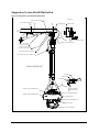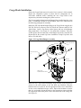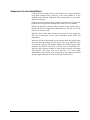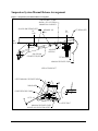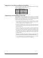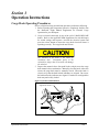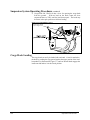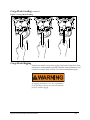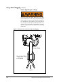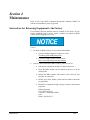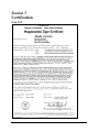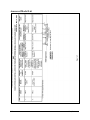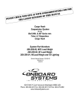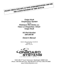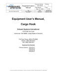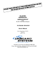
1
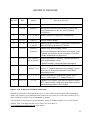
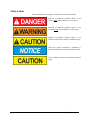
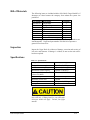
TALON MC KEEPERLESS CARGO HOOK KIT for the 204, 205, 212 & 412 Series Helicopters Part Number 200-246-00 Owner's Manual Owner's Manual Number 120-083-00 Revision 10 March 27, 2015 13915 NW 3rd Court Vancouver Washington 98685 USA Phone: 360-546-3072 Fax: 360-546-3073 Toll Free: 800-275-0883 www.OnboardSystems.com This page intentionally left blank. RECORD OF REVISIONS Revision Date Page(s) 2 6-19-00 Section 4 3 2-5-02 1-1, 2-3, and 41 4 9/17/02 Title, 4-3 5 8-7-03 1-1, 2-5, 3-1, 41, and 4-2 6 8-15-05 Section 3 Added Cargo Hook Loading section. Section 4 Removed maintenance information from section 4 and replaced with reference to service manual 122-004-00 (all the information was duplicated). 7 09/19/07 Reason for Revision Removed overhaul instructions from Section 4 and moved information to the new Service Manual 122-004-00 Added 528-020-02 Cargo Hook configuration. Factory address change. Added 528-020-04, and -06 Cargo Hook configuration. Moved RFMS to document 121-020-00 TOC, Section 1, Added explanation of warnings, cautions and notes to 2-4, & Section 3 general information section. Updated warnings, cautions and notes throughout. 8 05/15/12 1-3, 2-3, Section 3, 4-1 9 02/15/13 1-1, 2-3, 2-4, 31 10 03/27/15 1-1, 2-6 Added cargo hook P/N 528-020-10. Updated format of Section 3. Updated instructions for returning a system to the factory. Removed Functional Check Before Installation section. Removed reference to suspension system P/Ns for clarity. Added Figure 2-2. Updated Figure 3-1. Updated list of eligible cargo hook to replace to match STC, added caution stating cargo hook must be closed when adjusting manual release system. Register Your Products for Automatic Notifications Onboard Systems offers a free notification service via fax or email for product alerts and documentation updates. By registering your Onboard Systems products at our website, we will be able to contact you if a service bulletin is issued, or if the documentation is updated. You can choose to receive notices on an immediate, weekly, or monthly schedule via fax, email or both methods. There is no charge for this service. Please visit our website at www.onboardsystems.com/notify.php to get started. ii This page intentionally left blank. CONTENTS Section 1 General Information Introduction, 1-1 Safety Labels, 1-2 Bill of Materials, 1-3 Inspection, 1-3 Specifications, 1-3 Theory of Operation, 1-4 Section 2 Installation Instructions Suspension System Removal, 2-1 Cargo Hook Removal, 2-1 Suspension System Detail Illustration, 2-2 Functional Check Before Installation, 2-3 Cargo Hook Installation, 2-3 Suspension System Installation, 2-4 Suspension System Manual Release Arrangement, 2-5 Suspension System Manual Release Adjustment, 2-6 Suspension System Electrical Release Installation, 2-7 Suspension System Installation Check-Out, 2-7 Component Weights, 2-8 Paper Work, 2-8 Section 3 Operation Instructions Cargo Hook Operating Procedures, 3-1 Cargo Hook Loading, 3-2 Cargo Hook Rigging, 3-3 Section 4 Maintenance Instructions for Returning a System to the Factory, 4-1 Section 5 Certification FAA STC, 5-1 Approved Model List, 5-2 Canadian STC, 5-3 iii This page intentionally left blank. Section 1 General Information Introduction The 200-246-00 Cargo Hook Kit is approved as a replacement for the following cargo hooks on Cargo Hook Suspension Systems on Bell 204B, 205A, 205A-1, 212, 412, and 412EP models. Bell Cargo Hook Part Number 204-072-924-1 204-072-924-7 General Information Equivalent Breeze-Eastern Cargo Hook Part Number SP7109-1, -11 SP7109-62 SP7109-12 SP7109-93 1-1 Safety Labels The following definitions apply to safety labels used in this manual. Indicates a hazardous situation which, if not avoided, will result in death or serious injury. Indicates a hazardous situation which, if not avoided, could result in death or serious injury. Indicates a hazardous situation which, if not avoided, could result in minor or moderate injury. Draws the reader’s attention to important or unusual information not directly related to safety. Used to address practices not related to personal injury. 1-2 General Information Bill of Materials The following items are included with the 200-246-00 Cargo Hook Kit, if shortages are found contact the company from whom the system was purchased. Part Number Description Quantity 528-020-10* Cargo Hook 1 220-040-00 Bumper Ring 1 510-314-00 Cap Screw 2 290-210-01 Spacer 4 510-104-00 Nut 2 120-083-00 Owner's Manual 1 121-020-00 RFM Supplement 1 122-004-00 Service Manual 1 * Optional cargo hook part number is 528-020-06. These part numbers are interchangeable. Cargo hook part number 528-020-10 incorporates a ground crew release lever. Inspection Inspect the Cargo Hook for evidence of damage, corrosion and security of lock wire and fasteners. If damage is evident, do not use the unit until it has been repaired. Specifications Table 1-1 Specifications Design load Design ultimate strength Electrical release capacity Mechanical release capacity Force required for mechanical release at 6,000 lb. Electrical requirements Minimum release load Unit weight Mating electrical connector 6,000 lb. (2,721 kg.) 27,000 lb. (12,247 kg.) 15,000 lb. (6,804 kg.) 15,000 lb. (6,804 kg.) 18 lb. Max.(.400” travel) 22-28 VDC 9 amps 0 pounds 11.75 pounds (5.33 kg.) MS3106F16S-5S Load capacities given are for the equipment described only. Loading limits for your particular helicopter model still apply. Consult your flight manual. General Information 1-3 Theory of Operation The primary elements of the Cargo Hook are the load beam, the internal mechanism, and a DC solenoid. The load beam supports the load and is latched through the internal mechanism. The DC solenoid and an external manual release cable provide the means for unlatching the load beam. The load beam is normally held in the open position by a spring loaded detent. The load is attached to the load beam by passing the load ring into the throat of the load beam and pushing the ring against the upper portion of the load beam throat, which will initiate the hook to close. In the closed position, a latch engages the load beam and latches it in this position. To release the load, the latch is disengaged from the load beam. With the latch disengaged, the weight of the load causes the load beam to swing to its open position, and the load ring slides off the load beam. The load beam then remains in the open position awaiting the next load. A load release can be initiated by three different methods. Normal release is achieved by pilot actuation of the push-button switch in the cockpit. When the push-button switch is pressed, it energizes the DC solenoid in the Cargo Hook, and the solenoid opens the latch in the internal mechanism. In an emergency, release can be achieved by operating a mechanical release pedal. A manual release cable attached to the pedal operates the internal mechanism of the Cargo Hook to unlatch the load beam. The load can also be released by the manual actuation of the cable mechanism located above the Cargo Hook on the suspension. On –00, – 02, and -10 cargo hook configurations the load can also be released during ground operations by the actuation of a lever located on the side of the Cargo Hook. 1-4 General Information Section 2 Installation Instructions Suspension System Removal The Suspension System interfaces with several helicopter components, such as the cargo hook manual and electrical release provisions. Before removing the Cargo Hook Suspension System have available and be familiar with the Bell Service Instructions 204-3, 212-5 or later bulletins. See the Suspension System Detail Illustration located on the following page of this manual. Remove the cargo hook manual release cable at the 204-070-995 Connector. Loosen the 204-070-996-1 Clamp to allow the cable to slide through it. The Connector and the Clamp are located at approximately WL 39.87 and between BL 9.80 and BL 0.00, near the upper end of the suspension system. Disconnect the suspension system electrical connector located between the suspension system and airframe. Remove the Bell load bolt located at BL 0.00, WL 38.87 and Station 137.55, this will allow the suspension system to be removed through the bottom of the aircraft. Cargo Hook Removal To remove the Cargo Hook from the suspension system disconnect the lower manual release cable from the swing arm by removing the cotter pin located in the out-board end of the swing arm. Remove the cargo hook electrical connector located on the Cargo Hook between the two cargo hook retaining bolts. Remove the two cargo hook retaining bolts and separate the Cargo Hook from the suspension system. Remove the two bumper ring retaining bolts and separate the bumper ring from the Cargo Hook. Installation Instructions 2-1 Suspension System Detail Illustration Figure 2-1 Suspension System Detail Illustration DETAIL A 204-070-996-1 CLAMP 204-070-998 SPRING (REF) BL 9.80 BL 0.00 LIFT BEAM (REF) CABLE CLAMP WL 39.87 MANUAL RELEASE CABLE 204-070-995 CONNECTOR (REF) MANUAL RELEASE CABLE BELL 205-030-107 OR 204-030-841 HARD POINT BELL HELICOPTER LOAD BOLT ELECTRICAL RELEASE CONNECTOR VIEW LOOKING AFT STOP BOLT SWING ARM COTTER PIN CARGO HOOK RETAINING BOLT LOWER MANUAL RELEASE CABLE CARGO HOOK RETAINING BOLT BUMPER RING RETAINING BOLT BUMPER RING BUMPER RING RETAINING BOLT CARGO HOOK CARGO HOOK LOAD BEAM 2-2 Installation Instructions Cargo Hook Installation Ensure the Cargo Hook removed is on the list in section 1 of this manual. Inspect the suspension system to insure that all components are in serviceable condition before installing the new Cargo Hook to the suspension system and returning the system to service. The kit is normally shipped with the Bumper Ring installed onto the cargo hook. If installing a kit that is not assembled, refer to the instructions in the following paragraph for assembly. Install the P/N 220-040-00 Bumper Ring to the Cargo Hook using the two P/N 510-314-00 Cap Screws, four P/N 290-210-01 Spacers and P/N 510104-00 Nuts. Insert a Cap Screw with a Spacer into one of the Bumper Ring mount holes. See Figure 2-1 for mount hole locations. Place the second Spacer into the other side of the Bumper and secure with the Nut. Repeat this for the second Cap Screw installation. Torque Cap Screw and Nuts to 120-160 in-lbs. Figure 2-2 Cargo Hook/Bumper Assembly Spacer P/N 290-210-01 Qty 4 Nut P/N 510-104-00 Qty 2 Bolt P/N 510-314-00 Qty 2 Bumper P/N 220-040-00 Cargo Hook P/N 528-020-10 shown Install the new Cargo Hook and Bumper Ring assembly to the suspension system, in the same manner as the old hook was installed, using the hardware that was removed. See the appropriate Bell service instructions for the correct installation torque values. Inspect the hardware to insure that it is serviceable. Orient the hook to the suspension system such that the cargo hook load beam points in the same direction as the swing arm. See Figure 2-1. Installation Instructions 2-3 Suspension System Installation Connect the lower manual release cable between the swing arm and the cargo hook manual release provisions, in the same manner as it was installed on the old hook. Inspect the cable to insure that it is serviceable. Install the cotter pins. Connect the cargo hook electrical connector located on the Cargo Hook between the two cargo hook retaining bolts. Safety wire the connector. Position the Suspension System with the manual release control cable on the left and the clevis aligned in the Bell hard point, 205-030-107 or 204030-841, at waterline 38.87. Install the bolt, washer and nut removed previously. See the appropriate Bell service instructions for the correct installation, torque values and maintenance. Route the free end of the manual release cable aft and to the right (looking aft) of the hard point fitting. See the Suspension System Manual Release Arrangement section of this manual. Engage ball terminal into the cable connector 204-070-995 and secure with the cotter pin MS24665-155. Place the outer housing (conduit) of control cable assembly into clamp 204-070-996-1 and secure with screw AN520-1 or 12 and washer AN960PD10L into nut plate in existing structure. The conduit end should measure approximately 0.42 inches from clamp 204-070-996-1. 2-4 Installation Instructions Suspension System Manual Release Arrangement Figure 2-3 Suspension System Manual Release Arrangement 204-070-996-1 CLAMP AN520 1 OR 12 SCREW AN960PD10L WASHER 204-070-998 SPRING (REF) BL 9.80 MS24665-155 PIN BL 0.0 LIFT BEAM (REF) WL 39.87 204-070-995 CONNECTOR (REF) .42 INCH APPROX FITTING (REF) MANUAL RELEASE CABLE VIEW LOOKING AFT UPPER MANUAL RELEASE CABLE SWING ARM .03 .08 LOWER RELEASE CABLE .10" .12 TO .18 STOP BOLT MANUAL RELEASE LEVER -00 AND -02 HOOKS ONLY(REF) Installation Instructions 2-5 Suspension System Manual Release Cable Adjustment Manual release cable adjustment must be done with the cargo hook in the closed and locked position. Adjust the conduit of the manual release cable to obtain 0.03 to 0.08 inch dimension shown in the previous section and secure clamp shown in detail A of the Suspension System Detail section. Adjust connector 204-070-995, shown in the previous section to obtain 0.10 inch over-travel in the control cable as shown in the previous section. The stop bolt of the swing arm should be in contact with the top of the cargo hook case and the swing arm should be parallel to the plane of the main hook attachment bolts when the 0.10 inch measurement is taken. By grasping the top of the lower control cable, apply tension until all the backlash is taken out. Measure the clearance of the lower control cable ball terminal to the swing arm as shown in Figure 2-2. This measurement shall be 0.12 to 0.18 inches when system is rigged and load beam is latched. If adjustment is made to the stop bolt in order to obtain proper clearance, recheck adjustment of control cable and conduit. With the cargo hook release pedal against the FORWARD stop, check for the following conditions: 2-6 Ensure that the spring assembly 204-070-998, does not bottom. If the spring assembly should bottom, return the cargo hook pedal to the aft stop and check control cable tension. Cable tension should be 20 to 24 pounds. Check the operation of the mechanical release with at least 20 pounds load on the cargo hook load beam. Ensure the swing arm is full up. Ensure lever is not stopped by the bottom end of the control cable outer housing. Ensure cargo hook load beam unlocks. Release the cargo hook pedal and ensure that both the upper and lower manual release cables return to the locking position. See the Bell Helicopter service instructions that cover the original cargo hook suspension system for additional instructions. Installation Instructions Suspension System Electrical Release Installation Connect the electrical release cable to the connector located on the right underside of the lift beam and safety wire. Table 2-1 Cargo Hook Connector PIN FUNCTION B Power C Ground Suspension System Installation Check-Out After installation of the Suspension System, perform the following functional checks. Follow the Bell Helicopter instructions for the specific helicopter. Direct an assistant to observe the Cargo Hook and reset the cargo hook load beam to the closed position as required. 1. Ensure that the manual release cable assembly and the electrical release cable have enough slack to allow full swing of the suspension assembly without straining or damaging the cables. 2. Close the cargo hook release circuit breaker and position the battery switch to the ON position. Depress the cargo hook switch. The Cargo Hook should release. 3. Rotate the suspension system 90 degrees, close the cargo hook and repeat step 3. Rotate the suspension system another 90 degrees, close the cargo hook and repeat step 3. Repeat this procedure until the suspension system is back at its original position. To prevent burning out the solenoid do not hold the switch for more than 5 seconds in any 30 second period. 4. With the cargo hook closed, depress the foot operated cargo hook mechanical release in the cockpit, the Cargo Hook should release. 5. See the Bell Helicopter service instructions that cover the original cargo hook suspension system for additional instructions. Installation Instructions 2-7 Component Weights The weight of the 200-246-00 Cargo Hook kit is 17.5 pounds. This is approximately the same weight as the Cargo Hook and Bumper it replaced. Paper Work Place the Rotorcraft Flight Manual Supplement, 121-020-00, into the Rotorcraft Flight Manual. In the US, fill in FAA form 337 for the initial installation. This procedure may vary in different countries. Make the appropriate aircraft log book entry. 2-8 Installation Instructions Section 3 Operation Instructions Cargo Hook Operating Procedures Prior to a flight involving external load operations perform the following. 1. Before operating the Suspension System be completely familiar with the Rotorcraft Flight Manual Supplement for External Cargo Operation for your helicopter. 2. Cargo is released electrically by use of the cyclic CARGO RELEASE button. Refer to the applicable RFM Supplement for each helicopter for switch settings and sequence. Activate the electrical system and press the release button to ensure the cargo hook electrical release is operating correctly. The cargo hook must release. The solenoid in the hook is not rated for continuous duty. Continuous power to the solenoid for longer than 30 seconds will damage the solenoid. 3. Depress the manual release foot pedal in the cockpit to test the cargo hook manual release mechanism. Manually close the hook. After each release the cargo hook must be manually closed. When the hook is closed, verify that the hook locked indicators are aligned. Do not use the hook unless the indicators are aligned. If marks are not aligned the hook may not be fully locked. Figure 3-1 Hook Locked Indication Engraved lines must be aligned as shown Operation Instructions 3-1 Suspension System Operating Procedures continued 4. Cargo hook P/N 528-020-10 has a lever for opening the cargo hook from the ground. With no load on the hook, rotate the lever counterclockwise (CCW) until the load beam opens. The hook may be flown in the open position to facilitate loading. Figure 3-2 Ground Release Lever Rotate lever CCW to open cargo hook. Cargo Hook Loading The cargo hook can easily be loaded with one hand. A load is attached to the hook by pushing the ring upward against the upper portion of the load beam throat, as illustrated in Figure 3-3, until an internal latch engages the load beam and latches it in the closed position. 3-2 Operation Instructions Cargo Hook Loading continued Figure 3-3 Cargo Hook Loading LOCKED LOCKED LOCKED 6,000 LB Rated Capacity 6,000 LB Rated Capacity 6,000 LB Rated Capacity Part # 528-020- Part # Date S/N 528-020- Date S/N SEE STC LIST FOR APPROVED AIRCRAFT www.onboardsystems.com Form 215-159-00 FAA - PMA SEE STC LIST FOR APPROVED AIRCRAFT www.onboardsystems.com Form 215-159-00 FAA - PMA Part # 528-020- Date S/N SEE STC LIST FOR APPROVED AIRCRAFT www.onboardsystems.com Form 215-159-00 FAA - PMA Cargo Hook Rigging Extreme care must be exercised in rigging a load to the Cargo Hook. Steel load rings are recommended to provide consistent release performance and resistance to fouling. Refer to Figure 3-4 for the recommended rigging. The example shown is not intended to represent all rigging possibilities. It is the responsibility of the operator to assure the hook will function properly with the rigging. Suspension System Operation Instructions 3-3 Cargo Hook Rigging continued Nylon Type Straps or Rope Nylon type straps (or similar material) or rope must not be used directly on the cargo hook load beam. If nylon straps or rope must be used they should be first attached to a steel primary ring. Verify that the ring will freely slide off the load beam when it is opened. Only the primary ring should be in contact with the cargo hook load beam. See following illustration. Figure 3-4 Example of Recommended Cargo Hook Rigging Primary Ring Secondary Ring or Shackle Load 3-4 Suspension System Operation Instructions Section 4 Maintenance Refer to the Cargo Hook Component Maintenance Manual (CMM) 122004-00 for maintenance of the cargo hook. Instructions for Returning Equipment to the Factory If an Onboard Systems product must be returned to the factory for any reason (including returns, service, repairs, overhaul, etc) obtain an RMA number before shipping your return. An RMA number is required for all equipment returns. To obtain an RMA, please use one of the listed methods. Contact Technical Support by phone or e-mail ([email protected]). Generate an RMA number at our website: http://www.onboardsystems.com/rma.php After you have obtained the RMA number, please be sure to: Package the component carefully to ensure safe transit. Write the RMA number on the outside of the box or on the mailing label. Include the RMA number and reason for the return on your purchase or work order. Include your name, address, phone and fax number and email (as applicable). Return the components freight, cartage, insurance and customs prepaid to: Onboard Systems 13915 NW 3rd Court Vancouver, Washington 98685 USA Phone: 360-546-3072 Maintenance 4-1 This page intentionally left blank. Section 5 Certification FAA STC Certification 5-1 Approved Model List 5-2 Certification Canadian STC Certification 5-3 5-4 Certification