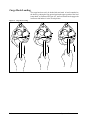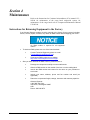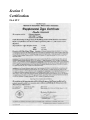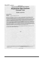
1
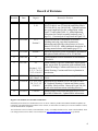
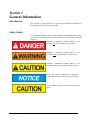
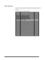
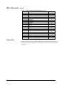
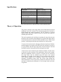
Cargo Hook Suspension System For the Robinson R44 Series With Talon LC Keeperless 12Volt Cargo Hook Kit Part Number 200-265-00 Owner's Manual Owner's Manual Number 120-097-00 Revision 12 March 18, 2011 13915 NW 3rd Court Vancouver, Washington 98685 USA Phone: 360-546-3072 Fax: 360-546-3073 Toll Free: 800-275-0883 www.OnboardSystems.com This page intentionally left blank. Record of Revisions Revision Date Page(s) Reason for Revision 5 10/20/05 1-1, 1-2, 2-1, 22, 4-1 6 02/15/06 2-13, Section 5 Incorporated new configurations for Gimbal Assembly (P/N 232-049-01 was 232-049-00) and Pillow Block (P/N 290-492-01 was 290-492-00). Updated hardware (new grip length bolt) for this configuration within Figure 2-1 and within Table 1-1. Added tightening instructions for Gimbal Assembly hardware (step 7, page 2-1). Corrected p/n of cargo hook in Figure 2-2. Updated maintenance information in Section 5 including removing cargo hook maintenance information and replacing with reference to Service Manual 122-012-00. Added additional description for locating manual release cable handle (page 2-13). 7 03/15/06 Section 5 8 09/07/06 1-1 9 05/31/07 4-1 Added warning of specific maintenance requirements when system used for operations with rotational loads. Section 1, 2-13, Updated Warnings, Cautions and Notes to new format. 2-17, 3-7 to 3-9, Added Warning, Cautions and Notes explanation in 3-12, 4-1 & 4-2 introduction. 10 02/26/08 TOC, 1-2, 1-3 & 2-9 thru 2-18 Updates to allow use of switch assembly P/N 232114-01. 11 11/09/10 1-1, 2-12, 2-16, 3-8, 3-9, 3-12, 4-1 & 4-2 Replaced service manual 122-012-00 with 122-00500. Replaced Warnings, Cautions and Notes section with Safety Labels section. Removed kit p/n 200-26600 and associated instructions including Section 3. 12 03/18/11 1-2 & 4-1 Removed suspension system maintenance information and replaced with reference to ICA 123-005-00. Updated manual to allow installation of wire harness 270-048-04. Added External Load Limit 800 Decal P/N 215-11900 to Bill Of Materials. Updated RMA information. Register Your Products for Automatic Notifications Onboard Systems offers a free notification service via fax or email for product alerts and documentation updates. By registering your Onboard Systems products at our website, we will be able to contact you if a service bulletin is issued, or if the documentation is updated. You can choose to receive notices on an immediate, weekly, or monthly schedule via fax, email or both methods. There is no charge for this service. Please visit our website at www.onboardsystems.com/notify.php to get started. ii This page intentionally left blank. CONTENTS Section 1 General Information Introduction, 1-1 Warnings, Cautions and Notes, 1-2 Bill of Materials, 1-2 Inspection, 1-3 Specifications, 1-4 Theory of Operation, 1-4 Section 2 Installation Instructions Pillow Block, Gimbal and Link Installation, 2-1 Electrical Schematic, 2-3 Wire Harness and Relay, 2-4 Wiring to Circuit Breaker Panel and Circuit Breaker Installation, 2-6 Release Switches Installation, 2-6 Mechanical Release Cable Installation, 2-12 Electrical Release Wire Routing to the Hook, 2-14 Attaching the Mechanical Release Cable to Cargo Hook, 2-15 Cargo Hook Installation, 2-16 Wiring Connector, 2-16 Decals and Placards, 2-17 Installation Check-Out, 2-18 Component Weights, 2-18 Cargo Hook Location, 2-18 Paper Work, 2-18 iii CONTENTS, continued Section 3 Operation Instructions Operating Procedures, 3-1 Optional Flight Configuration, 3-1 Cargo Hook Rigging, 3-2 Cargo Hook Loading 3-4 Section 4 Maintenance Instructions for Returning a System to the Factory, 4-1 Section 5 Certification FAA STC, 5-1 Canadian Approval, 5-3 EASA STC, 5-4 Figures 2-1 2-2 2-3 2-4 2-5 2-6 2-7 2-8 2-9 2-10 2-11 2-12 2-13 2-14 3-1 3-2 Gimbal, Load Cell and Hook Hardware, 2-2 Electrical Schematic, 2-3 Wire Harness and Relay Installation, 2-4 Relay Installation, 2-5 Cyclic Switch Wire Routing, 2-7 Cyclic Release Switch Installation, 2-8 Grip Assembly C058, Plug Removal, 2-9 Grip Assembly C058, Screw and Nut Removal, 2-9 Grip Assembly, 2-10 Left Seat Release Switch Installation, 2-11 Manual Release Cable Installation, 2-12 Manual Release Cable Routing, 2-14 Manual Release Cable Rig, 2-15 Cargo Hook Installation, 2-16 Examples of Recommended Cargo Hook Rigging, 3-3 Cargo Hook Loading, 3-4 Tables 1-1 1-2 2-1 2-2 2-3 2-4 iv Bill of Materials, 1-1 Cargo Hook Specifications, 1-3 Cargo Hook Connector, 2-16 Decals, 2-17 Component Weight, 2-18 Cargo Hook Location, 2-18 Section 1 General Information Introduction The 200-265-00 Cargo Hook Kit is approved for the Robinson R44 Series Helicopters with 12 volt electrical systems. Safety Labels The following definitions apply to the symbols used throughout this manual to draw the reader’s attention to safety instructions as well as other important messages. Indicates a hazardous situation which, if not avoided, will result in death or serious injury. Indicates a hazardous situation which, if not avoided, could result in death or serious injury. Indicates a hazardous situation which, if not avoided, could result in minor or moderate injury. Draws the reader’s attention to important or unusual information not directly related to safety. Used to address practices not related to personal injury. General Information 1-1 Bill of Materials The following items are included with the Cargo Hook Suspension System. If shortages are found contact the company from whom the system was purchased. Table 1-1 Suspension System Bill of Materials Part No. 120-097-00 121-007-00 122-005-00 123-005-00 215-118-00 215-119-00 232-049-01 232-050-00 232-063-00 232-114-01 268-014-01 270-089-00 270-090-00 290-440-00 290-478-01 290-492-01 290-505-00 400-053-00 400-054-00 400-059-00 410-162-00 440-006-00 1-2 Description System Owner’s Manual RFM Supplement Cargo Hook Service Manual ICA Maintenance Manual R22/44 Multiple Decal Sheet External Load Limit 800 Decal Gimbal Assembly Link Assembly Cyclic Switch Housing Assembly Switch Housing Assembly Release Cable Assembly Wire Assembly – Circuit Breaker Wire Bundle Roller Pin Switch Guard Pillow Block Drilled Cap Head Screw Switch Cap Switch Ring Terminal Circuit Breaker Qty 1 1 1 1 1 1 1 1 1 1 1 1 1 1 1 1 2 1 1 1 2 1 General Information Bill of Materials, continued Table 1-1 Suspension System Bill of Materials continued Part No. 445-002-00 500-065-00 500-066-00 505-011-00 510-100-00 510-115-00 510-209-00 510-273-00 510-277-00 510-278-00 510-279-00 510-286-00 510-297-00 510-301-00 510-528-00 512-010-00 512-018-00 528-023-03 Description Relay Grommet Spacer Grommet Washer Cotter Pin Washer Nut Screw Washer Nut Nut Screw Screw Bolt Clamp Adel Clamp 3,500 Lb. Cargo Hook Qty 1 1 1 1 1 1 1 1 2 2 2 1 1 2 1 2 2 1 Inspection Inspect the kit items for evidence of damage, corrosion and security of lock wire and fasteners. If damage is evident, do not use the items until they are repaired. General Information 1-3 Specifications Table 1-2 P/N 528-023-03 Cargo Hook Specifications Design load Design ultimate strength Electrical release capacity Mechanical release capacity Force required for mechanical release at 3,500 lb. Electrical requirements Minimum release load Unit weight Mating electrical connector 3,500 lb. (1,580 kg.) 15,750 lb. (7,140 kg.) 8,750 lb. (3,970 kg.) 8,750 lb. (3,970 kg.) 8 lb. Max.(.600” travel) 10-15 VDC 7.7-11.5 amps 0 pounds 3.0 pounds (1.35 kg.) PC06A8-2S SR These specifications are for the hook only, not the installed system. Theory of Operation The primary elements of the Cargo Hook are the load beam, the internal mechanism, and a DC solenoid. The load beam supports the load and is latched through the internal mechanism. The DC solenoid, an external manual release cable and a manual release lever provide the means for unlatching the load beam. The load is attached to the load beam by passing the cargo sling ring into the throat of the load beam and pushing the ring against the upper portion of the load beam throat, which will initiate the hook to close. In the closed position, a latch engages the load beam and latches it in this position. To release the load, the latch is disengaged from the load beam. With the latch disengaged, the weight of the load causes the load beam to swing to its open position, and the cargo sling slides off the load beam. The load beam then remains in the open position awaiting the next load. A load release can be initiated by three different methods. Normal release is achieved by pilot actuation of the push-button switch in the cockpit. When the push-button switch is pressed, it energizes the DC solenoid in the Cargo Hook, and the solenoid opens the latch in the internal mechanism. A secondary release button is also provided on the left seat lower outboard support. In an emergency, release can be achieved by operating a mechanical release cable. The release cable operates the internal mechanism of the Cargo Hook to unlatch the load beam. The load can also be released by the actuation of a lever located on the side of the Cargo Hook 1-4 General Information Section 2 Installation Instructions These procedures are provided for the benefit of experienced aircraft maintenance facilities capable of carrying out the procedures. They must not be attempted by those lacking the necessary expertise. The R44 maintenance and parts manuals should be available throughout the installation as various R44 components will be referred to by name and part number. The part numbers for Robinson components are provided for reference and may be changed at a later time by Robinson. All equipment removed and replaced shall be done in accordance with the R44 maintenance manual. All installed hardware shall be torque in accordance with standard torque’s of AC43.13 unless noted otherwise. Apply torque stripe where applicable. 1. Disconnect the battery. Pillow Block, Gimbal and Link Installation 1. Insert the 290-505-00 cap screws into the two holes in the Robinson hard point block and screw in to ensure thread integrity. Some rework of access holes in skin may be required to allow bolt installation. 2. Remove the two cap screws. 3. Place the Pillow Block, P/N 290-492-01, against the lower skin and install one of the cap screws as shown in Figure 2-1. 4. Partially insert the Roller Pin, P/N 290-440-00, into the Pillow Block, P/N 290-492-01. Hold the Gimbal Assembly, P/N 232-049-01, in position and slide the Roller Pin through the Gimbal Assembly and into the other side of the Pillow Block. Grease the roller pin with Aeroshell 7, MIL-G-23827 or equivalent before assembly. 5. Install the second cap screw and torque both screws to 26 ft-lbs. 6. Safety wire the cap screws to the safety wire ears on the Pillow Block. 7. Grease the bushings with Aeroshell 7, MIL-G-23827, or equivalent before assembly. Install the Load Cell Assembly, P/N 210-181-00, or the Link Assembly, P/N 232-050-00, to the Gimbal Assembly using the hardware shown in Figure 2-1. Install the load cell or link so that the travel limiter identified with the F is facing forward and the travel limiter identified with the A is facing aft. Tighten nut finger tight and then tighten to next available slot for cotter pin. Install new cotter pin. Installation Instructions 2-1 Pillow Block, Gimbal and Link Installation, continued Figure 2-1 Gimbal, Load Cell and Hook Hardware 290-440-00 ROLLER PIN 290-505-00 CAP SCREW (2 PLCS) 232-049-01 GIMBAL ASSEMBLY 210-181-00 LOAD CELL ASSY OR 232-050-00 LINK ASSY 510-100-00 WASHER (AN960-416L) 290-492-01 PILLOW BLOCK 510-273-00 NUT (BACN10JD104) 510-528-00 BOLT (NAS6204-12D) 510-115-00 COTTER PIN (MS24665-136) LOOKING FORWARD 2-2 Installation Instructions Electrical Schematic The electrical release system is powered from the bus through a 10 amp circuit breaker to a relay in the center tunnel. Switches on the cyclic and copilots seat support control the relay and energize the DC solenoid in the Cargo Hook, opening the hook and releasing the cargo. A schematic for the electrical system is shown below in Figure 2-2. Figure 2-2 Electrical Schematic OPTIONAL LEFT SEAT SWITCHNO 400-059-00 2B C 4A 2A 4B CYCLIC SWITCH 400-059-00 C NO 22G 22G 5 AIRFRAME GROUND 410-131-00 (PC06A8-25(SR)) 4 BUS 440-006-00 16G 10 AMP 16G 16G 16G 16G 270-090-00 WIRE BUNDLE 1 2 3 16G 6 SPADE CONNECTORS (REF) A 528-023-03 CARGO HOOK (PC07A-8-2P) B 7 5 445-002-00 RELAY Installation Instructions 2-3 Wire Harness and Relay Install the P/N 445-002-00 relay on the keel panel below the existing relay installation using the correct hardware as shown in Figure 2-3 and 2-4. Place the P/N 270-090-00 main wire bundle into the tunnel on top of the existing wire bundle. Figure 2-3 Wire Harness and Relay Installation 440-006-00 CIRCUIT BREAKER USE EXISTING AVAILABLE LOCATION 215-112-00 DECAL WIRES 2B & 4B TO LEFT SEAT SWITCH 505-011-00 GROMMET 270-090-00 WIRE BUNDLE EXISTING RELAY 445-002-00 RELAY SEE FIGURE 2-4 2-4 Installation Instructions Wire Harness and Relay, continued Connect wire numbers 1, 2 and 3 from the main bundle to the relay terminals A, B and 7 as shown in the Figure 2-2 electrical system schematic. Connect jumper wire 6 to relay terminal 5. Connect the ground lead of wire number 5 to any convenient existing ground location in the tunnel. Secure the wire bundle with wire ties as required. Figure 2-4 Relay Installation EXISTING RELAY 4.75 510-277-00 (MS35206-228) (SCREW) 510-279-00 (NAS679A06) (NUT) 2.52 +.04 -.00 A A 445-002-00 RELAY Installation Instructions 510-278-00 (AN960L) (WASHER) .157 DIA HOLE (2 PLCS) SECTION A-A (2 PLCS) 2-5 Wiring to Circuit Breaker Panel and Circuit Breaker Installation 1. Remove the circuit breaker cover panel and install the P/N 440-006-00 10 amp circuit breaker in an available location. On some early models, it may be necessary to remove the panel and make a hole for the additional circuit breaker. 2. Open the circuit breaker to disarm the cargo hook release circuit. 3. Use the P/N 270-089-00 wire assembly and a P/N 410-162-00 ring terminal as a jumper to power the input side of the circuit breaker in compliance with AC 43.13. 4. Feed the number 1 wire of the main wire bundle from the tunnel into the circuit breaker bay using the existing wire bundle access hole. Connect the wire to the output side of the P/N 440-006-00 circuit breaker using the other P/N 410-162-00 ring terminal provided. Secure the power wire to the existing wire bundles with tie wraps. Release Switches Installation Cyclic Release Switch Installation 1. Remove the cover to the cyclic switch housing and ensure its wires are clear of the areas to be drilled on the horizontal cyclic control handle. 2. Drill a .172 inch diameter hole on the forward side of the cyclic grip as shown in Figure 2-5. 3. Use a lead wire and route the number 2A and 4A wires up through the cyclic stick and out the existing wire routing hole. Place a length of heat shrink over the wires that will cover the exposed portion similar to the existing com wires. 4. Using a lead wire again, pull the number 2A and 4A wires up through the cyclic grip and out the .172 hole on the front of the cyclic grip. 5. Place a 1 inch length of heat shrink over each wire to the cyclic switch. Prepare each wire end and solder them to the normally open and closed switch terminals as shown in the Figure 2-2 wiring schematic. Using a heat gun, shrink the covering material to final size. 2-6 Installation Instructions Release Switches Installation, continued Figure 2-5 Cyclic Switch Wire Routing .50 CYCLIC GRIP (REF) EXISTING HOLES Ø.172 (DRILLED IN STEP #2) CYCLIC STICK (REF) LOOKING AFT Installation Instructions 6. Install the 400-053-00 switch in the 232-063-00 cyclic switch housing assembly using needle nose pliers to hold the switch. Install the completed switch housing assembly with the correct hardware as shown in Figure 2-6. Remove the existing switch housing screws and replace them with the longer 510-301-00 screws and salvage one of the removed nuts as shown in Figure 2-6. 7. Re-install the com switch housing and wires. 8. Check the cyclic for freedom of motion throughout its complete travel range and ensure the wires are not chafing on any components. 2-7 Release Switches Installation, continued Figure 2-6 Cyclic Release Switch Installation 232-063-00 SWITCH HOUSING ASSY 400-054-00 CAP 400-053-00 SWITCH SALVAGE NUT CARGO RELEASE 215-110-00 DECAL 510-301-00 SCREW (2 PLCS) 2-8 Installation Instructions Release Switches Installation, continued Grip Assembly Switch Installation (for use with Robinson Grip Assembly C058) 1. Remove Plug (Robinson P/N DP-875) and discard as shown in Figure 2-7. Figure 2-7 Grip Assembly C058, Plug Removal Remove plug and discard. 2. Remove outboard screw (MS27039C0806) and nut (MS21042L08) as shown in Figure 2-8. Figure 2-8 Grip Assembly C058, Screw and Nut Removal Remove outboard screw and nut. Installation Instructions 2-9 Release Switches Installation, continued Grip Assembly Switch Installation, continued 3. Using a lead wire, pull the number 2A and 4A wires from wire harness P/N 270-090-00 up through the horizontal tube and out the end of the grip assembly. 4. Slide a piece of heat shrink (P/N 450-001-00) over the 2A and 4A wires (ref. Figure 2-9). 5. Prep and solder, using a lap splice, the 2A wire from up through the cyclic to one of the wires from the switch and the 4A wire from the cyclic to the other wire from the switch. 6. Slide the heat shrink over the respective solder joints and shrink in place using a heat gun. Figure 2-9 Grip Assembly C058 Cyclic Switch Housing Assembly R44 Cyclic Grip P/N 232-114-01 A Heat Shrink, 1/2" Lg. P/N 450-001-00 A Install Placard P/N 215-110-00 here. VIEW A-A 7. Install the Switch Housing Assembly into the end of the grip assembly and secure with the Screw (P/N MS27039C0806) removed earlier. The Nut (P/N MS21042L08) removed earlier will not be re-used for this installation and can be discarded. 8. Check the cyclic for freedom of motion throughout its complete travel range and ensure the wires are not chafing on any components. 2-10 Installation Instructions Release Switches Installation, continued Optional Left Seat Release Switch Installation If the left seat release switch installation is not desired, cap and stow wires 2B and 4B per AC 43.13 and skip this section. 1. Drill a .250 inch hole in the left side of the tunnel wall above the main wire bundle in a convenient location or use an existing unused hole in the tunnel wall. Install Grommet (P/N 505-011-00). 2. Drill a .50 inch hole in the outboard side of the left seat support as shown in Figure 2-10. 3. Route the number 2B and 4B wires through the grommeted hole and through the left baggage area to the .50 inch hole on the outboard seat support. Secure the wires to the forward seat hinge fasteners with two clamps (P/N 512-018-00). 4. Slide the nut (provided with the switch P/N 400-059-00) over the wires from inside the seat support and feed the wires through the .50 inch hole and through the switch guard (P/N 290-478-01). 5. Place a .50 inch length of heat shrink over each wire to the switch. Solder the wires to the switch as shown in the Figure 2-2 wiring schematic. Use a heat gun and shrink the covering material to final size. Place the switch (P/N 400-059-00) into the switch guard and through the seat as shown in Figure 2.10 and secure with nut. Figure 2-10 Left Seat Release Switch Installation Switch Guard P/N 290-478-01 LEFT SEAT 1.00 in. (25.4 mm) A Drill .50 in. (12.7 mm) hole in seat support. Switch P/N 400-059-00 SECTION A - A Installation Instructions 1.60 in. 41 mm A CARGO RELEASE Placard P/N 215-110-00 2-11 Mechanical Release Cable Installation Install the mechanical release cable T-handle on the cyclic control cover in the location shown in Figure 2-11. If, due to configuration changes by Robinson Heliopters, this location is not available, locate it as near as possible, or locate on opposite side (in lower right corner) of cyclic control cover. Important: Before proceeding with drilling hole for T-handle, verify there is clearance beneath the cyclic control cover for the release cable to extend down. 1. Drill a .38 inch diameter hole through the left aft corner of the cyclic control cover and box assembly as shown in Figure 2-11. Locate and drill the hole for the cable clamp in the tunnel keel panel as shown in Figure 2-11. 2. Place the 268-014-01 mechanical release cable inside the tunnel and route the output end of the cable out the bottom of the helicopter. Insert the forward end of the cable into the cyclic control cover plate and install the face nut and T-handle as shown in Figure 2-11. Install the cable clamp as shown in Figure 2-11 (install on same side as Thandle) and secure the release cable to it. Verify that the mechanical release cable does not interfere with push/pull control rods and electrical components in the tunnel and that there is sufficient clearance between these items to allow for motion and account for any slack. 3. Make a cutout in the forward belly panel as shown in Figure 2-12 and install the 500-065-00 edge grommet. 4. Route the mechanical release cable as shown in Figure 2-12 and secure. 2-12 Installation Instructions Mechanical Release Cable Installation, continued Figure 2-11 Manual Release Cable Installation ELT SWITCH Ø.38 A CARGO RELEASE .63 PULL .45 215-110-00 DECAL A 215-112-00 DECAL ADEL CLAMP P/N 512-010-00 WASHER P/N 510-209-00 SCREW P/N 510-297-00 NUT P/N 510-286-00 CYCLIC CONTROL COVER SPACER P/N 500-066-00 TUNNEL KEEL PANEL (REF) FWD 268-014-01 MANUAL RELEASE CABLE ASSEMBLY SECTION B-B B BOTTOM SKIN B 1.75 2.38 MEASURE FROM FORWARD PANEL OPENING. SECTION A-A Installation Instructions 2-13 Electrical Release Wire Routing to the Hook Route the #3 and #4 electrical release wires out the same hole in the forward panel as the mechanical release cable as shown in Figure 2-12. Secure the two release wires to the mechanical release cable with wire ties as necessary and route as shown in Figure 2-12. Figure 2-12 Manual Release Cable Routing LOOKING UP FWD FORWARD PANEL LEFT OUTBOARD 500-065-00 GROMMET AFT PANEL 268-014-01 MANUAL RELEASE CABLE AND ELECTRICAL RELEASE WIRE BUNDLE 512-010-00 CLAMP USE EXISTING SCREW 2-14 Installation Instructions Attaching the Mechanical Release Cable to Cargo Hook 1. Remove the manual release cover from the 528-023-03 Cargo Hook. 2. Screw the manual release cable into the hook by holding the cable and turning the hook assembly. 3. Place the cable ball end fitting into the hook manual release fork fitting as illustrated in Figure 2-13. Move the manual release lever in the clockwise direction until it is against the cam stop. Measure the cable ball end free play with the manual release handle in the cockpit in the non-release position. Adjust the manual release cable system to allow .125” of free play at the fork fitting as shown in Figure 2-13. 4. Replace the manual release cover. Tighten the jam nut against the hook and safety wire the jam nut to the nearest cover screw. Safety wire the remaining cover screws. Figure 2-13 Manual Release Cable Rig MANUAL RELEASE CABLE MANUAL RELEASE LEVER FORK FITTING Installation Instructions .125 BALL END FITTING 2-15 Cargo Hook Installation Install the P/N 528-023-03 Cargo Hook assembly to the link using the correct hardware as shown in Figure 2-14. The cargo hook load beam should point forward. Figure 2-14 Cargo Hook Installation AN WASHER P/N 510-183-00 (AN 960-816L) NAS WASHER P/N 510-174-00 (NAS 1149F0663P) 232-050-00 LINK ASSY OR 210-181-00 LOAD CELL LINK MS COTTER PIN P/N 510-178-00 (MS24665-302) LOAD BOLT P/N 290-332-00 AN NUT P/N 510-170-00 (AN 320-C6) CARGO HOOK AN WASHER P/N 510-183-00 (AN 960-816L) MANUAL RELEASE SIDE OF HOOK Tighten nut P/N 510-170-00 on bolt P/N 290-332-00 to finger tight, then rotate to next castellation to install and secure cotter pin P/N 510-178-00 Wiring Connector Connect the cargo hook electrical release cable connector to the Cargo Hook. Listed below is the pin out for the cargo hook connector. Safety wire the connector. Table 2-1 Cargo Hook Connector Pin Function A Ground B Power The Cargo Hook is equipped with a suppression diode that will be damaged if the Cargo Hook electrical connections are reversed. Do not attach the electrical connector until the polarity of the aircraft connector is determined to be compatible with the Cargo Hook connector listed in Table 21. 2-16 Installation Instructions Decals and Placards Install the following decals: Table 2-2 Decals DECAL NUMBER LOCATION (DECAL DESCRIPTION) P/N 215-110-00 Mounted adjacent to the cyclic release switch in clear view of the pilot. (CARGO RELEASE) P/N 215-110-00 (CARGO RELEASE) P/N 215-110-00 (CARGO RELEASE) P/N 215-111-00 (PULL) P/N 215-112-00 Mounted adjacent to the left seat release switch in clear view of the pilot. (See Figure 2-10) Mounted adjacent to the mechanical release in clear view of the pilot. (See Figure 2-11) Mounted adjacent to the mechanical release in clear view of the pilot. (See Figure 2-11) Mounted adjacent to the cargo hook circuit breaker in clear view of the pilot (CARGO) P/N 215-114-00 Mounted on the instrument panel in clear view of the pilot. (CLASS B ROTORCRAFT..) P/N 215-115-00 Mounted on the instrument panel in clear view of the pilot. (FAR PART 133.35(A) OPERATIONS ...) P/N 215-119-00 (EXTERNAL LOAD LIMIT = 800 LBS (363 KGS)) Installation Instructions Mounted on the belly of the aircraft adjacent to the cargo hook attachment point in clear view of the ground support personnel. 2-17 Installation Check-Out After installation of the Cargo Hook Suspension System, perform the following functional checks. 1. Swing the installed Cargo Hook to ensure that the manual release cable assembly and the electrical release cable have enough slack to allow full swing of the suspension assembly without straining or damaging the cables. The cables must not be the stops that prevent the Cargo Hook from swinging freely in all directions. 2. With no load on the cargo hook load beam, pull the handle operated cargo hook mechanical release, the Cargo Hook should release. Reset the cargo hook load beam. 3. Close the cargo hook release circuit breaker and position the battery switch to the ON position. With no load on the cargo hook load beam, depress the cargo hook electrical release button, the Cargo Hook should release. using the cyclic and left seat electrical release switches. Reset the cargo hook load beam. Component Weights The weight of the system is listed in Table 2-3. Table 2-3 Component Weights Item Weight lbs (kgs) P/N 200-265-00 5.0 (2.3) Cargo Hook Location Table 2-4 Cargo Hook Location Fuselage Station 92.2 Paper Work In the US, fill in FAA form 337 for the initial installation. This procedure may vary in different countries. Make the appropriate aircraft log book entry. Insert the Rotorcraft Flight Manual Supplement 121-007-00 into the Rotorcraft Flight Manual. 2-18 Installation Instructions Section 3 Operation Instructions Specific maintenance restrictions apply to the Cargo Suspension System when used to transport fertilizer spreaders or loads with similar rotating tendency. See the Instructions for Continued Airworthiness (ICA) manual 123-005-00 maintenance section for specific time-betweenoverhaul requirements. Operating Procedures Prior to each cargo hook use perform the following: 1. Ensure that the Cargo Hook Kit has been properly installed and that the manual and electrical release cables do not limit the movement of the hook. 2. Be completely familiar with this Owners Manual, the ICA Maintenance Manual 123-005-00 and the RFM Supplement 121-007-00. 3. Activate the electrical system and press the cargo hook release button to ensure the cargo hook electrical release is operating correctly. The Cargo Hook should relatch after release. If the hook does not relatch do not use the unit until the difficulty is resolved. The release solenoid is intended to be energized only intermittently. Depressing the electrical release button continuously in excess of 20 seconds may cause the release solenoid to overheat, possibly causing permanent damage. 4. Activate the manual release lever to test the cargo hook manual release mechanism. The mechanism should operate smoothly and the Cargo Hook must release. Reset the hook by hand after release. If the hook does not release or re-latch do not use the unit until the difficulty is resolved. Operation Instructions 3-1 Optional Flight Configuration The aircraft can be operated with the Cargo Hook and gimbal assembly removed. This may be accomplished by removing the Cargo Hook from the 232-050-00 Link Assembly. Then remove the 232-049-01 Gimbal Assembly and 290-492-01 Pillow Block together by removing the two Pillow Block mounting fasteners (290-505-00 See Figure 2-1). Secure the manual release cable and electrical wire bundle to any convenient location on the frame structure using tie wraps. Cargo Hook Rigging Extreme care must be exercised when rigging a load to the Cargo Hook. Steel load rings are recommended to provide consistent release performance and resistance to fouling. The following illustration shows the recommended rigging, but is not intended to represent all rigging possibilities. Some combinations of small primary rings and large secondary rings could cause fouling during release. It is the responsibility of the operator to assure the cargo hook will function properly with each rigging. Nylon Type Straps and Rope Nylon type straps (or similar material) or rope must not be used directly on the cargo hook load beam. If nylon straps or rope must be used they should be first attached to a steel primary ring. Verify that the ring will freely slide off the load beam when it is opened. Only the primary ring should be in contact with the cargo hook load beam. 3-2 Operation Instructions Cargo Hook Rigging, continued Figure 3-1 Example of Recommended Cargo Hook Rigging SECONDARY RING PRIMARY RING LOAD Operation Instructions 3-3 Cargo Hook Loading The cargo hook can easily be loaded with one hand. A load is attached to the hook by pushing the ring upward against the upper portion of the load beam throat, as illustrated in Figure 4-2, until an internal latch engages the load beam and latches it in the closed position. Figure 3-2 Cargo Hook Loading 3-4 Operation Instructions Section 4 Maintenance Refer to the Instructions for Continued Airworthiness (ICA) manual 123- 005-00 for maintenance of the cargo hook suspension system, for maintenance of the cargo hook refer to Component Maintenance Manual 122-005-00. Instructions for Returning Equipment to the Factory If an Onboard Systems product must be returned to the factory for any reason (including returns, service, repairs, overhaul, etc) obtain an RMA number before shipping your return. An RMA number is required for all equipment returns. To obtain an RMA, please use one of the listed methods. Contact Technical Support by phone or e-mail ([email protected]). Generate an RMA number at our website: http://www.onboardsystems.com/rma.php After you have obtained the RMA number, please be sure to: Package the component carefully to ensure safe transit. Write the RMA number on the outside of the box or on the mailing label. Include the RMA number and reason for the return on your purchase or work order. Include your name, address, phone and fax number and email (as applicable). Return the components freight, cartage, insurance and customs prepaid to: Onboard Systems 13915 NW 3rd Court Vancouver, Washington 98685 USA Phone: 360-546-3072 Maintenance 4-1 This page intentionally left blank. Section 5 Certification FAA STC Certification 5-1 FAA STC continued 5-2 Certification Canadian Approval Certification 5-3 EASA STC 5-4 Certification EASA STC continued Certification 5-5