1
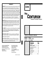
WARRANTY
WARRANTY: Except with respect to those components parts and uses
which are hereinafter described, Degussa-Ney Dental, Inc. (DegussaNey) warrants this furnace to be free from defects in material and workmanship for a period of two years from the date of sale. Degussa-Ney’s
liability under this warranty is limited solely to repairing or, at DegussaNey’s option, replacing those products included within the warranty which
are returned to Degussa-Ney within the applicable warranty period (with
shipping charges prepaid), and which are determined by Degussa-Ney to
be defective. This warranty shall not apply to any product which has
been subject to misuse; negligence; or accident; or misapplied; or
modified; or repaired by unauthorized persons; or improperly installed.
Q100
Ney
Vacuum Porcelain Furnace
INSPECTION: Buyer shall inspect the product upon receipt. The buyer
shall notify Degussa-Ney in writing of any claims of defects in material
and workmanship within thirty days after the buyer discovers or should
have discovered the facts upon which such a claim is based. Failure of
the buyer to give written notice of such a claim within this time period
shall be deemed to be a waiver of such claim.
DISCLAIMER: The provisions here-in stated Degussa-Ney sole obligation
and exclude all other remedies or warranties, expressed or implied,
including those related to MERCHANTABILITY and FITNESS FOR A
PARTICULAR PURPOSE.
LIMITATION OF LIABILITY: Under no circumstances shall DegussaNey be liable to the buyer for any incidental, consequential or special
damages, losses or expenses.
LIMITATION OF ACTIONS: The buyer must initiate any action with
respect to claims under the warranty described in the first paragraph
within one year after the cause of action has accrued.
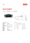
Owner & Operator's Manual
Model No:
94-93-928
94-93-929
Voltage:
100-120V 50/60Hz
230V 50/60Hz
DESCRIPTION
PAGE
Safety ........................................ 2
Installation .................................. 4
Corporate and Sales Office:
Degussa-Ney Dental, Inc.
65 West Dudley Town Road
Bloomfield, CT 06002-1316 USA
860.242.6188
FAX 860.769.5050
Product Service Office:
Degussa-Ney Dental, Inc.
Equipment Division
13553 Calimesa Blvd.
Yucaipa, CA 92399-2303 USA
909.795.2461
FAX 909.795.5268
Q100 9933 93-63-071
Getting Started ................... 6
Control Panel Description ......... 10
Specifications .......................... 13
Maintenance ............................ 15
Troubleshooting ........................ 18
Product Service ........................ 19
Accessories ............................. 19
Warranty .............................. Back
SAFETY:
!
• Never operate furnace in close proximity to combustible materials or
•
•
•
•
•
•
•
•
place materials on top of the furnace.
The furnace must be electrically grounded to a three wire electrical
outlet or receptacle. The electrical service provided must be a dedicated line of the proper size according to local electrical codes.
Disconnect the line cord before attempting to service the furnace.
Do not attempt to service the furnace until you read and understand the
service manual. (See Manual under Accessories on page 19)
Do not touch the reflective viewport window with fingers; the reflective
surface can be damaged by hand oils. Clean the window with a clean
soft dry cloth when furnace is in NITE MODE.
Do not operate the furnace controls with tongs or other tools; the tongs
will damage the control switches.
Do not use solvents or liquid cleaners on the control panel; they will
enter the panel and damage it.
Do not place firing trays or other hot objects directly in front of the
furnace; they will melt the graphic overlay.
Use only air, Nitrogen, CO2 and Argon for backfilling operations. Do not
use any other type of gas for backfilling.
OSHA AND CALIFORNIA PROPOSITION 65:
MUFFLE DUST EXPOSURE
In keeping with the policy of Degussa-Ney Dental, Inc. to build safe products, comply with
all National and State statutes and keep you, the valued customer informed; the services
of a Certified Industrial Hygienist firm were employed to test and evaluate the lab
operator’s exposure to respirable refractory ceramic fiber (RCF) and crystobalite (a form
of crystalline silica) present in the furnace muffle.
The findings of this test revealed that levels of exposure during the normal operation of
this equipment, as outlined in the operator’s manual, were far less than the Permissible
Exposure Limit set by the Federal Government.
When it becomes necessary to replace the muffle, the person doing this work is
recommended to wear a HEPA filter respirator and protective gloves as a precautionary
matter.
Seal used muffle in a plastic bag and dispose of in accordance with local, state and
Federal regulations.
Because this product and many similar products on the market today contain crystalline
silica and ceramic fibers, it is necessary under the statutes of California Proposition 65
that Degussa-Ney Dental, Inc. include the following statement:
“This product contains substance(s) known to the State of California to cause cancer.”
Material Safety Data Sheets for RCF materials supplied upon request.
Canadian Standards Association (CSA) and TÜV-GS certified.
2
ACCESSORIES:
DESCRIPTION
PART NUMBER
Tongs; 25cm (10") Stainless Steel
Tongs; 30cm (12") Stainless Steel
9390014
9390015
Vacuum Pump; 100-125V; 50/60Hz
Vacuum Pump; 220-250V; 50/60Hz
9492999
9492410
Side Mounted Work Shelf
Ceramic Side Platform Tray
Program Log Book
9492932
9390017
9364027
De-Con_Tam Kit; 5 carbon rods
Silver Calibration Coupons
Firing Tray Kit, 75mm (3") Round w/ pegs
Firing Tray Peg Kit (White)
Firing Tray Peg Kit (Black)
Firing Tray, flat 25mm sq (1"x1", 5 points)
9490799
9982561
9492969
9990042
9990043
9353047
Magnetic Language Information Cards
Ney
Magnetic Log Cards (pkg 5)
Service Manual, Q100
Call Degussa9492975
9363078
PRODUCT SERVICE:
Three methods of product service are available for the CENTURION. The first is telephone assistance available at the numbers listed below. The second is to return the
furnace for servicing using the instructions below. The final method is to call DegussaNey at the phone numbers below and obtain a service manual for a nominal fee.
BEFORERETURNINGTHEFURNACE,DOTHEFOLLOWING:
1. Remove all firing trays, work platforms, and other loose items from inside the muffle.
2. The original packing material should be used for the return shipment. Contact
Degussa-Ney for replacements if they are not available.
3. Call Degussa-Ney for a RMA number (Return Material Authorization). This is used to
track and identify your furnace. Material received without this number may not be
identifiable.
4. Equipment damaged in shipment as the result of improper packing may not be paid by
the carrier. The Degussa-Ney Dental, Inc. will not be responsible for damages
resulting from improper packing.
Ship Prepaid To:
Degussa-Ney Dental, Inc.
Equipment Division
909.795.2461
FAX 909.795.5268
RMA Number __________
13553 Calimesa Blvd.
Yucaipa, CA 92399-2303 USA
19
FEATURES:
TROUBLESHOOTING:
ERROR CODES:
Err codes can be cleared from the display by turning off and then on the
power switch if the error code was caused by a temporary condition.
Err 1: Over Temperature (Muffle temperature > 1220°C); Possible
causes: Shorted Thermocouple, shorted triac, shorted optotriac
on computer PCB, bad wiring connections, bad computer PCB
Err 2: Open Thermocouple (TC); Possible causes: Open TC tip, bad
connection to TC, bad TC to computer PCB connection, bad
computer PCB
Err 3: Over Temperature; Temperature above programmable limit Tmax;
Possible causes: Prog High Limit programmed lower than
current parameters, overshoot from high heat rate, same as Err1
Err 4: No Vacuum; Detected vacuum less than 40mm Hg; Possible
causes: Vacuum pump not connected (hose and power cord),
interference material on O-ring surface
Err 5: Lo Vacuum; Possible causes: moisture in muffle (run long cycle
with vacuum on), vacuum programmed higher than possible at
current location, poor vacuum pump performance, Press ESC to
clear the Err and continue the firing cycle
Err 6: Open Muffle: Little or no muffle current detected; Possible
causes: Open muffle, low line voltage, bad wiring connections,
bad triac
Err 7: Low AC Voltage; (Line voltage less than 80VAC or 160VAC)
Possible causes: wall socket shared with other loads, furnace
connected with small extension cord, low voltage from power
company
Err 8: EEPROM error; Microcomputer program memory error; Possible
causes: computer PCB
Err 9: Shorted or Reversed Thermocouple (TC); Possible causes: TC
connections reversed at computer board terminals, TC extension
wire shorted against metal structure or cabinet
Err 15: Motor too slow, time read up position is greater than 12 sec.
Possible causes: weight on top of enclosure, bent lift mechanism, control PCB failure
Err 18: Triac Driver Failure; Possible causes: Muffle or triac shorted.
Err 19: No line frequency detected; Possible causes: computer PCB
• 100 User Programs
• High Performance Quartz Spiral Muffle Produces Superior Porcelain with
Long Life Characteristics.
• Two Stage Programs for Controlled Tempering or Annealing
(Programs #80 - #100)
• Programmable Muffle Dry and Cooling Positions with Continuous Step
Movement During Dry and Cool Times
• 1204°C (2200°F) Maximum; 50°C (122°F) Minimum Temperature
• Ultra Smooth Muffle Movement with Stationary Work Support
•
•
•
•
Large Low Heat Loss Viewport
"Heat" Parameter Allows Work to be Preheated with Muffle Closed
Optimum Viewport Angle for Viewing Work Area
Large 10cm (4") Diameter Muffle
• Fast Cool Down for Short Times Between Loads Gives
Maximum Productivity
• Vacuum Release Programmable in Temperature or Time
• Fast Heat Rates of up to 222°C/minute (400°F/minute)
• Full Program Flexibility; Parameters Changeable During Firing Cycle
• Power Outage Return; Short Power Outages (<30seconds) Do Not
•
Interrupt Cycle Or Cause Loss of Vacuum Due To Outage
Programmable High Limit Temperature
• Ultra Friendly User Interface; Manual Not Required In Most Applications
• “i” Cards; Multiple Language Information and Help Cards
• Copy Program Key; User Can Copy and Edit Programs Rather Than
Enter ALL Parameters for EACH Program
• Energy Saver "Idle Down Time"; Programmable Timer Closes Muffle but
Maintains Lo Temp
• NITE MODE: Closes Muffle when Temperature Reaches 100°C to
•
Prevent Moisture Absorption
Automatic PURGE Cycle for Muffle Decontamination After the Use of
Silver Alloys
• Automatic Temperature and Vacuum Calibration; Operator Override
Available with Automatic Programs
• Agency Approvals: CSA, TÜV-GS, CE
• Insert Gas Backfill Capability with Adjustable Needle Valve
18
3
INSTALLATION INSTRUCTIONS:
UNPACKING:
Carefully unpack and remove the furnace from its shipping carton.
• Do not lift furnace by the top cabinet assembly.
• Save the carton and other packing material for future use
in transporting the furnace.
• Shipping damage should be reported to the carrier as
soon as detected.
The furnace shipping carton contains the following:
• One furnace complete with power cord
• Owner & Operator's Manual (this document)
• Side work shelf, Program log book and cards
• Vacuum tubing, connections, and fuses
• Ceramic work platform (MUST BE INSTALLED in furnace
before operation)
• Ceramic firing trays, ceramic pegs, and silver
coupons for temperature checks
IDLE DOWN TIME:
The length of time the furnace waits before closing the muffle when not
used can be programmed from 1 to 99 minutes. The time is set to 15
minutes when shipped from the factory. Programming the time to 0 turns
off this feature.
• Press the
(ENTER) key five times after turning on the power
switch to the furnace when the display initially shows "Setup?".
• The display will show the current programmed time. Use the digit
keys to enter a new time in minutes followed by the
key.
CLEANING:
• Vacuum dust and dirt from the furnace rather than blow. This will minimize
the amount of airborne dust particles.
• Use a soft damp cloth to clean the control panel. Avoid excess water or
solution when cleaning the furnace. These solutions can attack the panel or
electronics and cause the furnace to malfunction.
FUSES:
F1: F 250V / 1.0A;
F2: F 250V / 1.0A
INSTALLATION:
1. Remove all packing material from in and around the furnace. The
furnace should be located at least 15cm (6") away from walls, shelves
and heat sensitive materials.
2. The furnace should not be located directly under shelves or other airflow
restrictions.
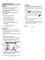
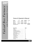
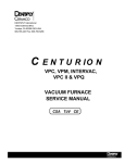
3. ELECTRIC VACUUM PUMP CONNECTIONS:
From the rear of the furnace connect the vacuum pump's tubing to
point B and plug the pump's power cord into the socket at point A
(use separate pump adaptor cord on 230V models).
Rear View Of Furnace
Vacuum
Pump A
Socket
Manual (Emergency)
Vacuum Release
and gas backfill port
External
Vacuum
Pump Connection
B
Power
Cord
C
4. Connect the furnace to a power circuit or receptacle with an overcurrent
protection (circuit breaker or fuse) rating of at least 20 Amps. This
circuit should only supply the furnace and pump.
5. Turn on the furnace power switch (right-hand side of the control panel).
4
17
7. To check press the
ENTER key when the display shows
"Setup?" after power is turned on.
PROGRAMMABLE HIGH LIMIT TEMPERATURE:
The user can program a high limit temperature that is lower than the
fixed limit of 1204°C built into the control. This limit will cause the
furnace to go into Err3 if the muffle temperature exceeds this value.
(ENTER) key twice after turning on the power
1. Press the
switch to the furnace when the display initially shows "Setup?".
2. Enter the digits keys of high desired high temperature followed by
the
key and the E S C key.
VACUUM ADJUSTMENT:
The 100% vacuum level can be adjusted if the furnace is being operated at
a high elevation or with a weak vacuum pump. The Vcal should be
reduced for higher elevations by subtracting 80mm per 1000m from the
maximum of 740mm at sea level. (1" for every 1000' from 29")
1. Turn on power switch. When "Setup?" is displayed, press the
key three times. Display shows "beep on".
2. The display will show the current vacuum setting "Vac Cal"
"100%=710mm".
3. Enter the new Vcal value followed by the
key. The furnace
is now recalibrated to the new value. Press the E S C key to leave
the Setup routine.
OR
• The "Vac Cal" maximum value can be established by running
program 102. This cycle takes about 1 hour and stores the max
vacuum valve into the setup routine at the end of the hold time
automatically. Check by following step 1 above.
OR
• The maximum vacuum possible can be checked by programming a
long hold time with the VAC set to 101%. This will cause the
vacuum pump to run continuously. The maximum vacuum appears
on the LCD display. Enter this new value for 100% vacuum in step 3
above.
Beep ON/OFF
• Turn on power switch. When "Setup?" is displayed, press the
key four times. Display shows "beep on". Press 1 followed by the
enter key to turn off beep function. Press E S C to leave
setup routine.
16
6. The furnace display will show "Nite Mode", "Test f=60Hz" and "AC+
xxx" after approximately 8 to 10 seconds of self test.
7. FIRST TIME ONLY: After the initial power up the display will show:
"Remove Bag!" and "Place Insulation". The muffle will open and the
display will change to "To Operate: <ESC>" and "* Muffle Off *" Pressing the E S C key will start normal operation.
If the operation of the furnace causes the lights to "blink" or "flicker"
change to new circuit. The furnace is on the same circuit breaker/fuse
as the lighting.
8. IMPORTANT! Open up furnace with muffle movement keys located on
lower left side if the furnace does not open automatically. Install
ceramic work platform ("Place Insulation").
Operating the furnace without this platform will damage the furnace!
S start key in the upper
9. Press E S C key followed by the (green)
right corner of the control panel. Program 50 will now run to remove
any accumulated moisture. This program will take approximately 1/2
hour.
If the furnace does not pull vacuum "Err4" press the (red) S
key
and stop the cycle. Check the following:
• Verify that the ceramic work platform is centered on the door.
• Check the vacuum pump to verify that it is energized.
• Check the vacuum hose connections to verify that they are
connected to the correct locations.
• Verify needle valve C on rear is closed.
If the furnace pulls a low vacuum "Err5" there may be moisture in the
muffle. Press the E S C key and allow the furnace to continue running
to remove the moisture. If the furnace is being operated at a high
altitude the Vac Cal may require an adjustment. Run program #102 to
adjust the vacuum calibration. (See page 16)
10. Daily Use: Before starting the normal firing process each day allow the
furnace to preheat for 15 to 30 minutes at its low temperature. Alternately, running a firing cycle without a load can also be used as a
preheat operation. Preheating the furnace will provide more accurate
and consistent results.
When the furnace is not being used keep the muffle closed. This
prevents the absorption of moisture into the thermal insulation which
reduces vacuum levels when normal firing is attempted.
5
OPERATING INSTRUCTIONS:
CHANGING PROGRAMS:
The current program number is displayed in the upper right-hand corner of
the display window. The program number can be changed when not
running a program (No red LED's are turned on).
Example: Change to program 34.
Key sequence: 3 4
STARTING PROGRAMS:
Press green Start S key to start current program. Pressing the red
Stop S key during a cycle or program stops or aborts the program.
When a firing cycle is started all of the parameter LED's light (VAC
LED's also light if vacuum is on). The second line of the LCD display
shows the current cycle segment and the approximate time remaining
in the firing cycle. If the cycle is a vacuum cycle the "Vac" in the top
line of the display is replaced by "0mm" or "0in" for the readout of
vacuum level.
The LED's turn off as the associated cycle segment is completed.
The LCD displays the current cycle segment name and the approximate time remaining.
CHANGING PROGRAM PARAMETERS:
Press one of the
parameter keys followed by the digit keys
and
(ENTER) key to change a parameter of the current
program. Each time the key is pressed the next parameter in the
sequence is activated.
"Lo T" for low temperature, "Rate" for ramp rate, and "Hi T" for high
temperature. The LED for the selected parameter is turned on when
selected. For "T2" see special operations sections.
"Dry" for dry time, "Heat" for preheat time, "Hold" for hold time, and
"Cool" for cool time. For "H2" see special operations sections.
"Vac" for vacuum level, "Pull" for vacuum start temperature, and
"Stop" for vacuum stop temperature and stop time.
Pressing the keys additional times simply cycles the display through
the parameters again. The selected parameter remains active for
approximately 60 seconds and then the display changes back to an
idle mode. Press the E S C key to change the display sooner.
VAC
VAC
6
SETUP & MAINTENANCE:
The CENTURION has a software adjustment program for changes in operation.
It is called "Setup". The following procedure identifies how to use the "Setup"
routine to make these types of changes.
The furnace displays "Setup? " after it's internal testing when power is turned
on. If the
(ENTER) key is pressed when the word "Setup?" is displayed
the furnace will go into an operator "Setup" routine. In this routine various
control characteristics can be reviewed and changed. These include: Temperature Adjustment, Programmable High Limit Temperature, Vacuum
Adjustment, Beep on/off, and Idle Down Time.
TEMPERATURE ADJUSTMENT:
Every CENTURION is calibrated at the factory to 960°C +/- 3°C. This calibration
will not drift with time or firing cycles beyond this range. This accuracy applies
to furnaces that are temperature stabilized (i.e., furnace has operated at the Lo
T for a minimum of 20 minutes).
Silver calibration is not recommended due to its poor accuracy. Silver
calibration under ideal conditions is only accurate to +/- 10°C. If not done
correctly, a +/- 25°C error is possible.
The Tcal setup feature allows the operator to adjust for temperature differences
between materials and techniques. If consistent overfiring is occurring, the
Tcal value should be reduced by the estimated number of degrees that it is
overfiring. The estimated number of degrees that the furnace is underfiring
should be added to the Tcal value. If the furnace is estimated to be over firing
by 15°C then subtract 15 from 960 which results in 945. 945 is entered into the
Tcal value replacing the 960. Procedure:
1. Press the
(ENTER) key when the display shows "Setup?" after
power is turned on.
2. Enter the desired Tcal value followed by the
key.
3. Press the ESC key to exit Setup.
The furnace can be reset to the factory calibration by setting the Tcal value to
960°C. Changes in the Tcal value affects all temperature and programs.
If a silver calibration must be done, use the following procedure:
1. Set the cal. to 960°C (see above).
2. Preheat the furnace by running several firing cycles that heat to 960°C.
3. Place the silver on a firing tray that was preheated. Silver should have
minimum contact with the tray and be at the normal working height.
4. Change to program 101. This is a preprogrammed cycle for doing silver
calibrations. Press the (green) S
to start the cycle.
5. Observe the silver coupon, when it starts to change appearance, the
temperature reached 960°C.
S
6. Press the (red)
key to stop the cycle. This will automatically store
the new Tcal valve into the setup routine.
15
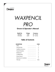
TEMPERATURE PARAMETERS:
Example: Change rate to 140°C/Min.
Key sequence: E S C
1
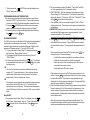
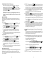
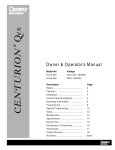
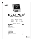
PERFORMANCE CURVE (maximum ramp rate)
1200
1100
0
The E S C key is optional. If not used the number of times the parameter
HEAT RAMP
1000
TEMP (DEG C)
4
key must be pressed will vary depending on the previous keys
pressed.
900
Parameter values programmed or changed during a firing cycle are
used only during the current cycle and are not stored permanently in
memory. Parameters in a firing cycle that have already been started
will not be changed or affected.
800
700
COOL DOWN
600
The Specifications Parameter Table (page 13) lists the allowable
ranges for the various parameters. Attempts to enter values outside
the allowable limits will cause the furnace to beep, display the limits
and revert back to the original value.
500
400
300
0
2
4
6
8
10
12
14
16
TIME (MINUTES)
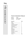
OUTLINE DRAWING:
in (mm)
11.5 (292)
14.5 (368)
11.6 (295)
10.5 (267)
7.1
(180)
13.1
(333)
TIME PARAMETERS:
Example: Change cool time to 3 minutes and 40 seconds (program 1-79).
Key sequence: E S C
0
3
4
13.0 (330)
SYMBOL TABLE
- Alternating current
I - On (Supply)
O - Off (Supply)
- Hot Surface
Protective
Conductor Terminal
"Lo T" LOW TEMPERATURE is the initial or starting temperature parameter.
"Rate" TEMPERATURE RAMP RATE is the temperature increase parameter in degrees per minute.
"R2" (programs 80-100 only) This is displayed during the transition from
the "Hi T" to "T2". This rate is not programmable for cooling and uses
the first "Rate" for heating parameters.
"Hi T" HIGH TEMPERATURE is the final or last temperature parameter
where the furnace ends the firing cycle.
"T2" SECOND HIGH TEMPERATURE (programs 80-100 only) is the
second final or last temperature parameter where the furnace ends
the firing cycle. The same "Rate" is used. "T2" can be higher or
lower than the "Hi T". See "TWO STAGE OPERATIONS" later in this
section.
19
(483)
6.0 (153)
5.9 (150)
17.4 (442)
14
"Dry" TIME is the parameter for the time period between the start of the
cycle and the muffle closure. The muffle closes to the programmed
position then moves to the fully closed position using multiple small
steps in the programmed dry time.
"Heat" is the parameter for the time period that the muffle will hold the LoT
with the chamber closed.
"Hold" is the parameter for the time period that the muffle is held at the
high temperature.
1.6 (41)
7
OPERATING INSTRUCTIONS (cont)
"Cool" is the parameter for the time period from the end of the "Hold" time
until the muffle is completely open. At the end of the "Hold" time the
muffle opens in multiple steps from fully closed to the programmed
"Cool" position.
"H2" (programs 80-100 only) is the parameter for the second time period
that the muffle is held at the second high temperature "T2". See
"TWO STAGE OPERATIONS" later in this section.
VACUUM PARAMETERS:
Example: Change VAC level to 100%.
Key sequence: E S C
0
1
VAC
0
"Vac" VACUUM LEVEL is programmed in percent of the total available
vacuum. The vacuum is turned off by programming the level to 0%.
The maximum vacuum is achieved by programming the level to 100%
and the minimum by programming to 10%. In special cases where it
is desired that the pump run continuously when vacuum is programmed on, the level must be set to 101%.
"Pull" is the vacuum start temperature parameter. This controls the
temperature at which vacuum is applied. This should be programmed
equal to or lower than the "Lo T" in most applications.
"Stop" is the vacuum stop temperature and time parameters that stops or
turns off the vacuum. Normally this parameter is programmed higher
than the "Hi T" so that the vacuum is held during the full cycle.
Programming this lower than the "Hi T" will stop the vacuum during
the temperature ramp at the programmed temperature.
For the vacuum to be held for only a portion of the "Hold" time the
vacuum "Stop" temperature must be set equal to the "Hi T" temperature. The furnace will then ask for a vacuum stop time which can be
programmed from 0 to a value equal to the current "Hold" time. The
factory setting is 1:00 minute. The vacuum "Stop" time does not
affect the length of time the muffle is held at the "Hi T".
SPECIAL OPERATIONS:
COPY - Press the COPY key. The second line of the display will
prompt for a new program number to copy the current program contents to.
Example: Copy current program parameters to program 73.
Key sequence: COPY
7
3
Program 73 will now contain an exact copy of the original program
parameter.
8
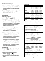
SPECIFICATIONS:
PARAMETER
Low Temperature
Dry Time
Heat Time
Heat Rate
High Temperature
Hold Time
Vacuum Level*
Vac Pull Temperature
Vac Stop Temperature
Vac Stop Time
Cool Time
MINIMUM
50°C (122°F)
0 Seconds
0 Seconds
1°C/Min.
(2°F/ Min.)
50°C (122°F)
0 Seconds
10%
50°C (122°F)
50°C (122°F)
0 Seconds
0 Seconds
MAXIMUM
INCREMENT
800°C (1472°F)
1°C (1°F)
99:59 Min.
1 Sec
99:59 Min.
1 Sec
222°C/Min.
1°C/min.
(400°F/ Min.)
(1°F/min.)
1204°C (22 °F)
1°C (1°F)
99:59 Min.
1 Sec
100%
1%
1204°C (2200°F) 1°C (1°F)
1204°C (2200°F) 1°C (1°F)
Full Hold Time
1 Sec
99:59 Min.
1 Sec
* Special Vacuum Cases: 0% is no vacuum or air firing cycle; 100% is the
maximum vacuum possible at current location; 101% is pump on continuously
during the programmed vacuum on time.
OPERATIONAL
- Temperature Accuracy:
+/- 3°C (+/- 5.5°F) at steady state
- Muffle Temperature Uniformity: +/- 5°C (+/- 9°F) at steady state
- Vacuum Recycling Dead Band: 30mm Hg
- Muffle Temperature In NITE MODE: 100°C +/- 10°C
ELECTRICAL
Voltage Ranges:
100-120V
230V
50/60Hz
50/60Hz
Currents:
13 Amps @ 100V
10.8 Amps @ 120V
5.7 Amps @ 230V
Wattage: 1300 Watts (less pump) Steady State
[1800 W during ramp-up cycle]
Watts to Maintain 1000°C: less than 400 Watts, muffle closed,
no vacuum pump
MECHANICAL
Exterior Dimensions:
Height
Muffle open
48cm (19")
Muffle closed
33cm (13")
Interior Muffle Dimensions:
Height: 6.3cm (2.5")
Furnace Weight: 21Kg (45lbs)
Width
33cm (13")
33cm (13")
Diameter: 10cm (4")
Shipping Weight: 25Kg (55lbs)
ENVIRONMENTAL
Ambient Operating Temperature: 5 - 40°C
Relative Humidity: Maximum 80%, non-condensing
13
Depth
45cm (17.5")
41cm (16")
OPERATING INSTRUCTIONS (cont)
carbon rod into the muffle in the horizontal position. Change the
program number to 0 and then press the
key. The Purge
Cycle starts automatically when the
key is pressed. Pressing
the (red) S key stops the cycle. A complete purge cycle lasts
approximately 2 hours.
CAUTION: Do not stop this cycle at elevated temperatures, the
release of vacuum can damage the muffle and cause an unsafe
condition.
MUFFLE POSITION:
The "DRY" and "COOL" positions can be adjusted for each furnace. To
change the factory preset "DRY" or "COOL" positions, use the following
procedure:
"DRY" Position:
1. Press 2 4 6 keys followed by the
(ENTER) key. The
furnace will display "DRY POSITION --_" while calibrating itself.
2. Press the
keys so that the muffle moves to the
desired position followed by the (ENTER)
key.
3. The muffle will then move up and then down to confirm the new
programmed position. This will be the "DRY" position for all programs.
4. During the Dry time the muffle will close in multiple small steps from
the programmed height to the fully closed.
"COOL" Position:
1. Press 1 3 5 keys followed by the (ENTER)
key. The
furnace will display "COOL POSITION _--" while calibrating itself.
2. Press
the keys so that the muffle moves to the
desired position followed by the (ENTER)
key.
3. The muffle will then move down and then up to confirm the new
programmed position. This will be the "COOL" position for all programs.
4. During the Cool time the muffle will open in multiple small steps from
fully closed to the programmed height.
Manual Muffle Positioning:
The muffle can be manually position during the DRY and COOL portions of
the firing cycle by using the muffle movement keys during DRY and/or
COOL. The furnace will remain in the position and not until the dry or cool
time has elapsed.
12
NEXT STEP - Pressing the key
during a firing cycle will cause
the control to end the current cycle segment and move on to the next.
(e.g. Rate > Hold > Cool) Pressing this key during the Cool segment
will cause the furnace to repeat the last cycle starting with the Rate.
ESC - Pressing the E S C key during programming will return the furnace
to the IDLE MODE or FIRING CYCLE MODE if the furnace was
running a cycle.
NITE - Pressing the
key will cause the furnace to go into NITE
MODE if the furnace is in IDLE MODE. The furnace will cool down to
100°C and the muffle will close. If the furnace is in a firing cycle when
the key is pressed, the furnace will go into NITE MODE after the cycle.
Press the E S C key or one of the parameter keys to cancel or abort
the NITE MODE.
MUFFLE MOVEMENT
- Pressing the up or down key will
move the muffle in the indicated direction until it reaches its full travel.
Pressing the key while the muffle is moving will stop the muffle at its
current position. See page 12 for muffle movement during the DRY
and COOL portions of the firing cycle.
°C / °F Key changes the display from Celsius to Fahrenheit and back.
The conversion can not be done during parameter programming. The
measurement units for vacuum also changes from "mm Hg" to "in Hg"
when the temperature units are changed.
TWO STAGE OPERATIONS - Programs 80 through 100 have a second
"Hi T" or high temperature ("T2") and "Hold" time ("H2") that allow
for special operations such as tempering.
Example: Program "T2" to 850°C.
LoT RATE R2 HiT
Key sequence: E S C
8 5 0
Example: Program "H2" to 2 minutes and 0 seconds.
DRY HEAT HOLD H2
Key sequence:
2
0
0
"T2" can be programmed lower or higher than the corresponding
"Hi T".
PURGE CYCLE: Program "0" is the automatic purge cycle. Load the
9
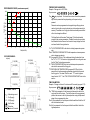
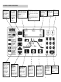
CONTROL PANEL DESCRIPTION:
COPY Press key
followed by digit
keys and ENTER to
copy current
program parameters
to new program.
°C/°F
changes
the temperature
and vacuum units
from °C/(mm) to °F
(in) and back. This
key is not active
during parameter
programming.
NEXT STEP causes the
control to go to the next step
(segment) of the current
firing cycle.
e.g. Hold >> Cool
LCD Display shows muffle
temperature; "Air" or "Vac" (mm or In
of Hg during cycle); current program
number.
Second Line displays current status
and cycle time which counts down
during cycle.
1010°C
70Omm
HOLD
ESC exits Nite Mode.
If pressed during
programming exits to
IDLE MODE.
starts STOP Stops
current cycle or or aborts program
if already operating.
program.
START
100
3:21m
NITE MODE puts
the furnace into NITE
MODE (muffle is
held at 100°C and
muffle closes). If
pressed during a
cycle, the furnace
goes into NITE
MODE at the end of
the cycle.
MUFFLE
MOVEMENT
KEYS open and
close the muffle.
Pressing it a
second time during
movement causes
the muffle to stop.
10
TEMPERATURE
KEY access to
program or review 3
temperature parameters: Low Temp;
Ramp Rate; and High
Temp(s).
TIME KEY
VACUUM KEY
Digit KEYS used
access to program
or review 4 timing
parameters: Dry
Time; Heat, Hold
Time(s); and Cool
Time.
access to program or
review 3 (4) vacuum
parameters: Vacuum
Level; Vac Pull (start)
Temp; and Vac Stop
Temp (stop time).
to enter program
numbers, parameters and purge
cycle.
11
ENTER KEY used
to store new program
number or parameter
in memory.