1
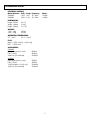
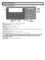
PROCESSING UNIT II
Owner & Operator’s Manual
Model No.
Voltage
Frequency
120V
230V
50 – 60 Hz
50 – 60 Hz
9494800
9494801
Table of Contents
DESCRIPTION
Safety
PAGE
2
Technical Data
3
Installation Instructions
4
General Operation
5
Maintenance
11
Troubleshooting
15
Product Service
17
Declaration of Conformity
18
Warranty
20
1
SAFETY:
FOR PROFESSIONAL USE ONLY.
Please read these operating instructions carefully before installing or operating this equipment.
Use indoors only.
Never operate the unit in close proximity to combustible materials or place materials on top of the unit.
The unit must be electrically grounded to a three wire electrical outlet or receptacle. The electrical service provided must
be a dedicated line of the proper size according to local electrical codes.
Unit must be placed in a position that allows the power cord to be easily disconnected from the wall or inlet socket.
Do not attempt to service the unit until you have read and understand this operation manual.
Turn off the power switch and disconnect the line cord before attempting to service the unit.
Do not operate the unit controls with tongs or other tool.
Do not use solvents or liquid cleaners on the control panel.
Do not touch the bulbs when the unit door is open.
Before replacing bulbs, allow the unit to cool to room temperature to avoid burns.
Do not cover the top of the unit or obstruct the rear fans in any other way.
Do not heat water or food in the unit chamber.
Do not submerge the unit into any liquid.
Do not store flammable products or solvents inside the unit chamber.
If the unit is not operated in the manner as specified in this manual, the protection provided by the unit may be
impaired.
!
CAUTION: RISK OF DANGER! BURN HAZARD IS PRESENT WHEN COVER IS OPENED.
USE CAUTION AFTER OPENING COVER, BULBS AND METAL SURFACES MAY BE HOT!
USE HEAT RESISTANT GLOVES WHEN REMOVING BULBS!
SYMBOL TABLE
- Alternating current
I
- On (Supply)
O
- Off (Supply)
- Caution, Hot Surface
- Protective Conductor
!
- Caution, Risk of Danger
2
TECHNICAL DATA:
ELECTRICAL RATINGS:
Model Number Volts Amps Frequency
9494800
120V 10A
50 - 60Hz
9494801
230V 5.2A 50 - 60Hz
DIMENSIONS:
Length: 510mm
Width: 366mm
Height: 385mm
(20.1”)
(14.4”)
(15.15”)
WEIGHT:
120V: 25kg
230V: 25kg
(55 lbs)
(55 lbs)
Watts
1200W
1200W
OPERATING TEMPERATURE:
5°C – 40°C
(41°F – 104°F)
FUSE:
Mains: F 250V 10A (2) – (230V only)
PCB: T 250V 4.0A
ACCESSORIES:
9494800
Bulb, Replacement (1 each)
Filter (1 each)
4.0A Fuse (Circuit Board)
905032
905034
9320055
9494801
Bulb, Replacement (1 each)
Filter (1 each)
10A Fuse (Mains – 230V only)
4.0A Fuse (Circuit Board)
905032
905034
9320069
9320055
3
INSTALLATION INSTRUCTIONS:
Shipping damage should be reported to the carrier as soon as detected.
The Unit Package contains the following:
Owner & Operators Manual (this document)
Eclipse Processing Unit w/Power Cord
2 Spare Bulbs
Turntable
Gloves (1pr.)
10A Fuse (2) - (230V only)
4.0A Fuse (1)
UNPACKING:
Save the box and other packing material for future use in transporting the unit.
Open the box.
Carefully lift the unit from the box by lifting on packaging supports. Support unit from the bottom to prevent slipping.
Remove packaging supports.
Remove plastic bag.
INSTALLATION:
Open the box.
Remove accessory kit.
Carefully lift the unit from the box by lifting on packaging supports.
Remove packaging supports.
Remove plastic bag.
Remove remaining packing material on outside of unit.
Remove turntable from the top of unit.
Lift unit from packing supports by metal base only. DO NOT LIFT UNIT USING PLASTIC SIDE COVERS.
Carefully place the unit on a solid flat surface. Position the unit at least 10cm (4 in) from the wall or other structures to
allow for good airflow.
Connect unit to a grounded power source.
Open door and install turntable onto motor shaft, match flat sides of shaft and turntable.
WARNING:
Never operate the Unit in close proximity to combustible materials or place materials on top of the unit.
Do not use extension cords with this equipment.
Plug the power cord into a circuit rated a minimum of 15A.
Do not position the unit in a way that blocks access to the power cord inlet socket or the wall outlet.
4
GENERAL OPERATION:
FUNCTION KEY DESCRIPTIONS:
CARD
READER
ESC
DISPLAY
ON / OFF
CURSOR PROG
DOWN
START/STOP
CURSOR
UP
LIFT
(UP/DOWN)
ESC Key: Aborts changes, exits menus and clears errors on the screen.
CURSOR DOWN Key: Moves cursor on menu - down
PROG Key: To view process parameters.
CURSOR UP Key: Moves cursor on menu - up
START/STOP Key: START or STOP the selected process. Press once to confirm the process name, lamps used and cycle
time. Press again to start the process.
LIFT (up & down) Keys: Raise and lower the work platform.
DISPLAY ON/OFF Key: Turns display ON & OFF. Unit is in standby when “OFF”.
!
THIS DOES NOT DISCONNECT ELECTRICAL POWER. DO NOT ATTEMPT TO SERVICE THE UNIT. FIRST
TURN OFF THE POWER SWITCH AT THE REAR OF THE UNIT AND UNPLUG THE UNIT FROM THE
ELECTRICAL SOURCE.
CARD READER: Used to load new material programs
5
GENERAL OPERATION: Cont.
POWER UP:
The power switch is located on the rear of the unit, as shown.
Turn the power switch to the ON position, as shown.
Power Switch
Circuit Breaker
(12A)
AC Power Cord
AC Power Inlet
(230V UNIT)
(120V UNIT)
The display will turn on and a language screen will be displayed for a short period of time. This screen will change to the
process menu automatically.
LANGUAGE SELECTION:
There are five languages available: English, German, French, Italian and Spanish.
The language selection screen can be accessed at power up or by pushing the ESC key once when viewing the process
menu. If no selection is made within 5 seconds the unit will default to the process menu.
LANGUAGE SELECTION SCREEN
To select a language, use the Cursor Up & Cursor Down keys adjacent to the display within 5 seconds. Once the preferred
language is highlighted, the 5 second timer will reset, wait 5 seconds to allow the unit to change to the process menu with
the new language choice.
6
GENERAL OPERATION: Cont.
When the unit is turned on by means of the power switch a diagnostic test is performed to check the operation of key
systems in the unit. The screen shown below will be displayed. If a problem exists an error will be displayed. Reference
errors in the troubleshooting section of this manual.
INITIAL DIAGNOSTICS CHECK SCREEN (DOOR MUST BE CLOSED!)
After a successful diagnostics test the process menu will be displayed.
SELECT PROCESS
Use up/down cursor keys to select process, press PROG.
PROCESS MENU SCREEN
Use the up/down cursor keys to select a process, press PROG.
7
GENERAL OPERATION: Cont.
Once a process is selected, push the PROG key or the START/STOP key to confirm the Process Parameter Screen.
PROCESS PARAMETER SCREEN
This screen shows the name of the process selected, the number of lamps used and its cycle time (cooling time can be set
from 30 seconds to 5 minutes).
To return to the Process Menu press the ESC key or wait 15 seconds. The screen will return automatically to the main menu.
A timer is displayed at the bottom of the screen indicating how much time is left to start the process.
To run this process the START/STOP key must be pushed again.
Once started, the running process screen is shown.
PROCESS RUNNING SCREEN
The process will run for the length of the processing time displayed. The unit will pause at end of process to check table
rotation; a long beep indicates the start of the cooling phase. Remove the work and allow unit to cool.
!
CAUTION: Models may still be hot - Use caution when removing materials from chamber.
8
GENERAL OPERATION: Cont.
COOLING SCREEN
Once cooling is completed the display will return to the process menu. The last process used will again be highlighted on
the process menu.
ABORT PROCESS:
When the START/STOP key has been pressed during a process, the following screen is shown to confirm the aborting of the
process.
ABORT PROCESS SCREEN
ESC cancels the abort command.
ABORT PROCESS COOLING SCREEN
If START/STOP was pushed or the door was opened during the process, a long beep will be heard and the cooling screen
above will be shown.
Remove work and allow the unit to cool.
!
CAUTION: Models may still be hot - Use caution when removing materials from chamber.
9
GENERAL OPERATION: Cont.
LOADING CARD PROGRAMS
From this screen, insert card with label facing up.
Press the PROG key to load data.
Program loading.
Program loaded, remove card. Display will return to Select Process.
10
MAINTENANCE:
WARNING:
This equipment contains dangerous voltages. Maintenance and repair work should only be performed by an
authorized service technician of DENTSPLY Ceramco.
To keep the equipment in good working order you should follow the guidelines below.
Examine the equipment regularly for mechanical damage.
Make sure the lift is not obstructed in any way.
Do not overload the table (1lb. max), this can cause the motor to turn slower and cause wear on the bearings.
Do not use solvents or liquid cleaners on the control panel; they could enter the panel and cause damage.
Do not attempt to manually force the lift when unit is powered up. This may result in motor damage.
CLEANING:
Clean the unit at least once a week.
Clean exterior surfaces with a soft, damp cloth using a mild detergent and water.
DO NOT IMMERSE IN WATER!
Clean the fan and exhaust vents, using low pressure compressed air, once a month or as needed to prevent
overheating.
BULB AND FILTER REPLACEMENT: (USER MAINTENANCE)
!
!
CAUTION:
TURN OFF THE POWER SWITCH AND UNPLUG UNIT FROM WALL BEFORE
PERFORMING ANY MAINTENANCE ON THE UNIT.
CAUTION:
RISK OF DANGER! BURN HAZARD IS PRESENT WHEN COVER IS OPENED.
USE CAUTION AFTER OPENING COVER, BULBS AND METAL SURFACES MAY BE
HOT! ALLOW TO COOL AT LEAST 15 MINUTES BEFORE CHANGING. USE HEAT
RESISTANT GLOVES WHEN REMOVING BULBS!
NOTE: IT IS PREFERRABLE TO ALLOW THE UNIT COOL COMPLETELY BEFORE REPLACING BULBS TO
ELIMINATE BURN HAZARDS.
When a lamp is burned out, its location number will flash on the display. In the picture below, L2 is burned out. Follow the
instructions on the next page to replace it with a new one.
11
MAINTENANCE: Cont.
1. Turn the power switch OFF.
2. Unplug the power cord.
3. Loosen two screws on rear of top panel.
4. Slide top panel backwards until full access to
bulbs is achieved.
5. Put supplied gloves on hands.
6. Loosen center bulb bracket retaining screws, if
needed, for bulb clearance.
Front of unit
Loosen 2 screws by hand.
!
Failure to wear gloves could cause premature lamp failure due to skin oils.
7. Place center bulb bracket in slots on left side of internal cover. Be careful not to remove the filters in the bracket. Do not
touch the filters with bare hands, handle with gloved hands only. If filters are being replaced, the filters have a frosted
side and a shiny side. The frosted side should be placed toward the lamp. ABSOLUTELY NO SUBSTITUTE FILTERS MAY
BE USED.
Frosted Side UP!
12
MAINTENANCE: Cont.
8. Push the bulb release lever far enough to loosen
the bulb from the socket.
9. Remove bulb.
10. IMPORTANT! Return the bulb release lever to
forward position.
11. Insert new bulb. Retaining spring should slide
over bulb.
12. Reinstall the center bulb bracket, tighten retaining
screws.
13. Close cover, secure with 2 screws.
Tighten 2 screws
14. Plug unit in.
15. Turn on power switch.
13
MAINTENANCE: Cont.
FUSE REPLACEMENT (230V UNITS ONLY):
Mains - located in the rear of the unit inside the inlet socket.
1. Turn the power switch OFF
2. Unplug the unit.
3. Remove fuse drawer from inlet socket (contains 2 fuses)
using small screwdriver to push on the locking clip.
4. Remove fuse drawer.
5. Replace fuse(s) with the F 250V 10.0A fuse(s) (supplied).
6. Push fuse drawer into inlet socket until the clip locks.
7. Plug Unit in.
8. Turn on Power Switch.
14
TROUBLESHOOTING:
NO TABLE ROTATION OR TABLE IS NOT IN THE DOWN POSITION AT THE START OF THE PROCESS.
ERROR 1
Indicates table rotation was not detected, or table is not in the down position at start of menu.
Make sure the table handle is pushed completely forward and the lift is in the DOWN position, then push ESC. If the
lift is still elevated, turn OFF the unit, open the door and gently push the table down to the stop position. Turn the unit
ON.
Call DENTSPLY service department if problem persists.
OVER TEMPERATURE
ERROR 2
The temperature of the unit has exceeded the maximum temperature allowed.
Turn unit off then on.
Check blower operation.
Check fan operation.
Call DENTSPLY service department if problem persists.
BULB FAILURE
ERROR 3
One or more bulbs failed.
The bulb layout seen on the display is the same as arranged in the unit, as viewed from the top.
The failed bulb will blink on the display.
Follow the bulb replacement procedure.
Call DENTSPLY service department if problem persists.
15
TROUBLESHOOTING: Cont.
LIFT OPTICS
The horizontal light beam was not detected to stop lift.
Make sure that nothing is obstructing the lift and the lift in the down position.
Call DENTSPLY service department if problem persists.
POWER FAILURE
AC line power was lost during a process.
Push ESC to return to the main menu.
CLOSE DOOR
START/STOP was pushed with the door open.
Once the door is closed the display will return to the process menu screen.
If the door is closed, the door switch may be malfunctioning,
Call DENTSPLY service department if problem persists.
16
PRODUCT SERVICE:
WARNING:
This equipment is designed with safety features to protect the operator and must not be modified in any form. Only
qualified individuals should repair this piece of equipment. Failure to observe these precautions may result in burns
or electrical shock.
Three methods of product service are available:
Telephone assistance available at the number listed below,
Return the unit for servicing using the instructions below,
Call DENTSPLY at the phone number below and obtain a service manual for a nominal fee
BEFORE RETURNING THE UNIT:
Call DENTSPLY for an RMA (Return Material Authorization) number. This is used to track and identify your unit.
Equipment received without this number may not be identifiable.
Equipment damaged in shipment as a result of improper packing may not be paid by the carrier.
DENTSPLY will not be responsible for damages resulting from improper packing.
Ship prepaid to:
DENTSPLY Ceramco
DENTSPLY International
RMA Number ________________
13553 Calimesa Blvd.
Yucaipa, CA 92399-1203 USA
Phone: 909.795.2461
Fax:
909.795.5268
[email protected]
Our European Representative is:
DeguDent GmbH
Rodenbacher Chaussee 4
D-63457 Hanau
Germany
Phone +49 6181 59 57 59
Fax
+49 6181 59 59 62
Disposing of the device:
The device is an electronic device according to the “Act Governing the Sale, Return and Environmentally Sound
Disposal of Electrical and Electronic Devices” (ElektroG).
It was identified in accordance with the existing law and provided with this symbol.
The device is not intended for private use. It is manufactured and delivered for commercial use and is to be disposed
by the end user according to the specifications of the Electrical and Electronic Equipment Act – ElektroG.
17
DECLARATION OF CONFORMITY:
13553 Calimesa Blvd.
Yucaipa, CA 92399
USA
Dentsply Ceramco certifies that the following product:
Names: Eclipse Processing Unit (EPU II) Light Curing Unit
Serial Numbers: JJA/JJE xxxx-xxx (Where x is a number from 0-9)
Conforms with the basic requirements of the following EC guidelines:
- Low Voltage Directive 73/23/EEC
with 1. Modification 93/68/EEC
- EMC Directive - 89/336/EEC Electromagnetic Compatibility
with 1. Modification 92/31/EEC
2. Modification 93/68/EEC
- Machinery Directive 98/37/EC Safety of Machinery – Basic concepts, general principles for design
- RoHS Directive 2002/95/EC Regulation of Hazardous Substances (Lead, Mercury, Cadmium, Hexavalent
Chromium. Polybrominated Biphenyls ((PPBs), or Polybrominated Diphenyl Ethers (PBDEs),
The regulated hazardous substances have been eliminated or controlled to the specified
concentrations of 0.1% for materials listed above except for Cadmium which is specified at 0.01%.
- WEEE Directive 2002/96/EC Waste from Electrical and Electronic Equipment reuse, recycling, recovery
and disposal.
The WEEE Directive on electrical and electronic waste disposal and recycling is implemented through
our EU representative listed below
The following Harmonized Standards were applied:
- EN 61010:2001 (Safety)
- IEC 61010-1:2001 (Safety)
- IEC 61010-2-010:2003 (Safety)
- EN 61326:1998 (EMC)
DENTSPLY Ceramco’s quality system meets these requirements:
- ISO 13485:2003 (Quality)
Our European Representative is:
DeguDent GmbH
Rodenbacher Chaussee 4
D-63457 Hanau
Germany
Phone +49 6181 59 57 59
Fax
+49 6181 59 59 62
_______________________
Erich G. Melzer
Electronic Project Engineer
_______________________
Richard D. Roy
Plant Manager
_______________________
John H. Holbeck
Mechanical Project Engineer
Date: 02/12/07
18
_________________________________________________________________________
_________________________________________________________________________
_________________________________________________________________________
_________________________________________________________________________
_________________________________________________________________________
_________________________________________________________________________
_________________________________________________________________________
_________________________________________________________________________
_________________________________________________________________________
_________________________________________________________________________
_________________________________________________________________________
_________________________________________________________________________
_________________________________________________________________________
_________________________________________________________________________
_________________________________________________________________________
_________________________________________________________________________
_________________________________________________________________________
_________________________________________________________________________
_________________________________________________________________________
_________________________________________________________________________
_________________________________________________________________________
_________________________________________________________________________
_________________________________________________________________________
_________________________________________________________________________
_________________________________________________________________________
_________________________________________________________________________
_________________________________________________________________________
_________________________________________________________________________
_________________________________________________________________________
_________________________________________________________________________
_________________________________________________________________________
_________________________________________________________________________
_________________________________________________________________________
_________________________________________________________________________
_________________________________________________________________________
_________________________________________________________________________
19
WARRANTY:
WARRANTY: Except with respect to those components parts and uses which are hereinafter described,
DENTSPLY Ceramco warrants this furnace to be free from defects in material and workmanship for a period
of one year from the date of sale. DENTSPLY Ceramco ’s liability under this warranty is limited solely to
repairing or, at DENTSPLY Ceramco ’s option, replacing those products included within the warranty which
are returned to DENTSPLY Ceramco within the applicable warranty period (with shipping charges
prepaid), and which are determined by DENTSPLY Ceramco to be defective. This warranty shall not apply
to any product which has been subject to misuse; negligence; or accident; or misapplied; or modified; or
repaired by unauthorized persons; or improperly installed.
INSPECTION: Buyer shall inspect the product upon receipt. The buyer shall notify DENTSPLY Ceramco in
writing of any claims of defects in material and workmanship within thirty days after the buyer discovers or
should have discovered the facts upon which such a claim is based. Failure of the buyer to give written
notice of such a claim within this time period shall be deemed to be a waiver of such claim.
DISCLAIMER: The provisions here-in stated DENTSPLY Ceramco sole obligation and exclude all other
remedies or warranties, expressed or implied, including those related to MERCHANTABILITY and FITNESS
FOR A PARTICULAR PURPOSE.
LIMITATION OF LIABILITY: Under no circumstances shall DENTSPLY Ceramco be liable to the buyer for
any incidental, consequential or special damages, losses or expenses.
LIMITATION OF ACTIONS: The buyer must initiate any action with respect to claims under the warranty
described in the first paragraph within one year after the cause of action has accrued.
Corporate and Sales Office:
Product Service Office:
DENTSPLY Ceramco
DENTSPLY International
570 West College Avenue
York, PA 17404-0872 USA
PH: 800.487.0100
FAX: 800.735.1101
www.dentsply.com
DENTSPLY Ceramco
DENTSPLY International
13553 Calimesa Blvd.
Yucaipa, CA 92399 USA
PH: 909.795.2461
FAX: 909.795.5268
[email protected]
EU-Rep.:
Canada Rep.:
DeguDent GmbH
Rodenbacher Chaussee 4
D-63457 Hanau
Germany
Phone: +49 6181 59 57 59
Fax:
+49 6181 59 59 62
DENTSPLY Canada
161 Vinyl Ct.
Woodbridge, Ontario L4L 4A3
PH: 905.851.5374
PC 9363180
0715 Rev. C
DENTSPLY Ceramco
All Rights Reserved
Printed in USA
20