1
XEROX
OFFICE SYSTEMS OIVISION
29MB DISK CONSOLE SERVICE MANUAL
NOVEMBER,1984
600P84228
PRINTED AT REVISION A
29MB DISK CONSOLE SERVICE MANUAL
600P84228
REVISION A
NOVEMBER 1984
29MB DISK CONSOLE
600PB4228
29MB DISK CONSOLE SERVICE MANUAL
TABLE OF CONTENTS
List of Illustrations .................... .
v
3.10
CHAPTER 1 GENERAL DATA
11
12
1.3
14
How to Use This Manual .............•..
Model Configurations •.•..••.•.••..•.•.
Call Management .................... .
Change Tag Index .................... .
3.7
3.8
3.9
1-2
1-2
1-2
1-2
VFOPWA ............................ .
Control PWA ......................... .
ReadiWrite PWA ..................... .
Damper Assembly .................... .
3-15
3-15
3-16
3-17
CHAPTER 4 PARTS IDENTIFICATION
PL 4. 1
PL 4.2
Pl4.3
29MB Console Mechanical Parts .••..••••
Disk Drive Assembly .................. .
29M8 Console Harnesses ••.•.•.•..••..•
4-2
4-4
4-6
CHAPTER 2 INSTALLATION/REMOVAL
CHAPTER 5 DISPLAY QUALITY
Refer to 8000 Series Reference Manual
Refer to appropriate service manual
CHAPTER 3 REPAIR DATA
3 I
32
3.3
3.3.1
332
3.4
3.5
36
Console Top Cover .................... .
Console Fan ......................... .
29M8 Disk Drive ...................... .
Actuator lock .......•........•........
Spindle lock ........................ ..
29MB Drive Belt ...................... .
29MB Drive Motor ................... ..
Actuator PWA ........................ .
3-2
3-2
3-3
3-10
3-12
3-13
3-13
3-15
CHAPTER 6 TROUBLESHOOTING
6.01
6.02
6.02.1
6.02.2
Introduction ......................... .
Level 2 Check Charts .................. .
29MB Disk Faults ..••.•.•.••.•••••...•.
Disk MP Fault Code .................. ..
Disk Not Ready ...................... ..
No Motor Dri ve ....................... .
6·2
6-3
6·3
6-8
6·9
6-10
iii
29MB DISK CONSOLE
6OOP8422B
TABLE OF CONTENTS
(Continued)
6.023
6024
No Drive Select ....................... .
Mechanical Isolation .................. .
602.5
logic Not Ready ...................... .
6.03
logic Fault ........................... .
Control Fault ......................... .
6.03.1
6.04
Track Seek Incomplete ............... ..
6.05
Restore Errors ........................ .
6.06
Seek Errors ......................... ..
6.07
Write Errors .......................... .
Cooling Fan .......................... .
6.08
Rigid Disk Drive Loading .•.•••••••••••.•
6.09
Block Schematic Diagrams
Chain 1.1 29MB Disk Console Power Distribution ..•
6-10
6-11
6-11
6-12
6-12
6-13
6-14
6-14
6-16
6-16
6·16
6-19
CHAPTER 7 PLUG/JACK UST
7 1
7.2
7.3
7.4
7.5
iv
Introduction ......................... .
Harness Identification ................. .
PI uglJack locations ................... .
Wiring Data ......................... .
Connector Identification .•..•...•.••.••
7-2
7-2
7-2
7-2
7-2
CHAPTER 8 PRINCIPLES Of OPERATION
Refer to 8000 Series Reference Manual
29MB DISK CONSOLE
600P84228
29MB DISK CONSOLE SERVICE MANUAL
LIST OF ILLUSTRATIONS
Figure
3-1
3-2
3-3
3-4
3-5
3-6
3-7
3-B
3-9
3-10
4-1
4-2
4·3
6-1
6-2
6-3
6·4
6-5
7-1
7·2
7-3
7-4
7-5
Page
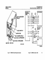
Jumper locations for 29M8 Control PWA __
Jumper locations for 29M8 Control PWA __
Jumper locations for 29M8 Control PWA _•
Jumper locations for 29M8 Actuator PWA.
Jumper locations for 29M8 VFO PWA ••••
Sample of Shugart and Xerox Error Maps.
Rigid Disk Drive or Proce$Sor Software
Preparation Flow Chart •••.••.•.• _•.•.
Actuator lock Installation .••••••.••••••
29MB Disk Drive Assembly .••••.•••••.•.
Read/Write PWA ..................... .
29MB Console Mechanical Parts ••••...••
Disk Drive Assembly .................. .
29MB Console Harnesses ••.•.••••.•••••
Control PWA (Version AI •••••••••••••••
Control PWA (Version BI •••••••••••••••
Actuator PWA ....................... ..
Test Connector ....................... .
29MB Disk Console Power Distribution •••
29MB Disk Console Plug/Jack Locations ••
29MB Power Cable W20 ............. ..
29MB Signal Cable W21 .............. .
Connector Type B .................... .
Connector Type D .................... .
3-4
]-4
]-5
]-5
figure
7·6
7·7
7·8
Page
Connector Type H
Connector Type R
Connector Type S
7·5
7·6
7·6
]-6
]·7
]·8
]·11
]·12
]·17
4·)
4·5
4·7
6-4
6-5
6-6
6-17
6-19
7·]
7·]
7·4
7·5
7-5
v
1. GENERAL DATA
29MB DISK CONSOLE
6OOP84228
CHAPTER 1 GENERAL DATA
29MB DISK CONSOLE SERVICE MANUAL
1-1
1. GENERAL DATA
HOW TO USE THIS MANUAL MODEL CONFIGURAnONS CALL MANAGEMENT CHANGE TAG INDEX
HOW TO USE THIS MANUAL
I
11.4
CHANGE TAG INDEX
29MB DISK CONSOLE
600PB42Z8
I
This service manual provides information necessary for maintenance of the 29MB Disk Console.
Refer to the BOOO Series Reference Manual for instructions about
use of matrix tags and Tag letter Classification definitions.
The 8000 Series Reference Manual provides the complete
instructIons for use of 8000 Series service manuals.
The 29MB Disk Console has one matrix tag. The matrix tag is
located on the bottom frame on the left side of the console. Any
important modification of the disk drive, or related cables and
connectors, must be indicated on the 29MB Disk Console matrix
tag.
11.2
MODELCONFIGURAnONS
I
Various models of 8000 Series products are available. The BOOO
Series Reference Manual provides product codes. model
configur.ations, and catalog number information, as well as
related explanations.
11.3
CALL MANAGEMENT
I
The Call Management procedures are to be performed during
every service call. The complete Call Management procedures are
provided in the 8000 Series Reference Manual.
1·2
1. GENERAL DATA
29MB DISK CONSOLE
600PB422B
CHANGE TAG INDEX
CHANGE TAG INDEX FOR 29MB DISK CONSOLE
Serial No.
Cut-in
Tag No.
Description
1
N
Tag 1 moves slide·lock hardware from 29MB Signal Cable to Processor connector panel to prevent
improper connection at Processor. Related part is the 29MB Signal Cable 152SB1277
2
CANCEllED
3
R
Tag 3 changes the molded connector hood on 29MB Signal Cable to eliminate interference between
cable connector and rear cover. Related part is the 29MB Signal Cable 1525825031.
T25131-
225
R
Tag 225 changes the molded connector hood on 29MB Signal Cable to eliminate interference
between cable connector and rear cover. Related part is the 29M8 Signal Cable 152S825031.
T25131-
T25-lnitial
1-4
2. INSTALLATION/REMOVAL
29MB DISK CONSOLE
600PB422B
CHAPTER 2 INSTALLATION/REMOVAL
29MB DISK CONSOLE SERVICE MANUAL
REFER TO 8000 SERIES REFERENCE MANUAL
2·'
3. REPAIR DATA
29MB DISK CONSOLE
iOOPB4ZZB
CHAPTER 3 REPAIR DATA
29MB DISK CONSOLE SERVICE MANUAL
3. REPAIR DATA
29MB DISK CONSOLE
600P8422B
CONSOLE TOP COVER CONSOLE FAN
1.1
CONSOLETOPCOVER
REF Pl4.1
REMOVAL
\.
SWITCH Off SYSTEM POWER.
2
REMOVE BOTH CONSOLE SIDE COVERS.
3
REMOVE CONSOLE TOP COVER.
a
b.
Remove the six speed nuts securing the Top Cover to
frame.
Remove Top Cover.
REPLACEMENT
1
REPLACE CONSOLE TOP COVER.
a.
3.2
Perform removal procedure in reverse order.
CONSOLE fAN
REF PL4.1
REMOVAL
1.
SWITCH Off SYSTEM POWER.
2
REMOVE CONSOLE REAR COVER.
3.
REMOVE THE CONSOLE FAN.
a.
b.
c.
d.
3-2
Remove screws securing the Fan Cover to frame.
Remove the Fan Cover.
Disconnect harness connector from the Fan.
Remove the Fan from console.
REPLACEMENT
CAUTION
The Fan must be installed with arrow pointing to rear of wnsole
for the correct air flow.
I.
REPLACE THE CONSOLE FAN.
a.
Perform removal procedure in reverse order.
3. REPAIR DATA
29MB DISK CONSOLE
600P8422B
3.3
29MB DISK DRIVE
3.
4.
5.
29MB DISK DRIVE
REF PL4.2
6.
REMOVAL
NOTE: RX only. References in the following procedures to a call
for assistance or report of conditions, should be made to the RX
Technical Specialist.
CAUTION
Drive replacement deletes customer files.
This requires
restoration of files by customer. BEFORE replacing drive, contact
RES or NSC; then notify customer's System Administrator or
Network Coordinator. Customer MUST be notified ~
replacing rigid drive. It is possible that Systems Analyst will
know work around procedure, and drive will not require replacing. If customer will not agree to drive replacement, contact
Systems Analyst for further instructions. NEVER REPLACE DISK
DRIVE WITHOUT FIRST NOTIFYING CUSTOMER AND SYSTEMS
ANALYST.
ENSURE THAT THE CORRECT DISK DRIVE REPLACEMENT
PROCEDURE IS FOLLOWED
a.
Ensure that RES or NSC is informed.
Customer has approved and understands that disk
b
drive is to be replaced
Systems Analyst has been informed.
c
SWITCH OFF SYSTEM POWER.
REMOVE BOTH SIDE COVERS.
INSTALL ACTUATOR LOCK (REPLACEMENT 3.3.1).
INSTALL SPINDLE LOCK (REPLACEMENT 3.3.2).
REMOVE 29MB DISK DRIVE
a.
Disconnect power harness connector from J4 on Disk
Drive Motor.
b.
Disconnect power harness connector from 13 on
Actuator PWA.
c.
Disconnect signal harness connector from 11 on the
Control PWA.
d.
Remove the four bolts securing the Disk Drive to
frame.
e. Carefully pull Disk Drive from console.
f.
Remove brackets from Disk Drive.
REPLACEMENT (FIGURES 3-1 TO 3-5, INCLUSIVE)
CAUTION
Jumpers on new Disk Drive must be configured to match old Disk
Drive jumper location BEFORE installation. Several Control PWAs
are now in use. Ensure that the correct figure is referred to when
verifying the jumper locations.
1
INSTALL JUMPERS ON DISK DRIVE PWAs.
a.
Refer to Figures 3-1 to 3-5, inclusive, and install
Jumpers as shown.
b
Remove any jumpers not shown in figures.
Add any jumpers necessary, as shown in figures.
3-3
3. REPAIR DATA
29MB DISK CONSOLE
6OOPB4228
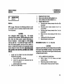
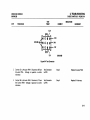
FIGURES 3-1, 3-2
-,
5
T
OS
§~
1111
R I
Y
-C
o -
TP2
T
oTP2
X
5C BC
-0
TP28 0
J1
0
TP1
-
S
L
TP2ti 0
0
TP4
0
TP3
§~
~llIllIlg IglI:
Shorting Plug
5RF
o
TP18
r
!L":TP=:1:---..I-
ISL TP1
o
TP14
o
o
0
TP22
Figure 3-1 Jumper Locations for 29MB Control PWA
(Version A)
0
m
_0000
R S F
SHORTING PLUG
TP210 oTPJ2 o
TP22
TP13
BC
8 1 ti 5 9 10 11
SC-~ o~-oo
1 2 34
TP1ti L 5 B TP2ti 0 _ 051
52
TP19
oTP11
o
o
TP20
TP13
TP21
o
TPl1
8010·049
3·4
~~
o
gig
TP12
o
0
TP23
J1
1- TERMINATORCHIPIN5TALLED
oTP11
0
TP28
_ST dTERMINATORCHIPINSTALLED
-DS1
- 0 51
S2
0
TP1
T
0
TP15
8010·050
Figure 3-2 Jumper Locations for 29MB Control PWA
(Version B)
3. REPAIR DATA
29MB DISK CONSOLE
&OOP84228
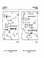
FIGURES 3·3, 3-4
o -
Tn T
_RV
0
TP28
m
&
0
TPU
JJ
_ST c:::::STERMINATOR CHIP INSTALLED
-DS1
~
§I
~~
IsL
o TP1
o
o
TP17
5
·5 -.0 ·15
1
m
_0000
R 5 F
o
TP:I
SHORTING PLUG
TP21
TP12
. °TP~2 0
9" J
8C
TP7
000
0
I T'::4
:==::::,..,f
I
:I
oo
8 7 & 5
9 10 11 12
SC-'y0~-oo-
12 J 4
TP1& L S B TP2& 0 _ oS1
0
TP5
0
TP15
0
52
TP19 0
o TP20
cs. SS
TP&
J8
TP7
0
8010-051
2
1
o
TP1
8010-052
Figure 3-3 Jumper Locations for 29MB Control PWA
(Version C)
Figure 3-4 Jumper Locations for 29MB Actuator PWA
3-5
3. REPAIR DATA
29MB DISK CONSOLE
fiO0P84228
29MB DISK DRIVE FIGURE 3·5
2.
o
TP10
o
CO
TPI
_0
o
TP4
o
TPB
0
TPll
o
0
TP3
3.
TP5
NOTE: The 29MB Disk Drives have bad page error maps from the
OEM supplier (the Original Equipment Manufacturer of the drove)
and Xerox. Refer to Figure 3·6 for a sample of the error map
Refer to Figure 3·7 for a flow chart on preparing the drive for
software.
o
TP7
oTpg
o
NOTE 1: 6R JUMPER PRESENT ONLY
ON lATER VERSIONS OF VFO PWA.
REPLACE 29MB DISK DRIVE.
a.
Replace brackets onto new Disk Drive.
b.
Carefullv install Disk Drive inside console.
c.
Replace the four bolts securing the Disk Drive to
frame.
d.
Remove spindle lock screw through the access hole
in Drive Belt Cover.
e.
Connect powe, harness connector to J4 on Disk Drive
Motor.
f.
Connect power harness connector to J3 on Actuator
PWA.
g.
Connect signal harness connector to J1 on the
Control PWA.
REMOVE ACTUATOR LOCK (3.3.1).
7
1
8
14
o
8010·053
Figure 3·5 Jumper locations for 29MB VFO PWA
4
CHECK THE AVAILABILITY OF XEROX ERROR MAP.
a
Remove map from the right side of drive
b.
locate date on the Xerox error map If dated 11·30·
B2 or before, or the map does not exist, proceed to
step 12
3. REPAIR DATA
29MB DISK CONSOLE
&OOPB422B
29MB DISK DRIVE fiGURE 3-&
5.
OEM ERROR MAP
SA 1004 SCAN ERROR LOG
SERIAL IA36497
TRK HD
BYTE COUNT LENGTH (BITS)
078 00
01315
14
144 03
02219
15
145 03
02220
03
253 03
03938
01
254 03
03939
02
RUN ALAG AND VERIFY A SUCCESSFUL COMPLETION.
a.
If ALAG completes successfully, proceed to step 6.
b.
If ALAG fails while PV Scavenger is running, proceed
to step 6.
c.
If ALAG does not complete and an MP Code other
than 1799 is displayed, see MP Code List.
d. If physical IJ{J/ame need. forward conuer.ion
Warning. is displayed on the screen, proceed to step
13.
.
CAUTION
END ERROR LOG
The follOWing steps contain instructions that will destroy
customer files. DO NOT logon with Analyst plivileges, or
perform these steps. unless service manual procedures Instruct
you to do so. Performing these e.ercises on Disk Drives
containing any customer files will DESTROY All CUSTOMER
INFORMATION.
XEROX ERROR MAP
XX Megabyte Storage DevICe
Serial number: A 12102
Dale; 22·Jan·82
Page
3908
14420
Cyl
017
064
HD
03
03
8adPage
Sec
Table
16
X
00
6.
Manual
Entry
Media
Scan
X
Number of bad pages: 2
7.
LOGON WITH ANALYST PRIVILEGES.
a.
Refer to 8000 NS Diagnostics Handbook for detailed
instructions.
RUN DISK EXERCISER FOR 10 PASSES TO DETERMINE THE
CONDITION OF THE HARDWARE.
a.
Refer to the 8000 NS Diagnostics Handbook on how
to run Disk hemser.
b.
If an error is· detected other than a Header CRC.
label CRC. Of Data CRC, perform Levell Checkout in
the 8000 Processor Service Manual.
8010·054(1)
Figure 3-& Sample of OEM and XerOJl
Error Maps
]·7
3. REPAIR DATA
19M8 DISK CONSOLE
&OOP84228
FIGUREl·7
NO
8adPages
,...----4.: Are Detected With
Destructive Scan
Bad Pages
Are Detected With
Media Scan
YES
i
YES
:~. Bad Pages On Xerox ;
;: Map and ones From
r----f::: Destructive Scan Are
'----.tlR~u~n~A~L~.A~GJI"--------r-::==~
t
~·B
Figure )-7 Rigid Disk Drive or Processor Software Preparation Flow Chart
.!
In Bad Page Table
8010-047(2)
3. REPAIR DATA
29MB DISK CONSOLE
600PB422B
29MB DISK DRIVE
c.
8
If no error is detected, or the error is a Header CRC,
Label CRC, or Data CRC, continue with step 8.
RUN DESTRUCTIVE SCAN fOR 2 PASSES, WITH 2 RETRIES.
a
Refer to 8000 NS Diagnostics Handbook for detailed
b.
c.
instructions.
b
CAUTION
When performing the next step, RESTORE the Bad Page Table.
9
10
11.
12
d.
If bad pages are detected while Destructive Scan is
running, record and save to use later.
fORMAT DISK DRIVE, RESTORING OLD BAD PAGE TABLE.
a.
Refer to 8000 NS Diagnostics Handbook for detailed
instructions.
VERifY BAD PAGE TABlE CONTAINS All PAGES ON
XEROX ERROR MAP AND PAGES RECORDED DURING
DESTRUCTIVE SCAN
a.
Compare Bad Page Table on the display to Xerox
error map, and pages recorded during Destructive
Scan.
b
If !!1! pages are in the Bad Page Table, proceed to
step 16.
MANUALLY ENTER BAD PAGES NOT IN BAD PAGE TABLE,
THEN PROCEED TO STEP 16.
a.
Refer to 8000 NS Diagnostics Handbook for detailed
instructions.
b.
After entering bad pages, proceed to Step 16.
RUN ALAGAND VERifY A SUCCESSfUL COMPLETION.
a.
If ALAG completes successfully, proceed to step 13.
If ALAG fails while PV Scavenger is running, continue
with step 13.
If ALAG does not complete and an MP Code other
than 1799 is displayed, see MP Code List.
If physical volume need. forward <OIiver,ioli
Waming. is displayed on the screen, proceed to step
13.
CAUTION
The following steps contain instructions that will destroy
customer files. QQ.J!QI logon with Analyst privileges, or
perform these steps, unless service manual procedures instruct
you to do so. Performing these exercises on Disk Drives
containing any customer files will DESTROY ALL CUSTOMER
INFORMATION.
NOTE: If you cannot logon (system locked up), perform an
Alternate Boot 0002, and press the BREAK or STOP key when
fault Analysis begins.
13.
14
LOGON ON WITH ANAI.YST PRIVILEGES.
a.
Refer to 8000 NS Diagnostics Handbook for detailed
instructions.
RUN NEW DISK CHECKOUT fOR 10 PASSES TO DETERMINE
THE CONDITION Of THE HARDWARE.
a.
Refer to the BOOO NS Diagnostics Handbook for
detailed instructions.
3·9
3. REPAIR DATA
29M8 DISK DRIVE
If an error is detected other than a Header CRC,
Label CRe, or Data CRC while Destructive Exerciser is
running. perform Level 1 Checkout in the 8000
Processor Service Manual
If no error is detected while Destructive Exerciser is
running, or the error is a Header CRC, Label CRC, or
Data CRC, continue with next step
d
When Do yvu wi." ,<> ,.,wl.,rucll". bad page lable al
Ihi.,ime (YIN): Y is displayed, press return.
e
When Do you wi.h 10 puto,m a media SL'an (YIN): is
displayed, type y and press return.
When Pa •• counl (/ ·1000) /0 is displayed, type 2
and press return.
g.
When Relr.y Cvalll (0·20): 2 is displayed, press return.
h.
If bad pages are detected while media scan is
running, record and save to use later.
If Du yuu wi.h 10 , •• , Ihe bad page. (YIN): is
displayed, type n and press return.
When Do you wi.h Iv manually .n/e, bad page.
(YIN): is displayed, type y and press return.
k.
If Xerox error map was dated 11·30·82 or before,
proceed to step 15.
Select Page Format and enter bad pages from Xerox
error map and bad pages detected during media
scan.
m
Proceed to step 16.
MANUALL Y ENTER BAD PAGES FROM OEM MAP AND
MEDIA SCAN.
a.
Refer to the 8000 NS Diagnostics Handbook for
detailed instructions.
b.
15
3·10
29MB DISK CONSOLE
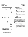
fiOOP8422B
ACTUATOR LOCK
16.
17.
18.
19.
3.3.1
RUN ALAG AND VERIFY A SUCCESSFUL COMPLETION.
RETURN ERROR MAPS TO PLASTIC POUCH.
REPLACE COVERS.
INFORM SYSTEM ADMINISTRATOR TO PARTITION DISK,
INSTALL SYSTEM SOfTWARE, AND RESTORE FILES.
ACTUATOR LOCK
REF PL 4.2
REMOVAL
NOTE: Some 29MB Disk Drives are not equipped with Actuator
Locks. Do not perform procedure if drive is without Actuator
Lock feature. (See PL 4.2 for Actuator Lock part number.)
1
2.
3
SWITCH OFF SYSTEM POWER
REMOVE LEFT SIDE COVER.
REMOVE ACTUATOR LOCK (FIGURE 3·8).
a.
Disconnect power harness connector from J3 on the
Actuator PWA.
b.
Switch ON system power.
CAUTION
Do not move Damper Assembly until disk speed has been
reached (approximately five seconds after AC power is applied).
Movement of heads without disk rotation may cause disk or
head damage.
C.
Wait for disk to reach proper speed.
3. REPAIR DATA
29MB DISK CONSOLE
IiOOPB422B
ACTUATOR LOCK
fiGURE 3-8
d.
4
Remove Actuator Lock from motor and damper
assembly by pulling it down.
e.
Place lock on shelf above Disk Drive.
f.
Switch OFF system power.
g.
Connect power harness connector to J3 on Actuator
PWA.
REPLACE LEFT SIDE COVER.
REPLACEMENT (Figure 3-8)
NOTE: Some 29MB Disk Drives are not equipped with Actuator
Locks Do nOl perform procedure if drive is without Actuator
Lock feature. (See PL 4.2 for Actuator Lock part number.)
1
2
3
SWITCH Off SYSTEM POWER
REMOVE BOTH SIDE COVERS.
INSTALL ACTUATOR LOCK (FIGURE 3-8).
a
Disconnect power harness connector from J3 on
Actuator PWA
b
Switch ON system power.
CAUTION
Do not meve Damper Assembly until disk speed has been
reached (approximately five seconds after AC power is applied).
Movement of heads without disk rotation may cause disk or
head damage.
c
d.
Wait for disk to reach proper speed.
Remove dampercover
Figure 3-8 Actuator Lock Installation
3-11
3. REPAIR DATA
ACTUATOR LOCK
SPINDLE LOCK
e.
4
3.3.2
29MB DISK CONSOLE
6OOP8422B
FIGURE 3·9
Rotate damper clockwise, and observe that actuator
arm moves on disk
t.
Wait for arm to stop.
g.
Install Actuator Lock between damper and star.
h.
Rotate damper clockwise until lock snaps into
position on damper collar.
Replace damper cover
j
Switch OFF system power.
k
Connect power harness connector to J3 on Actuator
PWA
REPLACE BOTH SIDE COVERS.
BELT COVER
SPINDLE LOCK
SPINDLE LOCK
REF PL 4.2
REMOVAL (FIGURE 3·9)
REMOVE LEFT SIDE COVER.
I
2
REMOVE SPINDLE LOCK
a
Remove spindle lock screw through the access hole
in drive Belt Cover.
b
Place lock in storage hole, indicated by the label at
bottom of frame.
REPLACE LEFT SIDE COVER.
o
0
ACTUATOR LOCK
CONTROLPWA
READIWRITE PWA
8010-056
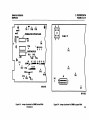
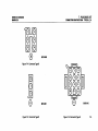
Figure 3-9 29MB Disk Drive Assembly
3-12
3. REPAIR DATA
29MB DISK CONSOLE
600PB422B
SPINDLE LOCK
CAUTION
DO NOT switch ON system power when spindle is locked.
SWITCH OFF SYSTEM POWER.
REMOVE LEfT SIDE COVER
REMOVE DRIVE BELT COVER.
CAUTION
DO NOT rotate spindle in a counterclockwise direction. Disk and
heads may be damaged.
S
6.
3.4
29MB DRIVE MOTOR
CAUTION
REPLACEMENT
4
29MB ORIVE BELT
INSTALL SPINDLE LOCK.
a.
Rotate spindle slowly In a clockwise direction onlv
until hole in pulley aligns with hole in casting.
b
Remove spindle lock screw from storage hole.
c. Insert spindle lock screw and tighten.
REPLACE DRIVE BELT COVER
REPLACE LEfT SIDE COVER.
29MB DRIVE BELT
REFPL4.2
REMOVAL
1
SWITCH OFF SYSTEM POWER
2
REMOVE LEFT SIDE COVER.
3
REMOVE DRIVE BElT COVER.
DO NOT rotate spindle in counterclockwise direction. Disk or
heads may be damaged.
4.
REMOVE DRIVE BELT
a.
Rotate spindle slowly in a clockwise direction only.
and work belt off pulley.
REPLACEMENT
NOTE: Ensure that Drive Belt is installed with part number on
outside.
1.
3.5
REPLACE DRIVE BELT
a.
Perform removal procedure in reverse order.
b.
RunALAG.
29MB DRIVE MOTOR
REF Pl42
REMOVAL (FIGURE 3·9)
1
SWITCH OFF SYSTEM POWER.
2.
REMOVE BOTH SIDE COVERS.
3.
INSTALL ACTUATOR lOCK
4.
DISCONNECT POWER HARNESS CONNECTOR FROM J4 ON
DRIVE MOTOR
5.
REMOVE DRIVE BEl T (3.4).
NOT!: Do not replace Drive Belt Cover.
6.
INSTALL SPINDLE LOCK (REPLACEMENT 3.3.2).
3. REPAIR DATA
29MB DISK CONSOLE
600P8422B
29MB DRIVE MOTOR
7.
8
REMOVE CAPACITOR fROM BRACKET.
a.
Place small screwdriver under top edge of capacitor
bracket.
b.
To remove capacitor. carefully apply pressure with
screwdriver, and pull on body of capacitor.
REMOVE DRIVE MOTOR.
a.
Remove Drive Motor connector J4 from bracket.
b
Remove the two screws securing the motor relay to
casting.
NOTE: Ensure that the insulating washers are on both sides of
motor mounts. and that motor does not touch casting.
2.
NOTE; Ensure that the insulating washers on both sides of
mOlOr mounts, are glued to casting or motor.
REPLACE DRIVE MOTOR.
a.
Ensure that there are insulating washers glued to
motor mounts or motor.
b.
Support the motor while threading the capacitor,
relay, and power connector J4 through hole in
casting.
c.
Install the four screws and four insulating washers,
but do not tighten.
CAUTION
9
Support the motor while removing the four
mounting screws.
d
Remove Drive Motor assembly from casting.
REMOVE PULLEY.
a
Loosen the two set screws on Drive Motor pulley.
b
Remove pulley from motor shaft.
Keep pulley for use with new Drive Motor.
REPLACEMENT
1
REPLACE PUllEY
a
Align one set screw with flat side of motor shaft, and
install pulley onto shaft.
b
Place 0.035 inch (0.88) shim between outer edges of
pulley and motor.
c.
Move pulley against shim, and tighten set screws.
d.
Remo.e shim.
3-14
Do not apply too much torque to screws, or the insulating
washers will split.
d.
e.
3.
4.
5.
6.
Attach ohm meter leads to casting and motor.
Tighten the four screws and observe meter to ensure
that motor does not touch casting.
f.
Remove meter leads Irom motor and casting.
g.
Position relay and replace the two screws securing it
to the casti ng
h.
Install capacitor Into bracket
Install Drive MOlor connector 14 into bracket.
i.
REMOVE SPINDLE LOCK SCREW AND PLACE IN STORAGE.
REPLACE DRIVE BElT (34).
CONNECl POWER HARNESS CONNECTOR TO DRIVE
MOTOR CONNECTOR 14.
REMOVE ACTUATOR LOCK (3.3.1).
3. REPAIR DATA
29MB DISK CONSOLE
6ooPB422B
7
8.
3.6
ACTUATORPWA
RUNALAG.
REPLACE BOTH SIDE COVERS
ACTUATORPWA
REf PL4.2
REMOVAL (fiGURE 3·9)
I
SWITCH Off SYSTEM POWER.
2
REMOVE LEfT SIDE COVER.
3
REMOVE DRIVE BELT COVER.
CAUTION
Do nol cause any disk movement by moving the drive belt.
4
REMOVE ACTUATOR PWA
a.
Remove JB connector from Actuator PWA
b.
Remove power harness connector from Actuator
PWAJ3.
(
Remove the four screws securing PWA to casting.
d.
Move PWA slightly to left and disconnect pg and Pl0
fromPWA.
e.
Remove Actuator PWA.
REPLACEMENT (fiGURE 3·4)
1
INSTALLJUMPER ON ACTUATOR PWA.
a.
ReIer 10 figure 3·4 and install jumper as shown.
REPLACE ACTUATOR PWA.
2
Perform removal procedure in reverse order.
a
3.
SWITCH ON SYSTEM POWER.
4
RUNALAG.
3.1
VfOPWA
CONTROLPWA
VfOPWA
REF PL4.2
REMOVAL (fiGURE 3·9)
1.
SWITCH Off SYSTEM POWER.
2.
REMOVE LEFT SIDE COVER.
3.
REMOVE VfO PWA.
a.
Release clips securing corners 01 PWA. and remove
from mounting studs.
b.
Disconnect P2 and P3 connectors from VfO PWA.
REPLACEMENT (fiGURE 3·S)
1.
INSTALL JUMPERS ON VfO PWA.
a.
Refer 10 Figure )·5 and install jumpers as shown.
2.
3.
4.
3.B
REPLACE VfO PWA
a.
Perform removal procedure in reverse order.
SWITCH ON SYSTEM POWER.
RUNALAG.
CONTROL PWA
Ref PL4.2
REMOVAL (fiGURE 3·9)
1.
REMOVE VfO PWA (3.7).
2.
REMOVE CONTROL PWA.
a.
Remove signal harness connector from 11 on Control
PWA
b.
Disconnect harness from J7 on Control PWA.
3·15
29MB DISK CONSOLE
6001'84:128
3. REPAIR DATA
CONTROL PWA
c.
d.
e.
READIWRITE PWA
a.
Remove the four screws securing the PWA to casting.
Move f'WA to left, and disconnect from ReadlWrite
PWA.
If Control f'WA is being replaced, remove the two
ribbon cables from f'WA.
b.
Remove the two screws on left side of ReadlWrite
f'WA.
Remove the six screws from center of ReadlWrite
f'WA.
CAUTION
REPLACEMENT (FIGURES 3-1,3-2,3-3)
Do not pull held cables through sell. This will reduce slick
Inside the Disk Drive Ind prevent ,ums from moving properl~.
CAUTION
Jumpers on new Control PWA must be configured to match old
Control PWA jumper locations BEfORE installation. Several
Control PWAs are now in use. Ensure that the correct figure is
referred to when verlf~ing the jumper locations.
c.
1.
Refer to Figures 3-1,3-2, and 3-3 and install jumpers
as shown.
b.
Remove any jumpers not shown in figures.
c.
Add any jumpers nece.sary, as shown in figures.
REPLACE CONTROL PWA
a.
Perform removal procedure in reverse order.
SWITCH ON SYSTEM POWER
RUNALAG.
a.
2
3
4
3.9
READIWRITE PWA
REF PL4.2
REMOVAL (FIGURE 3-9)
1.
REMOVE CONTROL PWA (3.8).
2
REMOVE DAMPER ASSEMBLY COVER.
3.
REMOVE READIWRITE PWA.
3-16
Carefull~
pull ReadlWrite PWA away from casting
enough to reach behind PWA Ind disconnect cables.
Disconnect cables from component side of
ReadlWrite PWA.
If rubber gasket adheres to ReadlWrite PWA, remove and
replace around hole in casting.
d.
REPLACEMENT (FIGURE 3·10)
NOTE: Cables are sequentially marked. P20 is at bottom, and
P28 is attop.
1.
REPLACE READIWRITE PWA.
a.
Ensure that rubber gasket is properly attached
around hole in casting.
b.
Carefull~ connect head cables on new PWA (figure
3·10)
c.
Push PWA against casting, ensuring that the wires
are not caught between f'WA and casting.
e.
Replace the eight screws securing the ReadlWrite
PWA to casting.
3. REPAIR DATA
29MB DISK CONSOLE
600PB422B
CONTROL PWA
2.
3.
4.
5.
COMPONENT SIDE
6.
J2B1P2B
3.10
6lQ:oooool1
J23/P23
6100 00 0Q]
1
P6
J22/P22
610000001
fiGURE 3·10
REPLACE CONTROL PWA (38)
REPLACE VFO PWA (3 7)
SWITCH ON SYSTEM POWER
RUN AlAG.
REPLACE LEFT SIDE COVER
DAMPER ASSEMBLY
REF Pl4.2
REMOVAL
1.
SWITCH Off SYSTEM POWER.
2.
REMOVE BOTH SIDE COVERS.
3.
REMOVE DAMPER ASSEMBLY
a.
Disconnect power harness
Actuator PWA.
b
Switch ON system power.
connector
J3
from
CAUTION
1
DO NOT mowe Damper Assembly until disk speed has been
reached (approximately fiwe seconds after AC power is applied).
Movement of the heads without disk rotation may cause disk or
head damage.
c
d.
J20/P20
610000001
DAMPER ASSEMBLY
1
J211P21
610000001
READIWRITE PWA
1
e
B010·057
f.
Remove damper cower
Rotate damper counterclockwise until actuator arm
is located against the outer stop.
loosen set screw securing the damper and collar to
actuator motor shaft.
Remove damper assembly from shaft.
Figure 3·10 ReadIWrite PWA
3·17
3. REPAIR DATA
21M8 I)tSK CONSOLE
600P84ZZ8
DAMPER ASSEM8L Y
REPLACEMENT
CAUTION
AC power must be applied while installing Damper Assembly.
1.
REPLACE DAMPER ASSEMBLY.
a.
Ensure that harness connec:tor J3 is disconnected.
b
Switch ON s~stem power.
Install Damper Assembl~ onto actuator motor shaft.
NOTE: Ensure that damper and collar are NOT in contact with
actuator motor housing.
d.
Tighten set screw secunng the damper to actuator
motor shaft.
Replace dampercover.
f.
Switch Off system power
g.
Connect power helrness connector to J3 on Actuator
PWA.
SWITCH ON SYSTEM POWER.
RUNALAG.
REPLACE BOTH SIDE COVERS
e.
2
3
4.
3-18
4. PARTS IDENTIFICATION
29MB DISK CONSOLE
600PB422B
CHAPTER 4 PARTS IDENTIFICATION
29MB DISK CONSOLE SERVICE MANUAL
USO/XCONLY
4-1
4. PARTS IDENTIFICATION
USO/XCONlY
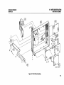
29MB CONSOLE MECHANICAL PARTS
IPL 4.1
ITEM
I
2
3
4
5
6
7
8
9
10
11
12
13
14
15
16
17
18
19
4-2
29MB CONSOLE MECHANICAL PARTS
I
PART NO.
DESCRIPTION
2P81938
NSC: 2P820 11
127P1275
2581969
NSC:30P83957
2581967
26P80475
17P80207
3P1454
17P80199
2581968
NSC: 91P81325
601S920
Cover, Top
Plate, fan Cover
fan, Console
Cover, Rear (includes item 13)
Bracket, Drive Mounting
Cover, Side (includes item 13)
Stud, Castor Locking
Castor, Rear
Clip, Quarter Turn Receptacle
Castor, front
Cover, front (includes 12, 13)
label,logo
Kit, Quarter Turn Hardware
Stud, Quarter Turn (P/O item 13)
Spring, Ejector (P/O Item 13)
Washer, Nylon (P/O item 13)
Retainer, Split Ring (P/O Item 13)
8ezel, front Cover
Nut, Speed
N5C:2P82021
NSC:29P80410
29MB DISK CONSOLE
6OOP84228
A
B
C
D
E
f
NSC:
D
112W39710
112W75810
20lW21802
256W11402
Sems Screw (8-32.7/16)
Sems Screw (1/4-20. 1/2)
Nut (114-20)
Washer (1/4)
Screw (RX only)
Screw (RX only)
Call the Network Support Center to obtain parts.
Removal and Replacement 3.1, 3.2
4. PARTS IDENTIFICATION
29MB DISK CONSOLE
600PB422B
29MB CONSOLE MECHANICAL PARTS
IS{INCLUOES
\.14 TO 17
:ij5
14
II
8000-007121
Figure 4-1 29MB Console Mechanical Parts
4-)
4. PARTS IDENTIfiCATION
USO/XCONLY
DISK DRIVE ASSEMBLEY
IPL 4.2
ITEM
1
2
3
4
5
6
7
8
9
10
11
12
13
14
15
DISK DRIVE ASSEMBLY
I
PART NO.
DESCRIPTION
99P80929
82P80897
99P80921
99P81093
99P87543
99P81095
99P87509
99P87511
99P81 094
Motor. 60Hz Drive
Drive Assembly, 29MB Disk
PWA, Actuator
Harness, C-A
Lock, Actuator (Note 1)
Damper Assembly
PWA, ReadlWrite
PWA,VFO
Harness, C-V
Terminator (RX only)
PWA, Control
Cover,8elt
Bel t, 60Hz Dri ve
Pulley, Belt
Kit, Belt Retainer
99P87510
NSC: 99P80924
99P80925
NSC: 99P80927
99P81226
A
B
C
o
E
f
G
H
J
NSC:
201W21802
256W11402
256W I 0902
It3W23002
112W39610
113W22402
113WI7208
259Wl0502
I 13W16602
Hex Nut (114-20)
Lockwasher (114)
Lockwasher (No.8)
Screw (8-32 x 5/8)
Screw (8·32 x 3/8)
Screw (8·32 x 114)
Spindle Lock Screw (4·40 x 3/4)
Spindle lock lock washer (No.4)
Screw (4·40 x 3/8)
Call the Network Support Center to obtain parts.
NOTE 1: Actuator lock may not be provided on all disk drives.
D
4·4
29MB DISK CONSOLE
6OOP1422B
Removal and Replacement 3.1 to 3. 10, inclusive.
4. PARTS IDENTIFICATION
29MB DISK CONSOLE
600P84228
DISK DRIVE ASSEMBLY
8000-008(2)
figure 4·2 Disk Drive Assembly
4·5
4. PARTS IDENTifiCATION
USO/XCONLY
29Ma CONSOLE HARNESSES
IPLU 29MaCONSOLEHARNESSES
ITEM
2
3
4
5
6
7
6OOP8422B
I
PART NO.
DESCRIPTION
152525031
152525030
N5C: 19P20514
NSC: 19P20515
Cable W:U. 29MB Signal (TAGS 3, 225)
Cable W2t. 11MB Signal (alt.)
Clamp. Cable
Clamp. Cable
Block. Cable Tie (PIO item 1)
Cable W20. 29MB Power
Cover. Rear Cable (RX only)
Clamp. Cable (RX only)
152525440
29MB DISK CONSOLE
A
B
C
o
NSC:
112W36710
2SBW 10902
Screw (B-32 x 7/16)
Lockwasher (No. B)
Screw (RX only)
Screw (RX only)
Call the Network Support Center to obtain parts.
4. PARTS IDENTIFICATION
29MB DISK CONSOLE
&OOI'B422B
29MB CONSOLE HARNESSES
1000-00814'
Figure 4-) 29MB Console Harnesses
4-7
5. DISPLAY QUALITY
29MB DISK CONSOLE
6OOPB422B
CHAPTER 5 PRINT/DISPLAY QUALITY
29MB DISK CONSOLE SERVICE MANUAL
REfER TO APPROPRIATE SERVICE MANUAL
5·'
6. TROUBLESHOOTING
29MB DISK CONSOLE
600PB422B
CHAPTER 6 TROUBLESHOOTING
29MB DISK CONSOLE SERVICE MANUAL
6·1
6. TROUBLESHOOTING
INTRODUCTION
I
INTRODUCTION
I
Service Strategy
The ~tep~ required for isolation of faults in the 8000 Network
Sy~tem, are provided in the sequence below. These steps are
de~cribed in detail in the 8000 Processor Service Manual.
Instructions for using diagno~tic~ are provided in the 8000
Network Systems Diagnostics Handbook.
Perform Level 01 Trouble~hooting, using the Level 01
Trouble~hooting Flowchart.
2. Perform the Levell Checkout procedure.
3. Perform any Level 2 Check Chart procedures indicated by
Levell Checkout.
4. usa only. If necessary, ask for as~istance from the Region
Engineering Specialist (RES) or the Network Support
Center (NSC).
5. RX only. If neces~ary, a~k for assistance from the Technical
Specialist
Information obtained during fault i~olation (in the 8000 Proces~or
Service Manual) may refer you to this manual or other manual~.
U~e the appropriate amount of time (determined by the local
Then, if a
8ranch Manager) to troubleshoot a problem.
correction cannot be made, a~k for assi~tance.
'·2
29MB DISK CONSOLE
6OOPII4228
6. TROUBLESHOOTING
29MB DISK CONSOLE
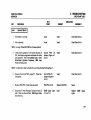
CHECK CHART 6.01
&OOI'B422B
STEP
PROCEDURE
16.01
29MB DISK FAULTS
1.
TEST
POINT
·5.2V
INCORRECT
I
Lower the VFO PWA. The following voltilge5, at
the Control PWA. are within tolerance:
a. 5.2V
b.
INDICAnON
CORRECT
Control PWA J6
(Figure 6-1)
PinJ
PinE
Step lb
Step Ie
Step 2
Step 2
CAUTION
When checking the 24V at Pin 22, switch OFF pow.r, .nd connect E·Z hook meter lead to Pin 221••d on the Control PWA (Figure 6-1).
Switch ON power.
c.
24V
d.
12V
Pin 22
PinB
Step ld
Check Chart 6.02
Step 2
Step 2
VOLTAGE TOlEIANCES
!!!!!!HI
I""K_THO
Pipit,. Me••r
uv
4.I105.i
.... '0·5.•
s,oz toUt
-s,oz to·U8
-S.ZV
·UV
UV
Z4V
·tt.O to·n.o
tt.O '011.0
22.0 .oZ6.0
·11.410·12.1
tt.4 IOU.'
n.' tozs.z
6. TROUBLESHOOTING
29MI DISK CONSOLE
600P84221
FIGUREti-1
02
4 DS
0
6
0
11'
S
T
S
L
1111
oTP2
R I
V X
-
0
TP1
-0
DE
T
0
TP4
0
TP3
A
0
TP5
5C IC
TP210 _ 0
051
TP260 0
52
TP7
J1
-C
0
TPI
0
Tpg
I~TERMINATOR CHIP INSTALLED
046
041
50
0
I
~lIllIlIg
SHORTING PLUG
SRF I
oTP11
TP17
0
0
TP11
0
TP10
1811';'I
818
TP19
o 0
TP20
PIN 22
DL1
TP21
o 0
TP22
TP12
0 0
TP13
TP15
o 0
TP16
TP14
0
0
TP27
0
TP2)
Figure 6-1 Control PWA (Version A)
6-4
0
TP6
TP25
0
0
TP24
I
C
C D
1
2
o~
E
T
P H
OJ
N K
E L
N M
T N
P
s R
I S
oT
E U
V
E
W
X
V
Z
21
22
8010-014
6. TROUBLESHOOTING
29M8 DISK CONSOLE
600P84228
FIGURE 6·2
-
0
IX
02
4
0
6
0
-RY
-ST
-OSl
J1
TP2
§~
¥'
I
I
T
GR
0
0
TP28
TP2)
DE
TP14
I'
oTPl
IsL
TP7
0
0
0
OK
N L
TERMINATOR CHIP INSTALLED
0
_0
0
0
TPS
_0000
TP17 TP16/ 12) 4
LSBTP26 0 _ oSl
52
TP19
oTPll
0
0
TP20
Tpg
0
TP27
R S F
SHORTING PLUG
TP21
TP12
o 0 0 0
TP22
TPU
8C
B 7 6 5 9 10 11 12
SC-o 0 0 _ - 0 0 _
PIN 22
0
TP15
0
0
TP18
TPti
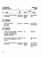
Figure 6-2 Control PWA (Version B)
1
2
P J
0
TP4
C.
046
048
50
0
TP8
A
B
C
D
C E
OF
MH
0
TP)
E
T
C
H
E M
N N
T P
R
S S
I T
oU
E V
W
X
Y 21
Z 22
E
0
S
I
0
E
8010-015
6-5
6. TROUBLESHOOTING
29MB DISK CONSOLE
600P8422B
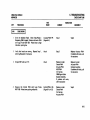
FIGURE '·3
o
TP2
TP40
o
TP1
o
JI
1
201 .......... 2
191-.··.... 1
J9
o
TP5
TP3
o
TN
o
TP1
Figure '·3 Actuator PWA
,.,
1010·016
6. TROUBLESHOOTING
29MB DISK CONSOLE
600P84228
PROCEDURE
STEP
2
CHECK CHART 6.01
TEST
POINT
D,sconnect C-A (ribbon) Harness connector JB
from Actuator PWA. All of the following voltages
are within tolerance:
Actuator PWA J8
(Figure 6-3)
a.
b
c
d
e
Pin8
Pin 10
Pin 12
Pin 14
Pin 16
Pin 19
Pin 20
Pin 18
f.
9
h
S.2V
S.2V
S.2V
S.2V
-S.2V
24V
24V
12V
All of the following voltages are within tolerance:
Actuator PWA J3
(Figure 6-3)
a
b
Pin 5
Pin4
Pin 1
S.2V
-S.2V
24V
INDICATION
INCORRECT
CORRECT
Replace C-A Harness.
If problem still exists.
replace Control PWA.
Step 3
Replace Actuator PWA
Replace
Cable
29MB
Power
VOLTAGE TOLERANCES
~
Xerox 6ooT860
D!Git~1
5.2V
-5.2V
•.8105.6
-4.810-5.6
·11.010-13.0
11.0 10 13.0
22.01026.0
5.02105.)8
-5.02 10 -5.)8
-IU 10·U.6
11 .• loU.6
22.81025.2
-I2V
I2V
2.V
Meter
6-7
6. TROUBLESHOOTING
29MB DISK CONSOLE
6OOP84228
CHECK CHARTS 6.02
STEP
PROCEDURE
16.02
DISK MP fAULT CODE
TEST
POINT
INDICAnON
CORRECT
INCORRECT
I
CAUTION
Performing the following steps with P43 connected.to the HSiO PWA will write over. and therefore destro~. customer files.
NOTE: When P43 is disconnected from the HSIO PWA, the system cannot determine if there is a 29MB, 42MB, or 10MB Disk Drive
installed. Since the 10MB Data Wrap Around test does not require the Disk Drive to be connected this is the test you should select.
2.
Disconnect P43 2!l!lt from HSIO PWA. Run ALAG.
Upon the completion of Test 0316, press STOP key
on BOlO Workstation or BREAK key on Server
Terminal. When the MP reaches 0399, type a d.
When MP reaches 0799, type an s then 31, then
press return. Test ran successfully IMP = 0799).
Visual
Connect P43 to HSIO PWA. Locate the original MP
Code from the list below, and access the specified
Check Chart.
Visual
a.
b.
c.
d.
e.
f.
g.
'·8
1611 to 1618, inclusive
1631 to 1636, inclusive
1641 to 1643, inclusive
1671 or 1672
1713
1741,1742, or 1791
None of the above
Step 2
Check Chart 6.02. 1
Check Chart 6.04
Check Chart 6.05
Check Chart 6.03
Check Chart 6.06
Check Chart 6.07
See MP Code List in Processor Service Manual
Replace HSIO PWA
6. TROUBLESHOOTING
29MB DISK CONSOLE
6DOP8422B
STEP
PROCEDURE
16.02.1
DISK NOT READY
CHECK CHART 6.02.1
TEST
POINT
INDICATION
CORRECT
INCORRECT
I
D(lve Motor is running.
Visual
Step 2
Check Chart 6.02.2
DISk is spinning.
Visual
Step 3
Check Chart 6.02.4
Control PWA DS
Jumper (Figure 6-1
or 6-2)
Step 4
Check Chart 6.02.3
NOTE: Use Logic Probe 600T1S80 for all measurements.
Verify that DS jumper is in the correct location at
DS I, then logon using xerox and cinos for name
and password. Enter the Isolation Tools. Select
Drive Select· Dynamic - frequency: 1000. Logic
Probe indicates pulses.
NOTE: Test selected in Step 3 should still be running while performing Step 4.
4
6.
Measure the Control PWA jumper RY. Probe indicates pulses.
Control PWA RY
Jumper (Figure 6-1
or 6-2)
StepS
Check Chart 6.02 S
Measure HSIO PWA. Probe indicates pulses.
HSIO PWA J43-22
Replace HSIO PWA
Step 6
DISconnect PI from Processor Connector Panel J2
and J1 from the Control PWA. 29MB Signal Cable
has continuity.
29MB Signal Cable
JI-FtoPI-12
Step 7
Replace
Cable
29MB
Signal
6·9
6. TROUBLESHOOTING
29MB DISK CONSOLE
6OOP8422B
CHECK CHARTS 6.02.1, 6.02.2, 6.02.3
STEP
7
Disconnect J43 from HSIO PWA. 29MB Interface
Harness has continuity.
NO MOTOR DRIVE
1.
NO DRIVE SELECT
INDICATION
CORRECT
INCORRECT
29MB Interface Har·
ness J2-12 to J43-22
Replace in order:
Control PWA
HSIOPWA
Replace 29MB Interface
Harness
Drive Motor J4-1 to
Replace Drive Motor
Check the 29MB Power
Cable; replace bad cable
I
Voltage at Drive Motor is as follows:
USO. 10llo 127VAC
~. 193 to 264 VAC
16 .02 .3
6-10
TEST
POINT
PROCEDURE
3
I
Press STOP on BOlO Workstation or BREAK on
Server Terminal. Select Drive Seled - Dynamic Frequency 1000. Measure HSIO PWA with Logic
Probe 600T1580. Probe indicates pulses.
HSIOPWAJ43-26
Step 2
Replace HSIO PWA
Disconnect PI from Processor Connector Panel J2
and J1 from the Control PWA. 29MB Signal Cable
has continuity.
29MB Signal Cable
J1-JtoPI-16
Step 3
Replace
Cable
Disconnect J43 from HSIO PWA. 29MB Interface
Harness has continuity.
29MB Interface Harness J2-16 to J43-26
Replace in order:
Control PWA
HSIOPWA
Check 29MB Interface
Harness connector for
loose pins; replace bad
harness
29MB
Signal
6. TROUBLESHOOTING
29MB DISK CONSOLE
600PB422B
STEP
CHECK CHARTS 6.02.4. 6.02.5
TEST
POINT
PROCEDURE
MECHANICAL ISOLA TlON
INDICATION
CORRECT
INCORRECT
I
Verify that Spindle Lock Screw and Actuator Lock
Visual
Step 2
Remove Lock Screw and
Actuator Lock (Procedures 3.3.\ and 3.32)
Verify that pulley iscorrectly installed.
Visual
Step3
Tighten or replace pulley
Verify that Drive Belt is correctly installed.
Visual
Replace in order:
Control PWA
HSIOPWA
Install Drive Belt
are removed
16.02 .5
LOGIC NOT READY
I
NOTE: Lower the VFO PWA to access the Control PWA. Place two sheets of paper under VFO PWA to prevent an electrical short from
PWA to disk console frame
I.
Measure the Control PWA with logic Probe
600T1580. Probe shows a high indication.
Control PWA TP 8
(Figure 6-\ or 6-2)
Replace in order:
R/WPWA
Control PWA
If problem still exists.
call for assistance.
Replace Control PWA
6-11
6. TROUBLESHOOTING
29MB DISK CONSOLE
600PB4228.
CHECK CHARTS 6.0), 60.).1
STEP
PROCEDURE
16.0)
LOGIC FAULT
TEST
POINT
6-12
INCORRECT
I
Measure the Control PWA with Logic Probe
600T1580. Probe shows a high indication.
16 .0 ).1
INDICATION
CORRECT
Control PWA TP 21
(Figure 6-1 or 6-2)
Check Chart 6.03. 1
Replace in order:
R/WPWA
Control PWA
If problem still exists, call
for assistance.
Run Fault Analysis. After an MP Code is displayed,
LogiC Probe 600l 1580 shows a low indication.
Control PWA TP 22
(figure 6-1 or 6-2)
Step2
Replace in order:
R/WPWA
Control PWA
If problem still exists, call
for assistance.
Measure the Control PWA with Logic Probe,
600T1580. Probe shows a high indication
Control PWA TP 12
(figure 6-1 or 6-2)
Step 3
Check Chart 6.02.1
Measure the Control PWA with Logic Probe,
600T1580. Probe shows a low indication.
Control PWA TP 13
(figure 6-1 or 6-2)
Step 4
Replace in order:
R/WPWA
Control PWA
If problem still exists, call
for assistance.
CONTROL FAULT
I
6. TROUBLESHOOTING
29MB DISK CONSOLE
6DDP84228
STEP
4.
6
16.04
CHECK CHARTS 6.03.1,6.04
TEST
POINT
PROCEDURE
INDICATION
CORRECT
INCORRECT
Measure the Control PWA with Logic Probe
600T1580. Probe shows a low Indication.
Control PWA Jl·30
(Figure 6·1 or 6·2)
Replace HSIO PWA
StepS
Disconnect PI from Proce.sor Connector Panel J2
and Jl from the Control PWA. 29MB Signal Cable
has continUity.
29MB Signal Cable
Pl·34 to Il·U
Step 6
Replace
Cable
Disconnect J43 from HSIO PWA.
Harness has continuity
29MB Interface Har·
ness J2·34 to J43·44
Replace Control PWA
Check 29MB Interface
Harness connector for
loose pins; replace bad
harness
Control PWA SC
Jumper (Figure 6·1
or 6·2)
Step 2
Replace in order;
Actuator PWA
C·A Harness
ControlPWA
HSIOPWA
Step 3
Replace Actuator PWA
TRACK SEEK INCOMPLETE
29MB Interface
29MB
Signal
I
Enter the Isolation Tools Select Step Pulses •
Frequency 1000 • Inward. Measure SC Jumper on
the Control PWA with Logic Probe 600T1580.
Probe shows pulsing indication.
NOTE; Test selected in Step 1 should still be running while performing Step 2.
Measure C Jumper on the Control PWA with Logic
Probe 600T1580. Probe shows pulsing indication.
Control PWA C
Jumper (Figure 6·1
or 6·2)
6·13
6. TROUBLESHOOTING
29MB DISK CONSOLE
600P8412B
CHECK CHARTS 6.04. 6.05
STEP
TEST
POINT
PROCEDURE
INOICATION
CORRECT
INCORRECT
NOTE: Test selected in Step 1 should still be running while performing Step 3.
Measure HSIO PWA with Logic Probe 600T1580.
Probe shows pulsing indication
16.05
HSIO PWA J43·8
Replace HSIO PWA
Replace
Cable
Enter the Isolation Tools Select Step Pulses •
1000 • Outward
When test stops.
logic Probe 600T1580 shows a high indication
(heads at track 00).
Actuator PWA J1()'1
(figure 6·3)
Step 2
Check Chart 6.6
Measure Actuator PWA with Logic
600T 1580 Probe shows a high indication.
Actuator PWA TP3
(Figure 6·3)
Replace in order:
ControlPWA
Actuator PWA
HSIOPWA
If problem still exists,
call for assistance.
Replace Actuator PWA.
If problem still exists, call
for assistance.
RESTOREERRORS
Signal
I
Frequenc~
6·14
29M8
Probe
6. TROUBLESHOOTING
29MB DISK CONSOLE
600P84228
STEP
PROCEDURE
16.06
SEEK ERRORS
4
CHECK CHART 6.06
TEST
POINT
INDICATION
CORRECT
INCORRECT
I
Enter the Isolation Tools. Select Step Pulses •
Frequency 1000· Inward. Measure Actuator PWA
with logic Probe 600T1580 Probe shows a high
indication, pulsing low.
Actuator PWA TPS
(figure 6·3)
Step 2
Step 4
Verify that heads are moving. (Repeat Step I,
selecting Outward, if necessary.)
Visual
Step 3
Replace Actuator PWA.
If problem still exists, call
for assistance.
Original MP code was 1713.
Visual
Replace in order;
ControlPWA
Actuator PWA
HSIOPWA
C·A Harness
29MB Signal Cable
Damper Assembly
If problem still exists,
call for assistance.
Replace in order;
Actuator PWA
Damper Assembly
If problem still exists, call
for assistance.
Measure the Control PWA with logic Probe
600T1580. Probe shows pulsing indication.
Control PWA )1·26
(figure 6·1 or 6·2)
Replace in order:
ControlPWA
C·A Harness
Actuator PWA
StepS
6·15
6. TROUBLESHOOTING
29MB DISK CONSOLE
600PB4228
CHECK CHARTS 6.06, 6.07, 6.08, 6.09
STEP
TEST
POINT
PROCEDURE
Measure HSIO PWA with Logic Probe 600Tl580.
Probe shows pulsing indication.
16.07
WRITEERRORS
COOLING FAN
RIGID DISC DRIVE LOADING
Replace
Cable
Signal
Replace in order:
HSIO PWA
29MB Signal Cable
Control PWA TP17
(figure 6-1 or 6-2)
Replace in order:
RlWPWA
VfOPWA
HSIOPWA
Replace in order:
ControlPWA
HSIOPWA
29MB Signal Cable
fan Connector P2-1
t02
Replace fan
Replace
Cable
29MB
Power
Test Connector
to RTN
Step 2
Replace
Cable.
29MB
Power
I
Connect J1 to rear of Processor and disconnect 13
from Actuator PWA. Voltage in questIon is within
tolerance.
6-16
HSIO PWA J43-36
(Harnessconnected)
I
Voltage at fan is as follows:
USO. 10310 127 VAC
~ 193t0264VAC
16.09
29MB
INCORRECT
I
Run fault Analysis. When 1740 is on the MP,
measure Write Data Pattern on Control PWA with
Logic Probe 600Tl580. Probe shows data flow
(High lamp lit steady, and Low lamp pulsates).
16.08
INDICATION
CORRECT
6. TROUBLESHOOTING
29MB DISK CONSOLE
600P8422B
STEP
CHECK CHART 6.09
TEST
POINT
PROCEDURE
FIGURE 6-4
INDICATION
CORRECT
INCORRECT
S.2V
-S.2V
RETURN
24V
-12V
12V
8010-009
Figure 6-4 Test Connedor
2.
Connect)3 to Actuator PWA. Disconnect)8 from
Actuator PWA. Voltage in question is within
tolerance.
Test Connector
to RTN
Step 3
Replace Actuator PWA
3.
Connect )8 to Actuator PWA. Disconnect)7 from
the Control PWA. Voltage in question is within
tolerance.
Test Connector
to RTN
Step 4
Replace C-A Harness
6-17
6. TROUBLESHOOTING
29MB DISK CONSOLE
600PB4228
CHECK CHAR".09
STEP
TEST
POINT
PROCEDURE
INDICAnON
CORRECT
INCORRECT
4.
Connect J7 to the Control PWA. Disconnect right
hand C·V (ribbon) Harness from bottom of the
Control PWA and 16 from the Control PWA.
Voltage in question is within tolerance.
Test Connector
to RTN
StepS
Replace Control PWA
S
Connect C·V (ribbon) Harness to the Control PWA.
Disconnect 12 from VFO PWA. Voltage in question
is within tolerance.
Test Connector
to RTN
Step 6
Replace C-V Harness
6
Connect 12 to VFO PWA. Voltage in question is
within tolerance.
Test Connector
to RTN
Step 7
Replace VFO PWA
Connect 16 to the (ontrol PWA. Voltage in ques·
tion is withon tolerance.
Test Connector
to RTN
Return to Level 1
Replace RJW PWA
l!OLTAGf TOLERANCES
VOltage
Xerox 6ooT86O
Digital Meter
5.2V
·S·2V
·UV
UV
24V
4.8 IOU
·4.810-5.6
-1I.01o·n.O
1t.0 10U.0
22.01026.0
5.02 105.)'
6·18
·5.0210-5.)8
-11.4 10 -\2.6
1t.4 10 12.6
22.8 1025.2
6. TROUBLESHOOTING
29MB DISK CONSOLE
600P84228
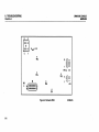
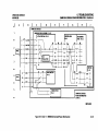
29MB DISK CONSOLE POWER DlSTRIBUnON FIGURE 6-5
B
A
D
C
I
liMB DISK ORIVI ASSIMBLY . PL 4.2
1
2
2
~
-!...
I
·1
-5.2 ATN
~(-!->+--,- ]
24VRTN
.2
t
~
,
_lpROC]
6
4
5VRTN
:
5
i
I
I
4 - : - -5.2V
1 -.;.... 24V
3
ACTUATORPWA·PU.2
E:1
y
J8
/T
~ >-4---<l~~-"':
»-------~:
I
7.'
I1.U
1.
Ii
I
I
:
5.2V
\[1
JJ
I
I
I
F
E
21MB OISII CONSOLE
1'.20
.,10
I
CONTROLPWA
PL4.a
4---!7I
I
++
--T--:~
I
I
H
G
F.K
7.'
I1.U
16
1.
RIAO/WRITf
'WA·PL4.2
-i-"H~-+-
~,....4\>---+-
I
I
1.21 - + I
-+-
--!?
I
I
--.--
I
-+--+- 1'.20 -#
-+--+- 1.10 I
I
Pi
--.--
I
-I...I
-I...-
I
n.14 - - ' - - - l - n.14
I
11 ~ GNO
_*-!-+-__....!;14~
I
I
10
-t- ACH --fT-i-+---..
12
~
I
,
ACN
P4
ORIVIMOTOR
PU.2
PTC
1·7
--I+-++~\
11
8·10 - . -
I
I
I
I
I
I
I
I
I
1-7
-.-
11
-1-
I
P2
12
CONSOLfFAN
PU.l
liMB DISK CONSOLE
POWIR OISTIUlUTION
CHAIN 1.1
801D-048
Figure 6-5 Chain 1.129MB Disk Console Power Distribution
6·19
7. PLU6IJACK LIST
29M8 DISK CONSOLE
600'84228
CHAPTER 7 PLU6IJACK LIST
29MB DISK CONSOLE SERVICE MANUAL
7·'
7. PLUGIJACK LIST
INTRODUCTION HARNESS IDENTIFICATION PLUG/JACK LOCATIONS WIRING DATA CONNECTOR IDENTIfiCATION
INTRODUCTION
I
/7.)
Harnesses for the 29MB Disk Console are each identified with an
alphanumeric code (WOO). These harness codes are defined in
Section 7.2. The codes are used on plug/jack location diagrams.
In Section 7 3, a plug/jack location diagram (Figure 7·1) is
provided to show actual locations of plugs and jacks. Each
plug/jack is identified by harness code and plug/jack name.
Section 7.4 provides illustrations of the wiring data for each
harness. The wiring data illustrations (Figures 7·2 and 7·3) use
letter codes, within a hexagonal symbol, which identify related
connector diagrams.
Pin location diagrams for various types of connectors are
provided in Section 7.5. The diagrams (Figures 7·4 to 7·8,
inclusive) show pin side view of the connectors.
/7.2
W20
W21
7·2
HARNESS IDENTIfICATION
29MB Power Cable
29MB Signal Cable
I
PLUG/JACK LOCATIONS
29MB DISK CONSOLE
600P8422B
1
Refer to Figure 7·1 for illustration of plug/jack locations and
identification.
17.4
WIRING DATA
1
Refer to Figures 7·2 and 7·3 for illustrations of the wiring data for
each harness.
/7.5
CONNECTOR IDENTIfiCATION
I
Refer to Figures 7·4 to 7·B, inclusive, for pin location diagrams for
various types of connectors used on harnesses. The diagrams
show pin side view of connectors.
7. PLUG/JACK LIST
29MB DISK CONSOLE
&00P84228
PLUG/JACK LOCATIONS WIRING DATA· W20
ACTUATOR PWA
PROCESSOR
CONNECTOR
PANEL
~ 1 ....,Pr-1~~~.~V=___J_1_ 1 .Jl.
o
....;.......;.......;.......;...-
2
3
4
5
o
2.....!J .....!4 .....!5 .....!-
UVRTN
·5.~V RTN
-5.2V
5V
5V RTN
....;...- &
& .....!-
I
T8TIE!
I
W20-J4/MOT J4
I
I
I
I
I
I
o
DISK DRIVE
MOTOR
~ 11 -iir--:G~N:::,O_ _ _J...
4_ 2
-+- 12
3
ACN
-4-
4-
I
I
I
W21-JIlCONTROL PWA JI
W21-PI/WI4-J2 (PROCESSOR)
W20-PI/WI4-JI (PROCESSOR)
W20-PI/EI W21-PI/EI
I
...!.-10~
' -_ _ _ _..1
I
G0
~1..L
,~
~
8000-0811111
8010·038
Figure 7·1 29MB Disk Console PluglJa(k LQ(8tions
Figure 7·2 29MB Power cable· W20
7·)
7. PLUG/JACK LIST
WIRING DATA· W21
29MB DISK CONSOLE
600P84228
CONTROLPWA
EDGE CONNECTOR
-1J-
I --.-- I
-t- A
--+- 3 -+- 2
I
-.4 -l- 8
I
5 +- 3
----'6 -'- C
I
7 -l- 4
• D
8 -,.----'- 9 - ' - 5
--!- 10-!- E
-+- 11-+- 6
----'- 12 - ' - F
-.L 13--L 7
~ 14-l- H
-+-15+- 8
--+- 16 -+- J
~17+- 9
18
K
----'- 19 ---'-- 10
--!- 20 -l- L
-+- 21
II
--+- 22 -+- M
~23 -l-12
-+- 24 + - N
----'- 25 - '- 13
----'2
I
-.-
----.
-.-
--+-- -+-+-
7·4
@ @
JI,
~I
,
I
I
I
I
I
I
I
,
I
I
.. .••
i
i
i
i
I
i
i
I
I
I
I
I
I
I
I
I
I
I
I
I
i
I
I
I
I
I
I
I
I
I
I
I
I
I
I
i
I
I
I
I
I
I
I
I
i
I
I
I
I
I
I
I
I
I
I
I
I
I
I
I
I
·
i
PROCESSOR
CONNECTOR
PANEL
.It-
I
2 --'-I
3 -<-I
4 --T•
5 .,.-6 -t7 -+-8 +9 --'-I
10 -+-II+12 -t-
CONTROL PWA (Cont.)
I
EDGE
CONNECTOR J1
(Cont.)
- . - 26 -,.- P
--+- 27 -+- 14
13 --'-14~
IS+16 - 0 - 17+18 -t19 -'-20~
21 + 22 -<-23 + 24+25 -'--
~28 --:- R
-+-29 +-15
30
5
--+- 31 - - 16
32 + - T
33
17
---+- 34 - 0 - U
--+-- -+--+--+-- -+-
~35+-18
----'- 36 - ' - V
--L 37...l-
19
39 -l- 20
-+-40 + - X
----'- 41 ---'-- 21
~42-l- Y
43
22
---+- 44 - 0 - Z
--L 45 -!- 23
-+-46
a
----'- 47 - ' - 24
--!- 48 -l- b
-+- 49 + - 25
----'- 50 - ' - (
--!-
-+- -+-+.J
Figure 7·3 29MB Signal Cable· W21
I
@ @
..
.
.. .
JI
I
I
I
..
I
~I 26.ItI
I
i
I
I
I
I
I
I
I
I
I
I
:
I
I
I
I
.
i
PROCESSOR
CONNECTOR
PANEL (Cont.)
i
I
I
I
I
I
I
I
I
I
I
I
I
I
27 -t28j-29 - - T 30+31 -t32 -+--
B+34 -t3536+37
-t-
39 --'--
40~
41 + 42 - 0 - 43+I
44-tI
I
45 --'-I
I
46~
I
47+I
I
48-<-I
I
49+I
50+i
E~38-'-18010·039
I
I
I
I
I
I
I
7. PLUG/JACK LIST
29MB DISK CONSOLE
6OOP84221
CONNECTOR IDENTifiCATION TYPES I, C, H
0
8010-040
figure 7·4 Connector Type 1
000
000
0000 0
E)
0
sse
E)
0
Figure 7·5 Connector Type D
8010-041
0
Figure 7·6 Connector Type H
8010·042
7·5
7. PLUG/JACK LIST
29MB DISK CONSOLE
CONNECTOR IDENTlflCA nON TYPES R. S
600P84228
Figure 7· 7 Connector Type R
o
7·6
Figure 7·8 Connector Type 5
8010·044
8. PRINCIPLES Of OPERATION
29M8 DISK CONSOlE
6OOP84228
CHAPTER 8 PRINCIPLES Of OPERATION
19MB DISK CONOSLE SERVICE MANUAL
REFER TO 8000 SERIES REFERENCE MANUAL
8-1
Use this
Comment
Sheet to
assist in
identification of
errors or
needed
improvements in
this manual.
For specific
errors,
include
specific
page
number in
the report.
29MB Disk Console Service Manual- 600P84228 - Nov. 1984. Rev. A
Name
Job Title
Employee No.
Mailing Address
Page/Fig.No.
Description of Error or Improvement
Detach
Comment
Sheet, and
mail the
:ard to the
printed
address on
the reverse
iide.
receive an answer, mark this area. Include name. and mailing address
bove.
111111
BUSINESS REPLY MAIL
FIRST CLASS
Permit No. 229
EI Segundo, California
POSTAGE Will BE PAID BY ADDRESSEE
XEROX CORPORATION
OS Service Education
701 S. Aviation Blvd.
MSN107
EI Segundo, California 90245
Attn: Manager, OS Service Education
NO POSTAGE
NECESSARY
IF MAILED
INTHE
UNITED STA TES
)
Pre.pared by :
Xerox Corporation
Office Systems Division
Customer Service
. Service Education
701 S. Aviation Blvd .
EI Segundo, California 90245
Copyright@1984 by XEROX CORPORATION
XEROX® and 8000 are trademarks of XEROX CORPORATION
Printed in U.S.A.