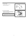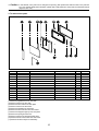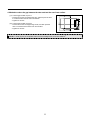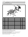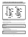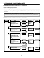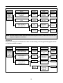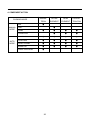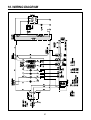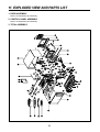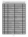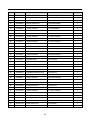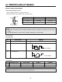
1
DAEWOO ELECTRONICS CORP.
686, AHYEON-DONG MAPO-GU SEOUL, KOREA
C.P.O. BOX 8003 SEOUL, KOREA
TELEX: DWELEC K28177-8
CABLE: “DAEWOOELEC”
S/M NO. :
PRINTED DATE: Nov. 2005
S/M No. : C8H4T7S001
Service Manual
Microwave Oven
Model: KOC-8H4T7S
✔ Caution
: In this Manual, some parts can be changed for improving,
their performance without notice in the parts list. So, if you
need the latest parts information, please refer to PPL(Parts
Price List) in Service Information Center (http://svc.dwe.co.kr).
Nov. 2005
PRECAUTIONS TO BE OBSERVED BEFORE AND
DURING SERVICING TO AVOID POSSIBLE
EXPOSURE TO EXCESSIVE MICROWAVE ENERGY
(a) Do not operate or allow the oven to be operated with the door open.
(b) Make the following safety checks on all ovens to be serviced before activating the magnetron or other
microwave source, and make repairs if necessary: (1) Interlock operation, (2) Proper door closing, (3)
Seal and sealing surfaces (arcing, wear, and other damage), (4) Damage to or loosening of hinges and
latches (5) Evidence of dropping or abuse.
(c) Before turning on power to the microwave oven for any service test or inspection within the microwave
generating compartments, check the magnetron, wave guide or transmission line, and cavity for proper
alignment, integrity, and connections.
(d) Any defective or misadjusted components in the interlock, monitor, door seal and microwave
generation and transmission systems shall be repaired, replaced, or adjusted by procedures described
in this manual before the oven is released to the owner.
TABLE OF CONTENTS
1. SAFETY AND PRECAUTIONS....................................................................................................................................2
2. SPECIFICATIONS ........................................................................................................................................................3
3. EXTERNAL VIEW.........................................................................................................................................................4
3-1. OUTER DIMENSION ..........................................................................................................................................4
3-2. FEATURE DIAGRAM .........................................................................................................................................5
4. INSTALLATION ............................................................................................................................................................6
5. CONTROL PANEL .......................................................................................................................................................7
6. DISASSEMBLY AND ASSEMBLY ..............................................................................................................................8
7. INTERLOCK MECHANISM AND ADJUSTMENT.....................................................................................................17
8. TROUBLE SHOOTING GUIDE ..................................................................................................................................18
9. MESUREMENT AND TEST .......................................................................................................................................23
9-1. MEASUREMENT OF THE MICROWAVE POWER OUTPUT ........................................................................23
9-2. MICROWAVE RADIATION TEST ....................................................................................................................24
9-3. COMPONENT TEST PROCEDURE................................................................................................................25
9-4. COMPONENT ACTION....................................................................................................................................26
10. WIRING DIAGRAM...................................................................................................................................................27
11. EXPLODED VIEW AND PARTS LIST .....................................................................................................................28
11-1. DOOR ASSEMBLY.........................................................................................................................................28
11-2. CONTROL PANEL ASSEMBLY.....................................................................................................................28
11-3. TOTAL ASSEMBLY........................................................................................................................................28
12. PRINTED CIRCUIT BOARD ....................................................................................................................................31
13. P.C.B CIRCUIT DIAGRAM.......................................................................................................................................36
1
1. SAFETY AND PRECAUTIONS
1. FOR SAFE OPERATION
Damage that allows the microwave energy (that cooks or heats the food) to escape will result in poor cooking and may
cause serious bodily injury to the operator.
IF ANY OF THE FOLLOWING CONDITIONS EXIST, OPERATOR MUST NOT USE THE APPLIANCE.
(Only a trained service personnel should make repairs.)
(1) A broken door hinge.
(2) A broken door viewing screen.
(3) A broken front panel, oven cavity.
(4) A loosened door lock.
(5) A broken door lock.
The door gasket plate and oven cavity surface should be kept clean.
No grease, soil or spatter should be allowed to build up on these surfaces or inside the oven.
DO NOT ATTEMPT TO OPERATE THIS APPLIANCE WITH THE DOOR OPEN.
The microwave oven has concealed switches to make sure the power is turned off when the door is opened.
Do not attempt to defeat them.
DO NOT ATTEMPT TO SERVICE THIS APPLIANCE UNTIL YOU HAVE READ THIS SERVICE MANUAL.
2. FOR SAFE SERVICE PROCEDURES.
1. If the oven is operative prior to servicing, a microwave emission check should be performed prior to servicing the
oven.
2. If any certified oven unit is found to servicing, a microwave emission check should be performed prior to servicing the
oven.
(1) inform the manufacturer, importer or assembler,
(2) repair the unit at no cost to the owner,
(3) attempt to ascertain the cause of the excessive leakage,
(4) tell the owner of the unit not to use the unit until the oven has been brought into compliance.
3. If the oven operates with the door open, the service person should tell the user not to operate the oven and contact
the manufacturer immediately.
IMPORTANT
The wire in this mains lead coloured in accordance with the following code.
Green-and-yellow : Earth
Blue
: Neutral
Brown
: Live
As the colours of the wires in the mains lead of this appliance may not correspond with the coloured markings
identifying the terminals in your plug, proceed as follows:
The wire which is coloured green-and-yellow must be connected to the terminal in the plug which is marked with the
letter E , earth symbol or coloured green-and-yellow.
The wire which is coloured blue must be connected to the terminal which is marked with the letter N or coloured
black.
The wire which is coloured brown must be connected to the terminal which is marked with the letter L or coloured
red.
NOTE : This oven is designed for counter-top use only.
2
2. SPECIFICATIONS
MODEL
KOC-8H4T7S
POWER SUPPLY
230V~50Hz, SINGLE PHASE WITH EARTHING
MICROWAVE
1400W
POWER
GRILL
850W
CONSUMPTION
CONVECTION
1850W
COMBINATION
2500W
MICROWAVE ENERGY OUTPUT
900W (IEC 705)
MICROWAVE FREQUENCY
2450MHz
OUTSIDE DIMENSIONS (W X H X D)
501X485.8X319mm(19.7X19.1X12.6 in.)
CAVITY DIMENSIONS (W X H X D)
310X320X229mm(12.2X12.6X9 in.)
NET WEIGHT
Approx. 18Kg (39.6 lbs.)
TIMER
60 minutes
FUNCTION SELECTIONS
Microwave / Grill / Convection / Combination
POWER SELECTIONS
10 LEVELS
CAVITY VOLUME
0.83 Cu. Ft
* SPECIFICATION ARE SUBJECT TO CHANGE WITHOUT NOTICE.
3
3. EXTERNAL VIEW
1. OUTER DIMENSION
485.8
319
501
4
2. FEATURE DIAGRAM
11. DOOR HOOK
When the door is closed, it will automatically lock shut. If door is opened while oven is operating, the magnetron
will immediately stop operating.
12.DOOR VIEWING SCREEN
Allows viewing of food. The screen is designed so that light can pass through, but not the microwave.
13. METAL RACK
14. TOP HEATER
Turns on when convection, grill and combi cooking is selected.
15. OVEN LAMP
Automatically turns on during oven operating.
16. SAFETY INTERLOCK SYSTEM
17. CONTROL PANEL
18. Glass Turntable
Turntable Center the tray on the roller guide when using the microwave features. Place food or microwave-safe
cookware directly on the glass turntable.
* NOTE : Glass Turntable is atteched to the right cushion.
19. Metal Tray
Put food or appropriate cookware directly on the metal tray and place on the glass turntable and then place on the
roller guide when using convection cooking, combination cooking, auto cooking or grill cooking.
10. ROLLER GUIDE
This must always be used for cooking together with the turntable tray.
11. COUPLER
This fits over the shaft in the center of the ovens cavity floor. This is to remain in the oven for all cooking.
12. CONVECTION OUTLET & FAN
13. OVEN FRONT PLATE
14. DOOR SEAL
Door seal maintains the microwave energy within the oven cavity and prevents microwave leakage.
5
4. INSTALLATION
1. Steady, flat location
This microwave oven should be set on a steady, flat surface.
This microwave oven is designed for counter top use only.
2. Leave space behind and side
All air vents should be kept a clearance. If all vents are covered during operation, the oven may overheat and, eventually,
cause failure.
3. Away from Radio and TV sets
Poor television reception and radio interference may result if the oven is located close to a TV, Radio, antenna or feeder
and so on.
Position the oven as far from them as possible.
4. Away from heating appliances and water taps
Keep the oven away from hot air, steam or splash when choosing a place to position it, or the insulation might be
adversely affected and breakdowns occur.
5. Power supply
Check your local power source. This microwave oven requires a current of approximately 11 amperes, 230V, 50Hz.
Power supply cord is about 1.0 meters long.
The voltage used must be the same as specified on this oven. Using a higher voltage may result in a fire or other
accident causing oven damage. Using low voltage will cause slow cooking. We are not responsible for damage
resulting from use of this oven with a voltage of ampere fuse other than those specified.
This appliance is supplied with cable of special type, which, if damaged, must be repaired with cable of same type.
Such a cable can be purchased from DAEWOO and must be installed by a Qualified Person.
6. Examine the oven after unpacking for any damage such as:
A misaligned door, broken door or a dent in cavity.
If any of the above are visible, DO NOT INSTALL, and notify dealer immediately.
7. Do not operate the oven if it is colder than room temperature.
EARTHING INSTRUCTIONS
This appliance must be earthed. In the event of an electrical short circuit, earthing reduces the risk of the electric shock by
providing an escape wire for the electric current. This appliance is equipped with a cord having a earthing wire with a
earthing plug. The plug must be plugged into an outlet that is properly installed and earthed.
WARNING
Improper use of the earthing plug can result in a risk of electric shock.
Consult a qualified electrician of serviceman if the earthing instructions are not completely understood, or if doubt
exists as to whether the appliance is properly earthed, and either:
If it is necessary to use an extension cord, use only a 3-wire extension cord that has a 3-blade earthing plug, and a
3-slot receptacle that will accept the plug on the appliance.
The marked rating of the extension cord should be equal to or greater than the electrical rating of the appliance, or
Do not use an extension cord.
6
5. CONTROL PANEL
1 Display : Cooking time, power level, indicators and
present time are displayed.
MW : When blinking, the oven is operating in
MICROWAVE COOK.
Grill : When blinking, the oven is operating in GRILL.
Combi : When blinking, the oven is operating in COMBI.
Defrost Weight : When blinking, the oven is operating in
WEIGHT DEFROST.
Time : When blinking, the oven is operating in TIME
DEFROST.
Auto-cook : When blinking, the oven is operating AUTO
COOK.
Lock : When lighting, the oven is CHILD LOCK.
Con-vection : When blinking, the oven is operating in
CONVECTION.
g : When blinking, the oven is operating in weight input
mode.
2 Auto cook : Used to cook or reheat.
3 Combi : Used to select combi.
4 Grill : Used to select grill.
5 MW : Used to set power level of micro wave.
6 Convection : Used to select convection and selected
temp.
7 Weight Defrost : Used to defrost foods.
8 Time Defrost : Used to defrost foods.
9 Clock : Used to set clock.
Stop / clear
0 STOP/CLEAR : Used to stop the oven operation or to
delete the cooking data.
Start /
speedy cook
q START/SPEEDY COOK : Used to start a programmed,
also for speedy start(each press adds 30 seconds
microwave cooking time).
w Dial knob : Used to set time, weight and quantity.
7
6. DISASSEMBLY AND ASSEMBLY
- Cautions to be observed when trouble shooting.
Unlike many other appliances, the microwave oven is high-voltage, high-current equipment. It is completely safe
during normal operation. However, carelessness in servicing the oven can result in an electric shock or possible
danger from a short circuit. You are asked to observe the following precautions carefully.
1. Always remove the power plug from the outlet before servicing.
2. Use an insulated screwdriver and wear rubber gloves when servicing the high voltage side.
3. Discharge the high voltage capacitor before touching any oven components or wiring.
(1) Check the grounding.
Do not operate on a two-wire extension cord.
The microwave oven is designed to be used while grounded.
It is imperative, therefore, to make sure it is grounded
properly before beginning repair work.
(2) Warning about the electric charge in the high voltage capacitor.
For about 30 seconds after the operation has stopped, electric
charge remains in the high voltage capacitor.
When replacing or checking parts, short between oven chassis
and the negative high terminal of the high voltage capacitor by
using a properly insulated screwdriver to discharge.
4. When the fuse is blown out due to the operation of the monitor
switch; replace primary interlock switch, secondary interlock switch
and interlock monitor switch.
5. After repair or replacement of parts, make sure that the screws are
properly tightened, and all electrical connections are tightened.
6. Do not operate without cabinet.
CAUTION : Service personnel should remove their watches whenever working close to or replacing the magnetron.
WARNING : When servicing the appliance, take care when touching or replacing high potential parts because of
electrical shock or exposing microwave. These parts are as follows - HV Transformer, Magnetron,
HV Capacitor, HV Diode.
8
1. To remove cabinet
1) Remove four screws on cabinet back.
2) Push the cabinet backward.
2. To remove door assembly
1) Remove two screws which secure the stopper hinge top.
2) Remove the door assembly from top plate of cavity.
3) Reverse the above for assemby.
NOTE: After replacing the door assembly, perform a check
of correct alignment with the hinge and cavity front
plate.
9
✔ Caution : In this Manual, some parts can be changed for improving, their performance without notice in the parts list.
So, if you need the latest parts information, please refer to PPL(Parts Price List) in Service Information Center
(http://svc.dwe.co.kr).
3. To remove door parts.
REF NO.
A01
A02
A03
A04
A05
A06
A07
A08
A09
A10
A11
A12
A13
PART CODE
3516601400
3513101310
3515101310
3512209910
3511616300
3517009500
3510610600
7122401211
3512606700
7001401211
3512301310
3515203600
712140061
PART NAME
DOOR-PLATE
HOOK
SPRING HOOK
FRAME DOOR
DECORATOR DOOR
BARRIER-SCREEN *O
SUPPORTER BRACKEK GLASS
SCREW TAPPING
HANDLE DOOR
SCREW MACHINE
GASKET DOOR
STOPPER HINGE *T AS
SCREW TAPPING
(1) Remove the gasket door from door plate.
(2) Remove screws from door plate.
(3) Remove the door frame from door plate.
(4) Remove screws from door frame.
(5) Remove the handle from door frame.
(6) Remove the decorator door from door frame.
(7) Remove the stopper hinge top from door plate.
(8) Remove the spring and the hook.
(9) Remove screws from supporter braket glass.
(10) Remove barrier screen outer from door frame.
(11) Reverse the above steps for reassembly.
10
DESCRIPTION
SBHG-1A T0.7
POM
HSW-3
ABS SR0320
STS430 T0.5 HL
MIRROR T3.2
SBHG T0.8
T2S TRS 4X12 MFZN
AL
PAN M4XL12 MFZN
PP
KOC-970T1S
T2S PAN 4X6 MFZN
Q’TY
1
1
1
1
1
1
1
2
1
2
1
1
1
REMARK
4. Method to reduce the gap between the door seal and the oven front surface.
(1) To reduce gap located on part ‘A’.
• Loosen two screws on stopper hinge top, and then push the door
to contact the door seal to oven front surface.
• Tighten two screws.
(2) To reduce gap located on part ‘B’.
• Loosen two screws on stopper hinge under, and then push the
door to contact the door seal to oven front surface.
• Tighten two screws.
NOTE : A small gap may be acceptable if the microwave leakage does not exceed 4mW/cm2.
11
✔ Caution : In this Manual, some parts can be changed for improving, their performance without notice in the parts list.
So, if you need the latest parts information, please refer to PPL(Parts Price List) in Service Information Center
(http://svc.dwe.co.kr).
5. To remove control panel parts.
REF NO.
B01
B02
B03
B04
B05
B06
B07
B08
B09
B10
B11
PART CODE
3516734500
3511616200
3516006400
3515502500
3516915000
3516915100
3513408900
7122401211
7621301011
PKMPMSGG00
PKBPMSGG00
PART NAME
CONTROL-PANEL
DECORATOR C-PANEL
SPEICAL DOUBLE TAPE
WINDOW DISPLAY
BUTTON FUNCTI0N-A
BUTTON FUNCTI0N-B
KNOB VOLUME
SCREW TAPPING
SCREW TAPPING
PCB MAIN MANUAL AS
PCB BUTTON MANUAL AS
DESCRIPTION
ABS SG-076OD SG-175
STS430 T0.5 HL
KOC-8H4T7S
PMMA IF-850
ABS SG-076OD SG-175
ABS SG-076OD SG-175
ABS SG-076OD SG-175
T2S TRS 4X12 MFZN
T2 PAN 3X10 PW MFZN
KOC-8H4T7S
KOC-8H4T7S
Q’TY
1
1
1
1
1
1
1
4
8
1
1
REMARK
(1) Remove the screw which secure the control panel, push up two snap fits and draw forward the control panel assembly.
(2) Remove four screws(B08) which secure the PCB Main ASS°ØY.
(3) Pull out the Main PCB assembly(B10).
(4) Remove eight screws(B09) which secure the PCB Sub ASS°ØY.
(5) Pull out the Sub PCB assembly(B11).
(6) Pull out the Knob volume(B07) from the Sub PCB assembly.
(7) Pull out ten buttons from the control panel.
(8) Pull out Decorator control panel(B01) from the control panel.
(9) Pull out Window display(B04) from the control panel.
(10)Reverse the above steps for reassembly.
12
6. To remove high voltage capacitor.
1) Remove a screw which secure the grounding ring
terminal of the H.V. diode and the capacitor holder.
2) Remove the H.V. diode from the capacitor holder.
3) Reverse the above steps for reassembly.
High voltage circuit wiring
7. To remove magnetron.
1) Remove a screw which secure the magnetron.
2) Remove the magnetron.
3) Reverse the above steps for reassembly.
CAUTION : Never install the magnetron without the metallic gasket plate which is packed with each magnetron to
prevent microwave leakage. Whenever repair work is carried out on magnetron, check the microwave
leakage. It shall not exceed 4mW/cm2 for a fully assembled oven with door normally closed.
Metallic
gasket
plate
Cooling fin
Magnetron
antenna
Filament
terminal
<MAGNETRON>
13
8. To remove wind guide assembly.
1) Remove a screw for earthing.
2) Remove the noise filter from the wind guide.
3) Remove a screw which secure the wind guide assembly.
4) Draw forward the wind guide assembly.
5) Pull the fan from the motor shaft.
6) Remove two screws which secure the motor shaded pole.
7) Remove the motor shaded pole.
8) Reverse the above steps for reasembly.
9. To remove H.V.transformer.
1) Remove four screws holding the H.V.transformer.
2) Remove the H.V.transformer.
3) Reverse the above steps for reassembly.
14
✔ Caution : In this Manual, some parts can be changed for improving, their performance without notice in the parts list.
So, if you need the latest parts information, please refer to PPL(Parts Price List) in Service Information Center
(http://svc.dwe.co.kr).
10. To remove Top heater assembly parts.
REF NO.
1
2
3
4
5
6
7
8
PART CODE
3512805800
3512806900
7113400814
3511412400
3510610500
7112401011
3512523600
7112401011
PART NAME
HEATER MIRACLON
HEATER REFLECTOR
SCREW TAPPING
COVER HEATER *T
BRACKET COVER HEATER
SCREW TAPPING
GUIDE AIR OUTLET
SCREW TAPPING
1) Remove a screw 8 and pull out Guide air outlet 7 .
2) Remove screws 6 and pull out braket cover heater 5 .
3) Pull out heater miraclon 1 .
4) Remove two screws 3 .
5) Pull out the heater reflector 2 from cover heater *T 4 .
6) Reverse the above steps for reassembly.
15
DESCRIPTION
230V 800W 270MM
STS430 T0.5
T1 BIN 4X8 MFNI
SA1D-80 T0.4
SECC T0.5
T1 TRS 4*10 MFZN
SBHG T0.5
T1 TRS 4*10 MFZN
Q’TY
1
1
2
1
1
1
1
1
REMARK
✔ Caution : In this Manual, some parts can be changed for improving, their performance without notice in the parts list.
So, if you need the latest parts information, please refer to PPL(Parts Price List) in Service Information Center
(http://svc.dwe.co.kr).
11. To remove Rear heater assembly parts.
REF NO.
1
2
3
4
5
6
7
8
9
10
11
12
13
14
15
16
17
18
PART CODE
3511412500
3963514330
3512807310
3513303900
7601400811
7113400814
7400104011
3511800700
7S627W40X1
3511800900
3512782600
3512782610
7402704600
7122400611
3511412600
3511410500
7272400811
7112401011
PART NAME
COVER HEATER *B
MOTOR SHADED POLE
HEATER QUARTZ
INSULATOR HEATER *B
SCREW MACHINE
SCREW TAPPING
WASHER PLAIN
FAN CONVECTION
SPECIAL SCREW
FAN
HARNESS CONVECTION *A
HARNESS CONVECTION *B
RING C
SCREW TAPPING
COVER *B
COVER MOTOR *B
SCREW TAPTITE
SCREW TAPPING
DESCRIPTION
SA1D-80 T0.5
230V 50HZ MW10CA-T03
115V 500W 240MM A
SBHG-1 T0.6
PAN 4X8 PW MFZN
T1 BIN 4X8 MFNI
PW-1-4 MFZN
SA1D-80 T0.5
NUT FLANGE M4 MFZN
PBT
KOC-8H5T7S
KOC-8H5T7S
CR-5 SK5
T2S TRS 4X6 MFZN
SBHG-3 T0.4
SA1D-80 T0.5
TT3 TRS 4X8 MFZN
T1 TRS 4*10 MFZN
1) Remove a screw 17 and pull out Cover motor *B 16.
2) Remove a screw 18 and pull out Cover *B 15 .
3) Pull out the Harness convection-A 11 and Harness convection-B 12 .
4) Remove four screws 14 and then pull out the Rear heater assembly.
5) Remove a Nut 9 and the pull out the Fan convection 8 .
6) Remove three screws 6 and then separate the Cover heater *B 1 and the lnsulator heater *B 4 .
7) Pull out the Heater 3 from the Cover Heater *B 1 .
8) Remove two screw 5 and then separate the lnsulator heater *B 1 and Motor shaded pole 2 .
9) Remove the C-Ring 13 and then pull out the Fan 10 from Motor shaft.
10)Reverse the above steps for reassebly.
16
Q’TY
1
1
2
1
2
3
1
1
1
1
1
1
1
4
1
1
1
1
REMARK
7. INTERLOCK MECHANISM AND ADJUSTMENT
The door lock mechanism is a device which has been specially designed to completely eliminate microwave radiation when
the door is opened during operation, and thus to perfectly prevent the danger resulting from the leakage of microwave.
(1) Primary interlock switch
When the door is closed, the hook locks the oven door. If the door is not closed properly, the oven will not operate.
When the door is closed, the hook pushes the button of the microswitch. Then the button of the primary interlock switch
bring it under ON condition. (No position)
(2) DOM switch and interlock monitor switch
When the door is closed, the hook pushes the lock lever downward. The lock lever presses the button of the interlock
monitor switch to bring it under OFF condition (No position) and presses the button of the DOM switch to bring it under
ON condition. (No position)
ADJUSTMENT :
Interlock monitor switch
When the door is closed, the interlock monitor switch should be opened (No position) before other switches are closed.
When the door is opened, the interlock monitor switch should be closed (No position) after other switches are opened.
(3) Adjustment steps
a) Loosen the one mounting screw.
b) Adjust interlock switch assembly position.
c) Make sure that lock lever moves smoothly after adjustment is completed.
d) Tighten completely two mounting screws.
NOTE :
Microwave emission test should be performed after adjusting interlock mechanism.
If the microwave emission exceed 4mW/cm2, readjust interlock mechanism.
17
8. TROUBLE SHOOTING GUIDE
Following the procedure below to check if the oven is defective or not.
1) Check grounding before trouble checking.
2) Be careful of the high voltage circuit.
3) Discharge the high voltage capacitor.
4) When checking the continuity of the switches, fuse or high voltage tranformer, disconnect one load wire from these
parts and check continuity with the AC plug removed. To do otherwise may result in a false reading or damage to
your meter.
NOTE : When electric parts are checked, be sure the power cord is not inserted the wall outlet.
Check wire harness, wiring and connection of the terminals and power cord before check the parts listed below.
(TROUBLE 1) Oven does not operate at all : any inputs can not be accepted.
CONDITION
Fuse blows.
CHECK
Check continuity of
interlock monitor switch with
door closed
( COM NC )
RESULT
Continuity
(COM NC)
CAUSE
Malfunction of
Interlock
monitor switch
REMEDY
Replace
No continuity
No
Continuity
Check continuity of
primary an interlock switch
with door closed
Malfunction of
interlock switch
Replace
Continuity
Continuity
Check continuity of
primary interlock switch contact
with door partially open until
interlock monitor switch contact
close
( COM NC close )
Check continuity of
primary winding of low voltage
transformer
or infinite
Approx.
480 ~620
( normal )
Fuse again
blows
Disconnect high voltage
fuse and operate the unit
18
Shorted contacts
of primary
interlock Switch
Defective low
voltage
transformer
Defective
high voltage
transformer
Replace
Replace
Replace
CONDITION
CHECK
RESULT
CAUSE
REMEDY
Outlet has
proper
voltage
fuse does not
blow?
Check continuity of
magnetron
No
continuity
Defective
magnetron.
Replace
Check continuity of noise filter
board
No
continuity
Defective line
filter board
Replace
Check continuity of
power supply cord
No
continuity
Open power
supply cord
Replace
No
continuity
Defective touch
control circuit
Replace
NOTE : All these switches must be replaced at the same time, please refer to (7.Interlock mechanism and
adjust) for adjustment instructions
(TROUBLE 2)
Display shows all figures selected, but oven does not start cooking, even though desired program and time
are set and start button is tapped.
CONDITION
CHECK
RESULT
CAUSE
REMEDY
Turn table
motor and
oven lamp
do
not turn on
Check continuity of
primary interlock switch
No
continuity
Malfunction of
primary interlock
switch
Adjust or
replace
Check continuity of
D.O.M switch
No
continuity
Check D.C voltage
being supplied to
RELAY(RY4) coil
0V
Defective touch
control Circuit
Replace
Approx.
24V DC
Fault contacts
of RELAY
(RY4) or open
relay coil.
Replace
19
Malfunction of
D.O.M switch
Adjust or
replace
TROUBLE 3) No microwave oscillation even though fan motor rotates.
CONDITION
CHECK
RESULT
CAUSE
REMEDY
No
microwave
oscillation
Check continuity of
high voltage fuse
No
continuity
Defective
high voltage
fuse
Replace
Check continuity of
high voltage capacitor terminals
with wires removed
Continuity
Defective
high voltage
transformer
1
Check continuity of
high voltage rectifier in forward
and backward
direction with DC megger
Continuity
in backward
direction
Defective high
voltage rectifier
Replace
No microwave oscillation
Connect megger leads to
magnetron terminal and
magnetron body
Continuity
Defective
magnetron
2
Check D.C voltage
being supplied to
RELAY (RY1) coil
0V
Defective
touch control
circuit
Replace
Approx.
24V DC
Faulty contacts of
RELAY
(RY1) or open
relay coil
Replace
Defective
high voltage
transformer
Replace
Defective high
voltage
transformer
Replace
Defective
magnetron
Replace
0
1 Check resistance of primary
or
and secondary coil of high
voltage transformer
1 Check continuity of filament
No continuity
terminal of high voltage
transformer
2 Check continuity of
magnetron heater with wires
removed
No continuity
20
(TROUBLE 4)
Grill heater (upper heater) is not heated; food will not become hot.
CONDITION
Grill heater is
not heated.
CHECK
RESULT
CAUSE
REMEDY
Check continuity of
primary interlock switch
No
continuity
Malfunction of
primary Interlock
switch
Adjust or
replace
Check continuity of
DOM switch
No
continuity
Malfunction of
DOM switch
Check continuity of
heater
No
continuity
Defective heater
Check D.C voltage
being supplied to
RELAY (RY2) coil
0V
Defective touch
control circuit
Replace
Approx.
24V DC
Faulty contacts of
RELAY
(RY2) or open
relay coil
Replace
Adjust or
replace
Replace
(TROUBLE 5)
1) Convection heater is not heated; food will not become hot.
2) Convection fan motor does no rotate.
CONDITION
CHECK
RESULT
CAUSE
REMEDY
1)Convection
heater is not
heated.
2)Convection
fan and
motor does
not rotate.
Check continuity of
primary interlock switch
No
continuity
Malfunction of
primary Interlock
switch
Adjust or
replace
Check continuity of
DOM switch
No
continuity
Check continuity of
(heater or motor)
No
continuity
Defective heater
or motor
Replace
Check D.C voltage
being supplied to
RELAY (RY3, RY6) coil
0V
Defective touch
control circuit
Replace
Approx.
24V DC
Faulty contacts of
RELAY
(RY3,RY6) or
open relay coil
Replace
21
Malfunction of
DOM switch
Adjust or
replace
(TROUBLE 6)
The following visual conditions inditions indicate a probable defective touch control Circuit or button P.C.B.
assembly
1. Incomplete segments.
1) segment missing
2) partial segments missing
3) digit flickering other than normal fluorescent slight flickering
2. A distinct change in the brightness of one or more numbers exists in the
display.
3. One or more digits in the display are not on when they should be.
4. Display does not count down or up with time cooking or clock operation.
5. Oven is programmable and cooks normally but no display shows.
6. Display obviously jumps in time while counting down.
7. Display counts down noticeably too fast while cooking.
8. Display does not show the time of day when clear button is touched.
9. Oven lamp and turn table motor do not stop although cooking is finished.
Check if the RELAY(RY4) contacts close and if they are close, replace touch control circuit.
CONDITION
CHECK
Display does
not show
programming
at all, even if
keyboard is
touched.
Check each button for
continuity of the button
RESULT
CAUSE
REMEDY
Malfunction of sub
pcb assembly
Replace
control box
sub-assembly
CAUSE
REMEDY
Replace
Replace
No
continuty
Defective
heater
Replace
continuity
Defective touch
control circuit
Replace
Normal
(TROUBLE 7)
When ERROR 2 ERROR 3 come on display.
CONDITION
CHECK
ERROR 2 &
ERROR 3
come on
display
Check continuity of thermistor
(resistance of thermistor)
RESULT
0
or infinite
Approx
200~300k
(room
temperature)
Check continuity of heater
(convection, upper)
22
9. MEASUREMENT AND TEST
1. MEASUREMENT OF THE MICROWAVE POWER OUTPUT
Microwave output power can be checked by indirectly measuring the temperature rise of a certain amount of water
exposed to the microwave as directed below.
PROCEDURE
1. A cylindrical container of borosilicate glass is used for the test. It has a maximum thickness of 3mm, an external
diameter of approximately 190mm and a height of approximately 90mm.
The mass of the container is determined.
2. At the start of the test, the oven and the empty container are at ambient temperature. Water having an initial
temperature of 10 C 1 C is used for the test. The water temperature is measured immediately before it is poured
into the container.
3. A quantity of 1000g 5g of water is added to the container and its actual mass obtained.
The container is then immediately placed in the centre
of the oven shelf, which is in its lowest normal position.
The oven is operated and the time for the water
temperature to attain 20 C 2 C is measured. The
oven is then switched off and the final water
temperature is measured within 60s.
NOTE 1 - The water stirred is before its temperature is
measured.
NOTE 2 - Stirring and measuring devices are to have a
low heat capacity.
4. The microwave power output is calculated from the
formula
P = 4,187 mW (T2 -T1) + 0.55 mC(T2 - T0)/t
where
P is the microwave power output, in watts ;
mW is the mass of the water, in grams ;
mc is the mass of the container, in grams ;
T0 is ambient temperature, in degrees Celsius ;
T1 is the initial temperature of the water, in degree Celsius ;
T2 is the final temperature of the water, in degrees Celsius ;
t is the heating time, in seconds, excluding the magnetron filament heating-up time.
The microwave power output is stated in watts, rounded off to the nearest 50W
CAUTION
1. Water load should be measured exactly to 1 liter.
2. Input power voltage should be exactly specified voltage (Refer to SPECIFICATIONS).
3. Ambient temperature should be 20 2 C (68 3.6 F)
Heating time for power output: (T2 = T0)
A (second)
70
64
60
56
52
49
47
44
42
40
38
B (W)
600
650
700
750
800
850
900
950
1000
1050
1100
23
2. MICROWAVE RADIATION TEST
WARNING
1. Make sure to check the microwave leakage before and after repair of adjustment.
2. Always start measuring of an unknown field to assure safety for operating personnel from microwave energy.
3. Do not place your hands into any suspected microwave radiation field unless the safe density level is known.
4. Care should be taken not to place the eyes in direct line with the source of microwave energy.
5. Slowly approach the unit under test until the radiometer reads an appreciable microwave leakage from the
unit under the test.
PROCEDURE
1. Prepare Microwave Energy Survey Meter, 600cc glass beaker,
and glass thermometer 100 C (212 F).
2. Pour 275cc 15cc of tap water initially at 20 5 C (68 9 F) in
the 600 cc glass beaker with an inside diameter of approx. 95
mm(3.5 in.).
3. Place it at the center of the tray and set it in a cavity.
4. Close the door and operate the oven.
5. Measure the leakage by using Microwave Energy Survey Meter
with dual ranges, set to 2450MHz.
1) Measured radiation leakage must not exceed the value
prescribed below. Leakage for a fully assembled oven with
door normally closed must be less than 4mW/Cm2.
2) When measuring the leakage, always use the 5 cm (2 in.)
space cone with probe. Hold the probe perpendicular to the
cabinet and door. Place the space cone of the probe on the
door, cabinet, door seem, door viewing screen, the exhaust air vents and the suction air vents.
3) Measuring should be in a counter-clockwise direction at a rate of 1 in./sec. If the leakage of the cabinet door
seem is unknown, move the probe more slowly.
4) When measuring near a corner of the door, keep the probe perpendicular to the areas making sure the probe
end at the base of the cone does not get closer than 2 in. from any metal. If it does not, erroneous reading may
result.
24
3. COMPONENT TEST PROCEDURE
High voltage is present at the high voltage terminal of the high voltage transformer during any cooking cycle.
It is neither necessary nor advisable to attempt measurement of the high voltage.
Before touching any oven components or wiring, always unplug the oven from its power source and discharge the
capacitor.
1. High voltage transformer
1) Remove connections from the transformer terminals and check continuity.
2) Normal readings should be as follows :
Secondary winding ... Approx. 146 10%
Filament winding ... Approx. 0
Primary winding ... Approx. 2
2. High voltage capacitor
1) Check continuity of capacitor with meter on the highest OHM scale.
2) A normal capacitor will show continuity for a short time, and then indicate 10M
3) A shorted capacitor will show continuous continuity.
4) An open capacitor will show constant 10M .
5) Resistance between each terminal and chassis should be infinite.
once the capacitor charged.
3. High voltage diode
1) Isolate the diode from the circuit by disconnecting the leads.
2) With the ohmmeter set on the highest resistance scale measure the resistance across the diode terminals.
Reverse the meter leads and again observe the resistance reading. Meter with 6V, 9V or higher voltage batteries
should be used to check the front-back resistance of the diode, otherwise an infinite resistance may be read in
both directions. A normal diode’s resistance will be infinite in one direction and several hundred k in the other
direction.
4. Magnetron
For complete magnetron diagnosis, refer to "Measurement of the Microwave Power Output." Continuity checks can
only indicate and open filament or a shorted magnetron. To diagnose for an open filament or a shorted magnetron,
1) Isolate magnetron from the circuit by disconnecting the leads.
2) A continuity check across magnetron filament terminals should indicate 0.1 or less.
3) A continuity check between each filament terminal and magnetron case should read open.
5. Fuse
If the fuse in the primary and monitor switch circuit is blown when the door is opened, check the primary and
monitor switch before replacing the blown fuse. In case the fuse is blown by an improper switch operation, replace
the defective switch and fuse at the same time. Replace just the fuse if the switches operate normally.
25
4. COMPONENT ACTION
COOKING MODE
M/W
MANUAL
MODE
MAGNE-
UPPER
REAR
CONVEC-
TRON
ELEMENT
ELEMENT
TION FAN
●
●
●
●
●
●
●
●
GRILL
COMBI
●
CONVECTION
AUTO
MODE
ROAST PORK
●
●
●
●
ROAST BEEF
●
●
●
●
ROAST CHICKEN
●
●
●
●
BAKED FISH
●
●
●
●
FRESH VEGETABLES
●
26
10. WIRING DIAGRAM
27
11. EXPLODED VIEW AND PARTS LIST
1. DOOR ASSEMBLY
Refer to 6. Disassembly and assembly.
2. CONTROL PANEL ASSEMBLY
Refer to 6. Disassembly and assembly.
3. TOTAL ASSEMBLY
28
✔ Caution : In this Manual, some parts can be changed for improving, their performance without notice in the parts list.
So, if you need the latest parts information, please refer to PPL(Parts Price List) in Service Information Center
(http://svc.dwe.co.kr).
NO
PART CORD
PART NAME
DESCRIPTION
1
3516118500
CAVITY AS
KOC-8H5T7S
1
2
3511403800
COVER WAVE GUIDE
MICA T0.35
1
3
3517400610
COUPLER
TEFLON
1
4
3966031700
MOTOR SYNCRO
220/240V 50/60HZ SM16 HK36M6F6
1
5
7121400611
SCREW TAPPING
T2S PAN 4X6 MFZN
1
6
3514801600
SENSOR TEMPERATURE
MWS-DWM-0010-0
1
7
7S422X4081
SCREW SPECIAL
TT3 TRS 4X8 SE MFZN
1
8
3512782620
HARNESS MAIN
KOC-8H5T7S
1
9
3513811750
LOCK
CHEIL(FH-44N)
1
10
3513702620
LEVER LOCK
POM
1
11
4415A17352
SW MICRO
VP-533A-OF SPNO #187 200G
1
12
4415A66910
SW MICRO
VP-531A-OF/SZM-V16-FA-61
1
13
3518571000
SWITCH PUSH
MP101C
1
14
3513601600
LAMP
BL 240V 25W T25 C7A H187
1
15
3510311000
BASE
SBHG-1 T0.7
1
16
3512101400
FOOT
DASF-310
4
17
3518303401
CAPACITOR HV
2100VAC 1.05UF #187
1
18
3513001900
HOLDER HV CAPACITOR
SECC T0.8
1
19
3518401300
DIODE HV
CL01-12
1
20
7272400811
SCREW TAPTITE
TT3 TRS 4X8 MFZN
1
21
3518701400
FUSE HV
5KV 0.7A
1
22
3515202800
STOPPER HINGE *U AS
KOR-121M0A
1
23
7112401011
SCREW TAPPING
T1 TRS 4*10 MFZN
5
24
3518122800
TRANS HV
R1S592 ES00
1
25
3516003700
SPECIAL SCREW
TT3 HEX 4X8 FLG MFZN
4
26
PKCPSWGG00
CONTROL-PANEL AS
KOC-8H4T7S
1
27
3515305000
SUPPORTER WIRE
SWRH MFZN
1
28
7122401211
SCREW TAPPING
T2S TRS 4X12 MFZN
1
29
3511726410
DOOR AS
KOC-8H4T7S
1
30
3516003700
SPECIAL SCREW
TT3 HEX 4X8 FLG MFZN
2
31
3512524100
GUIDE WIND
PP GP-3152F FH44N NC
1
32
3963512320
MOTOR SHADED POLE
230V 20W MW10CA-M03
1
33
7121402511
SCREW TAPPING
T2S PAN 4X25 MFZN
2
34
3511800300
FAN
PP+30%GLASS
1
35
3518606100
NOISE-FILTER
DWLF-M13
1
36
7122401211
SCREW TAPPING
T2S TRS 4X12 MFZN
1
37
35113A5QJ5
CORD POWER AS
3X1.5 80X80 120-RTML 1.4M
1
29
Q'TY
NO
PART CORD
PART NAME
DESCRIPTION
38
7112401011
SCREW TAPPING
T1 TRS 4*10 MFZN
2
39
3518003700
MAGNETRON
2M218JFL 6CF
1
40
3516004000
SPECIAL SCREW
T2 BOLT FLANGE 5X12 DACRO
1
41
3512805800
HEATER MIRACLON
230V 800W 270MM
1
42
3512806900
HEATER REFLECTOR
STS430 T0.5
1
43
7113400814
SCREW TAPPING
T1 BIN 4X8 MFNI
2
44
3511412400
COVER HEATER *T
SA1D-80 T0.4
1
45
3510610500
BRACKET COVER HEATER
SECC T0.5
1
46
7112401011
SCREW TAPPING
T1 TRS 4*10 MFZN
1
47
3512523600
GUIDE AIR OUTLET
SBHG T0.5
1
48
7112401011
SCREW TAPPING
T1 TRS 4*10 MFZN
1
49
3511412500
COVER HEATER *B
SA1D-80 T0.5
1
50
3963514330
MOTOR SHADED POLE
230V 50HZ MW10CA-T03
1
51
3512807310
HEATER QUARTZ
115V 500W 240MM A
2
52
3513303900
INSULATOR HEATER *B
SBHG-1 T0.6
1
53
7601400811
SCREW MACHINE
PAN 4X8 PW MFZN
2
54
7113400814
SCREW TAPPING
T1 BIN 4X8 MFNI
3
55
7400104011
WASHER PLAIN
PW-1-4 MFZN
1
56
3511800700
FAN CONVECTION
SA1D-80 T0.5
1
57
7S627W40X1
SPECIAL SCREW
NUT FLANGE M4 MFZN
1
58
3511800900
FAN
PBT
1
59
3512782600
HARNESS CONVECTION *A
KOC-8H5T7S
1
60
3512782610
HARNESS CONVECTION *B
KOC-8H5T7S
1
61
7402704600
RING C
CR-5 SK5
1
62
7122400611
SCREW TAPPING
T2S TRS 4X6 MFZN
4
63
3518907400
THERMOSTAT
OFF:160 ON:0 V #187
1
64
3511412600
COVER *B
SBHG-3 T0.4
1
65
3511410500
COVER MOTOR *B
SA1D-80 T0.5
1
66
7272400811
SCREW TAPTITE
TT3 TRS 4X8 MFZN
1
67
7112401011
SCREW TAPPING
T1 TRS 4*10 MFZN
1
68
3510806400
CABINET AS
KOC-871C0S
1
69
7112401011
SCREW TAPPING
T1 TRS 4*10 MFZN
4
70
3517201951
TRAY RACK AS
KOR-17551S 30MM
1
71
3517210900
TRAY METAL AS
KOC-624S0J
1
72
3512517100
GUIDE ROLLER AS
KOG-62150S
1
73
3517203610
TRAY
BORO-SI GLASS(NEG)
1
30
Q'TY
12. PRINTED CIRCUIT BOARD
CIRCUIT CHECK PROCEDURE
1. Low voltage transformer check
The low voltage transformer is located on the P.C.B.
Measuring condition: Input voltage: 230V / Frequency: 50Hz
Terminal
Voltage(load)
Voltage(no load)
6-7
AC 17.0 V
AC 19.9 V
8-9
AC 1.3 V
AC 1.6 V
9-10
AC 1.3 V
AC 1.6 V
2
NOTE
1. Secondary side voltage of the low voltage transformer changes in proportion to fluctuation of power source
voltage.
2. The allowable tolerance of the secondary voltage is within 5% of nominal voltage.
2. Voltage Check
- Key check point
NO
CHECK POINT
1
IC1 PIN 26, 27
2
IC1 PIN 28
REMARK
5VDC 5%
5V
0V
3
T
T : 20 ms(50Hz)
T
T : 250 ns(4MHz)
IC1 PIN 8 OR 9
5V
0V
- Check method
NO
MEASURE POINT
WAVE FORM
REMEDY
REMARK
1
MP1
DC 5V 5%
Replace ZD3, EC1
NO LOAD
2
MP2
DC 24V 20%
Replace D17-20, EC5
NO LOAD
NOTE: Each measure point must be measured with GND points.
31
MEASUREPOINT
32
3. Case of no microwave oscillation
1) When touching M/W button, oven lamp turns on and Fan motor and turntable rotate, and cook indicator in
display comes on.
*Cause: RELAY 1 does not operate.
B
A
30
D7
M/W
RY1
Q4
STATE
POINT A
POINT B
RELAY 1 ON
+5V DC
GND
RELAY 1 OFF
GND
+24V DC
2) When touching M/W button, oven lamp does not turn on and turntable motor does not rotate but cook indicator
in display comes on.
*Cause: RELAY 4 does not operate.
B
LAMP
TRAY
A
34
D13
RY4
Q10
STATE
POINT A
POINT B
RELAY 4 ON
+5V DC
GND
RELAY 4 OFF
GND
+24V DC
3) When touching M/W button, oven lamp turns on and fan motor does not rotate but cook indicator in
display comes on.
*Cause: RELAY 5 does not operate.
B
FAN
A
35
D14
RY5
Q9
STATE
POINT A
POINT B
RELAY 5 ON
+5V DC
GND
RELAY 5 OFF
GND
+24V DC
33
4. Case of no heating of top grill
When touching GRILL or COMBI button, oven lamp turns on and fan motor and turntable rotate, and cook indicator
in display comes on.
*Cause: RELAY 2 does not operate.
B
A
Q3
32
RY2
D8
R21
Q5
STATE
POINT A
POINT B
RELAY 2 ON
+5V DC
GND
RELAY 2 OFF
GND
+24V DC
5. Case of no heating of convection grill
When touching CONVECTION button, oven lamp turns on and Fan motor and turntable rotate and cook indicator
in display comes on.
*Cause: RELAY 3 does not operate.
B
A
Q7
33
RY3
D9
R24
Q7
STATE
POINT A
POINT B
RELAY 3 ON
+5V DC
GND
RELAY 3 OFF
GND
+24V DC
34
6. Case of no stopping of the count down timer
When the door is opened during operation, the count down timer does not stop.
A
+5V
B
+5V
D6
R13
2
CN2
1
15
R5
Q2
+24V
D.O.M SW
R7
C3
POINT
A
B
DOOR OPEN
OPEN
+5V DC
DOOR CLOSED
CLOSE
GND
STATE
CHECK NO
1
METHOD
Check the stage(ON,OFF) of the door open
monitor switch by resistance
measurement.
35
REMEDY
Replace door open monitor swith.
SJ1
SJ2
SJ3
SJ4
SJ5
SJ6
SJ7
SJ8
36
NOTE
1. WATTAGE FOR UNMARKED RESISTOR IS 1/6W.
2. TOLERANGE FOR UNMARKED RESISTOR IS ±5%.
M268(MAIN) : 3514331210
M269 (SUB) : 3514331310
13. P.C.B. CIRCUIT DIAGRAM
PCB ASS’Y PART LIST
NO
1
2
3
4
5
6
7
8
9
10
11
12
13
14
15
16
17
18
19
20
21
22
23
24
25
26
27
28
29
30
31
32
33
34
35
36
37
38
39
40
41
42
NAME
BUZZER
C CERA
C CERA
C ELECTRO
C ELECTRO
C ELECTRO
C ELECTRO
CONNECTOR WAFER
CONNECTOR WAFER
CONNECTOR FILM
CONNECTOR WAFER
DIODE
DIODE
DIODE ZENER
DIODE ZENER
DIODE ZENER
DISPLAY VFD
FOAM
PCB MAIN
R ARRAY
R ARRAY
R CARBON FILM
R CARBON FILM
R CARBON FILM
R CARBON FILM
R CARBON FILM
R CARBON FILM
R CARBON FILM
R CARBON FILM
R CARBON FILM
R CARBON FILM
R CARBON FILM
RESONATOR CERA
IC MICOM
IC RESET
TRANSISTOR
TRANSISTOR
TRANSISTOR
TRANS POWER
SW RELAY
SW RELAY
WIRE COPPER 7.5mm
SYMBOL
SPECIFICATION
BZ1
BM-20K
C4,C5,C9,C10,C11
102K 50V AXIAL
C1~C3,C6,C7,C8,C12,C13,C14
104Z 50V AXIAL
EC1
50V RS 10uF
EC2
50V RSS 100uF
EC3,4
50V RSS 220uF
EC5
35V RSS 1000uF
CN1
35312-0310
CN2
35313-0210
CN3
HLEM15S-1
CN4
35328-0610
D1~D10,D13~16
1N4148
D11,12,17~20
1N4004A
ZD1
UZ-3.9BSB
ZD2
UZ-24BSB
ZD3
UZ-5.6BSB
DP1
SVM-5MS06
SPONGE
CR 15TX50X11
M268
94.4x227
RA2
7P(6) 1/8 100K J
RA1,3
8P(7) 1/8 100K J
R31
1/2W 27 5%
R26~30, R32
1/2W 200 5%
R2
1/4W 6.8 5%
R13,R21,R24
1/6W 4.7K 5%
R3,R11,R12,R14,R25,R33,R22,R23 1/6W 1K 5%
R9,R7
1/6W 10K 5%
R5,R10
1/6W 47K 5%
R1,R6,R17,R18,R19,R20
1/6W 100K 5%
R8
1/6W 1M 5%
R16
1/4W 10K 1%
R15
1/4W 120K 1%
CR1
CRT4.00MS
IC1
GMS81C2020A
IC2
KIA7033AP
Q2
KTA-1266Y
Q1,Q4,Q5,Q7,Q9~Q12
KRC-106M
Q3,Q6,Q8
KTC-3198GR
LVT1
DMR-210FS
RY1~3
G5G-1A-DT 1C DC24V
RY4~6
CS11-24SH 1C 1P
J1,J3,J4,J10,J11,J12,J19~21,
1/0.52 TIN COATING
J23,J24,J26,J27
43 WIRE COPPER 10 mm J2,J9,J14~18,J22,J28~32
1/0.52 TIN COATING
44 WIRE COPPER 12.5mm J5~J8,J13,J25
1/0.52 TIN COATING
37
PART CODE Q'TY REMARK
3515600100
1
CCZB1H102K 5
CCZF1H104Z
9
CEXE1H100A 1
CEXF1H101V
1
CEXF1H221V
2
CEXF1V102V
1
30166M5030
1
30166M7020
1
4CW215RBD0 1
4CW3061MX0 1
DZN4148--14
DZN4004A-6
DZUZ3R9BSB 1
DZUZ24BSB1
DZUZ5R6BSB 1
DSVM5MS06- 1
3517306400
1
3514331210
1
RA-87X104J
1
RA-88X104J
2
RD-2Z270JS
1
RD-2Z201JS
6
RD-4Z689J1
RD-AZ472J3
RD-AZ102J8
RD-AZ103J2
RD-AZ473J2
RD-AZ104J6
RD-AZ105J1
RN-4Z1002F
1
RN-4Z1203F
1
5P4R00MTS1
150G2020A1
OTP
1K1A7033AP
1
TZTA1266Y1
TZRC106M-8
TZTC3198GR
3
5EPV041410
1
5SC0101124
3
5SC0101129
3
85801052GY
13
85801052GY
85801052GY
13
6
NO
NAME
45
WIRE FLAT
46
WIRE COPPER
47
PCB SUB
48
CONNECTOR FILM
49
SW TACT
50
SW ROTARY
51 WIRE COPPER 10mm
52 WIRE COPPER 12.5mm
SYMBOL
SPECIFICATION
15/90 WH C
1/0.52 TIN COATING
93x212
HLEM15R-1
KPT-1115AM
EC12E24204A8
1/0.52 TIN COATING
1/0.52 TIN COATING
WF1
SJ5,SJ7,SJ8
M269
CN101
SW101~110
SW111
J103
J101,J102
38
PART CODE Q'TY REMARK
WSJ-159007
1
85801052GY
3
3514331310
1
4CW215RBD0 1
5S50101Z93
10
5S10302005
1
85801052GY
1
85801052GY
2