1
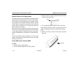
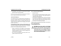
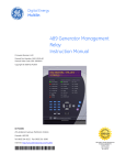
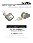
Medium Duty
Hybrid Electric
PACRI
P.O. Box 1518
Bellevue, WA 98009
Y53-6031
Operator’s Manual Supplement
Medium Duty Hybrid Electric System Supplemental
This supplement contains information that is not included in your current Operator's Manual. This supplement is in addition to the information contained in Eaton’s Hybrid Transmission Driver Instructions manual and applies to all vehicles
equipped with the Eaton diesel/electric hybrid powertrain.
(12/09)
Y53-6031
–1–
IMPORTANT SAFETY INFORMATION
MEDIUM DUTY HYBRID ELECTRIC SYSTEM SUPPLEMENTAL
Important Safety Information
Most accidents that involve the operation, maintenance or
repair of a vehicle or its components are caused by the
failure of a person to observe and follow basic safety
rules. Accidents can often be avoided by a person identifying and avoiding potentially hazardous situations. This
requires a person to constantly pay attention, be alert and
deliberate. The safety signals (Warning, Caution and
Note) in this manual and on the vehicle are not inclusive. It
is the responsibility of the operator to constantly be alert
for ANY condition which represents a potential safety hazard.
“WARNING”, “CAUTION”, or “NOTE”. Please do not
ignore any of these alerts.
WARNING
When you see this word, the message that follows is especially vital. It signals a potentially hazardous situation which, if not avoided, could result
in personal injury or death. This message will tell
you what the hazard is, what can happen if you
don't heed the warning, and how to avoid it.
Example:
WARNING! Never carry additional fuel containers in the vehicle. Such containers, full or
empty, may leak, explode or cause a fire in the
event of a collision. Failure to comply may
result in personal injury, death, equipment or
property damage.
Safety Signals
Alerting messages are in this manual. Please read and
follow them. They are included for your protection and
information. These messages can help you avoid injury to
yourself and others. In some cases, the information will
help prevent costly damage to your vehicle.
CAUTION
Key symbols and “signal words” are used to indicate what
kind of message is going to follow. Pay special attention to
instructions prefaced by symbols and signal words
–2–
Y53-6031
Signals a potentially hazardous situation which, if
not avoided, could result in property or vehicle
damage.
(12/09)
MEDIUM DUTY HYBRID ELECTRIC SYSTEM SUPPLEMENTAL
SAFETY SIGNALS
Example:
CAUTION: Continuing to operate your vehicle
with insufficient oil pressure will cause serious engine damage. Immediately shut off
your engine and determine the cause of the
problem. Failure to do so may result in equipment or property damage.
Please take the time to read these messages when
you see them, and remember:
WARNING!
Something that could injure you or could cause death.
CAUTION:
NOTE
Provides general information: for example, the
note could warn you on how drive the vehicle
more efficiently.
Something that could cause property or vehicle damage.
NOTE:
Useful information.
Example:
NOTE: Pumping the accelerator will not assist in
starting the engine.
(12/09)
Y53-6031
–3–
SYSTEM DESCRIPTION
HYBRID ELECTRIC SYSTEM
Hybrid Electric System
System Description
NOTE: Information provided in this supplemental
operator’s manual is intended to compliment the
Eaton Driver Instruction Manual. Any conflicting
details provided in Eaton’s Driver Instruction manual supersede information in this manual.
The hybrid system in this vehicle incorporates an electric
motor/generator that supplements the diesel engine to
improve fuel economy. Depending on the vehicle’s
intended service, this system may be comprised of (1) a
Hybrid Drive Unit, (2) a Power Electronics Carrier (PEC),
(3) a power inverter, (4) an optional DC/DC converter and
(5) a dedicated hybrid coolant fill tank. All of these components work in conjunction to supplement power from the
diesel engine.
4 (behind batteries)
3 (under step cover)
5
1
2
WARNING! Do not use the PEC as a step. Use
only the steps and handholds provided. Using
the PEC as a step may result in personal
injury and/or equipment damage.
–4–
Y53-6031
(12/09)
HYBRID ELECTRIC SYSTEM
OPERATION
Operation
Operating a hybrid vehicle is not much different than operating a conventional diesel engine while starting vehicle.
In most cases, the hybrid electric motor will crank the
engine. Operators may notice a slight delay between turning the key and the engine cranking. The vehicle also has
a 12V starter to start the vehicle in situations where the
hybrid system is not able to provide power to the vehicle.
Once the engine is started and idling, it will remain idling
until the load demands more torque (via accelerator
pedal) than what the electric motor is able to provide. In
some situations, the batteries may not be sufficiently
charged to provide the necessary torque. In these situations, the engine speed will increase to provide torque.
Batteries may also be charged while coasting, slowing
down and full braking (in Drive or Reverse). This process
is called regenerative braking. An operator will detect
regenerative braking because the vehicle will coast as if
the vehicle is moving up a grade. The system will disengage regenerative braking once the batteries are at full
charge.
(12/09)
WARNING! Be prepared to apply service
brakes with the foot pedal when the system
disengages the regenerative braking. Failure
to do so may result in a loss of vehicle control
which could lead to an accident involving
death or personal injury.
There may be times when regenerative braking does not
provide enough energy to charge the batteries. In these
situations, the hybrid system computer will optimize the
use of diesel engine energy to charge the batteries. A
vehicle that is idling, except when in ePTO mode (see next
paragraph), will not charge the hybrid system batteries.
NOTE: The hybrid system battery performance
may be affected by outside temperature and
extensive (greater than 6 months) storage without
charging. Refer to “340 Volt PEC Batteries” on
page 13 for maintenance instructions to follow if
the vehicle will not be used for extended periods
longer than 6 months.
Depending on the vehicle’s configuration, the hybrid
system may have an ePTO mode. In this mode, the
operator will be able to operate equipment without using
the engine. When ePTO mode is engaged, the engine will
Y53-6031
–5–
OPERATOR INTERFACE
HYBRID ELECTRIC SYSTEM
automatically turn on and off to charge the hybrid system
batteries.
Operator Interface
Transmission Controls*
NOTE: The ePTO mode will only engage when the
hood is in the closed position and the park brake is
applied. Refer to the Eaton Driver Instruction Manual for more details regarding ePTO operation.
HYBRID SYSTEM MONITOR
Some vehicles may be equipped with a PTO that is
driven by the engine only. These PTO’s are separate from
the hybrid system and the engine will run continuously
regardless of battery state of charge.
ELEC
MOTOR
ePTO
MPG
CHECK
HYBRID
STOP
HYBRID
DATA
FAILURE
Hybrid Display
Dash Panel
* This is a generic respresenation.
The actual transmission control
panel may be different than shown.
The operator has access to system information through a
dedicated screen display located on the dash. After the
vehicle progresses through the Power On Self Test
(POST), the display will provide the user with the following
real time information:
•
•
•
•
–6–
Y53-6031
Hybrid system mode
Dynamic fuel economy
Battery charge status
Warnings and Alerts
(12/09)
HYBRID ELECTRIC SYSTEM
OPERATOR INTERFACE
spin for added visual effects. The display will dynamically change to reflect the current mode of the hybrid
system.
HYBRID SYSTEM MONITOR
Dynamic Fuel Economy
ELEC
MOTOR
ePTO
The right side of the display has a vertical
graduated scale to represent fuel economy. The meter will show to be ‘full’ when
maximum fuel economy is met.
MPG
Hybrid System Mode
MPG
The hybrid system has 5 different modes:
Battery Charge Status
1. Engine
2. Hybrid power (combined engine-battery propulsion)
The graphic for the battery contains bars that indicate
the level of charge available for use.
3. Electric launch (battery only propulsion)
4. ePTO (when equipped with the feature.)
5. Hybrid charge (recharge the main batteries)
Each mode will appear across the top of the display
and the image will be animated indicating the direction
and source of energy. In addition, the specific component will light up or become faded and the wheels will
(12/09)
Y53-6031
At full charge, all bars will be green and the image will
glow in a green light. The number of bars illuminated
will reduce as the batteries discharge. As the batteries
continue to discharge; the image will glow in an amber
color and the bars will change to amber.
–7–
OPERATOR INTERFACE
HYBRID ELECTRIC SYSTEM
NOTE: During normal operation, the battery
charge status image may display no charge. If
there is a system problem, the display will provide sufficient warning as described in the following section.
Warning Lights and Alerts
The bottom of the display is reserved for warning
icons. These icons will light up and then fade out when
the vehicle is first turned on, during the Power On Self
Test (POST) cycle. Any icons remaining on after 4
seconds indicate an issue with the hybrid system.
The display will flash the warning icon and then will
remain solid. The STOP HYBRID icon will also be
accompanied with an audible signal.
CHECK
HYBRID
–8–
STOP
HYBRID
CHECK HYBRID:The hybrid system has detected a
system malfunction when this icon remains on steady
or is blinking. Stop the vehicle when it is safe to do so.
Consult the Troubleshooting section of the Eaton
Driver instruction and Hybrid transmission service
manual.
STOP HYBRID: Stop the vehicle when it is safe to do
so, set the parking brakes, and have the vehicle towed
or trailered to an authorized dealership for repairs.
Consult the Vehicle Recovery (towing) section of the
vehicle Operator's Manual for proper towing instructions.
DATA FAILURE: The hybrid system display is receiving corrupt information or no information at all. Stop
the vehicle when it is safe to do so, set the parking
brakes, and have the vehicle towed or trailered to an
authorized dealership for repairs. Consult the Vehicle
Recovery (towing) section of the vehicle Operator's
Manual for proper towing instructions.
DATA
FAILURE
Y53-6031
(12/09)
HYBRID ELECTRIC SYSTEM
DRIVERS CHECKLIST
Drivers Checklist
In addition to the drivers checklist found in your operator’s
manual, the operator should check the following:
1. Check the hybrid coolant level. Top off as necessary
with extended life coolant. Refer to the instructions
“Hybrid Vehicle’s Cooling System” on page 12 for
information regarding adding coolant to the proper
level.
2. Visually inspect all orange high voltage cables of the
hybrid system for signs of rubbing, chafing or other
signs that the cable insulation has been compromised.
WARNING! Examine the cables for signs of
damage or chafing. A chafed or damaged
cable, in which wiring is exposed, can arc
against metal components and cause a fire
which can lead to death, personal injury or
damage to equipment.
The hybrid system utilizes regenerative braking to charge
the hybrid batteries. Regenerative braking engages as
soon as the operator removes his or her foot from the
accelerator pedal. Allow the vehicle to coast as often as
possible so the system will keep the batteries at a higher
state of charge.
The hybrid system is most effective during gradual acceleration from a full stop. Rapid acceleration will engage the
diesel engine and will result in more fuel consumption.
In ePTO mode, the hybrid system will turn the engine on
and off as needed to maintain battery state of charge and
to maximize fuel economy. Overriding the hybrid system
to force the engine to idle will not maximize fuel economy.
Allowing the hybrid system to determine when the engine
should be on or off will maximize fuel economy.
Tips to maximize fuel economy
This hybrid system relies on the hybrid batteries located in
the Power Electronics Carrier (PEC) to power the vehicle
(or ePTO components) in lieu of the diesel engine.
(12/09)
Y53-6031
–9–
PREVENTIVE MAINTENANCE SCHEDULE
HYBRID ELECTRIC SYSTEM
Preventive Maintenance Schedule
Your preventive maintenance program begins with the
daily checks you perform. If you check your vehicle regularly, you may avoid many large, expensive, and time-consuming repairs. Your vehicle should operate better, be
safer, and last longer. Neglect of recommended maintenance can void your vehicle’s warranty. Some maintenance operations demand skills and equipment you may
not have. For such situations, please take your vehicle to
an authorized Service Center.
PREVENTIVE MAINTENANCE (PM) INTERVALS
I
A
B
C
D
E
At the first
15,000 mi./
24,000 km
or at the
first PM
15,000
mi./
24,000
km/
Monthly
30,000
mi./48,000
km
60,000
mi./
96,000
km/6
months
120,000
mi./
192,000
km/Annually
240,000
mi./
384,000
km
NOTES:
•Maintenance requirements of specific vocational
configurations will dictate whether the intervals
used are determined based on mileage, time in
service, hours operating, etc.
WARNING! It can be dangerous to attempt maintenance work without sufficient training and the
proper tools. You could be injured, or you could
make your vehicle unsafe. Do only those maintenance items you are fully trained and equipped
to do. Failure to comply may result in personal
injury, death, equipment or property damage.
•These maintenance practices and intervals are
intended as additional requirements and are not
to replace, in whole or in part, the pretrip inspection requirements of the Commercial Driver’s
License (CDL) as established in the Federal
Commercial Motor Vehicle Safety Act of 1986.
•Before attempting any procedures in the
engine compartment, stop the engine and let
it cool down. Hot components can burn skin
on contact.
•Be alert and cautious around the engine at all
times while the engine is running.
– 10 –
The charts on the next page show the maintenance intervals for recommended maintenance practices.
Y53-6031
(12/09)
HYBRID ELECTRIC SYSTEM
SYSTEM
COMPONENT
PREVENTIVE MAINTENANCE SCHEDULE
Recommended
PM Interval
MAINTENANCE TASK
I
Cooling
Hybrid System
Flush, drain, and refill with new coolant (see “Hybrid Vehicle’s
Cooling System” on page 12)
Power
Electronics
Carrier
Air filter
Inspect and replace when necessary (see “Air Filter” on
page 12)
340 V Battery
Inspect and maintain charge (see “Power Electronics Carrier
(PEC)” on page 12)
High voltage (Orange)
Cables
Inspect and replace when necessary (Dealer serviceable item)
Hybrid
System
(12/09)
Y53-6031
A
B
C
D
E
X
X
X
X
– 11 –
HYBRID VEHICLE’S COOLING SYSTEM
HYBRID ELECTRIC SYSTEM
Hybrid Vehicle’s Cooling System
3. Remove the four 10 mm capscrews that hold the PEC
air filter cover to the PEC.
This hybrid vehicle has an independent cooling system to
help keep the motor/generator, the inverter and the DC/
DC converter (in certain applications) at a specific operating temperature. The coolant fill cap and tank are located
in the engine compartment (mounted to the firewall as
shown in figure on page 4). It is not the same tank that
holds coolant for the engine.
Ensure that the coolant fill tank has fluid in the tank up to
the line on the tank indicating the proper fluid level. Refer
to the Eaton’s Hybrid Transmission Driver Instructions
manual (TRDR1000) for extended life coolant specifications.
4x
4. The air filter will pull out once the cover is removed.
NOTE: the PEC air filter is directional and must
be installed correctly to provide proper function.
5. Install a new filter so that the short side of the filter
faces out.
To drain the system, find the lowest point in the cooling
system. The lowest point should be the hose connection
to the hybrid drive unit.
Power Electronics Carrier (PEC)
Short side
Air Filter
1. Set the vehicle’s parking brake.
2. Turn the vehicle’s ignition to the ‘OFF’ position.
– 12 –
Y53-6031
(12/09)
HYBRID ELECTRIC SYSTEM
FRAME MODIFICATIONS
6. Reinstall the cover with the 4 capscrews and tighten
them to 14-20 ft - lbs (19-27 Nm).
Air filter servicing instructions may also be found in
Eaton’s Hybrid transmission service manual.
340 Volt PEC Batteries
The 340V PEC state of charge needs to be maintained. If
you turn the ignition switch to the accessory position and
the battery state of charge is showing less than fully
charged, then the batteries need charging. (See section
below for procedure.)
During extended periods of storage, the PEC batteries will
slowly discharge. Please follow these additional steps if
you plan on storing the hybrid vehicle for an extended
period of time to help prolong their useful life:
How to charge the hybrid batteries
• Start the vehicle.
• Drive the vehicle and allow the hybrid system to either
use regenerative braking or the diesel engine to
charge the hybrid batteries.
• If the vehicle is equipped with an ePTO, the operator
may select ePTO mode on the transmission selector
panel. The hybrid system will shut the engine off once
the batteries are sufficiently charged.
Please contact your authorized dealership if the batteries
become fully discharged.
Frame Modifications
• Every 6 months turn the ignition to the accessory
position and check the battery state of charge.
Charge the batteries if they are not fully charged, see
section below for procedure.
• Do not store the batteries where they will be subjected to extreme cold or heat.
(12/09)
Y53-6031
WARNING! Do not cut, splice or weld frame
rails. Do not drill through the top or bottom
flanges of the frame rail. These operations
could affect frame rail strength leading to a
failure which may result in death or serious
personal injury. Always leave frame modifications to your authorized dealer.
– 13 –
Medium Duty
Hybrid Electric
PACRI
P.O. Box 1518
Bellevue, WA 98009
Y53-6031
Operator’s Manual Supplement