1
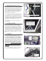
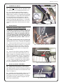
INSTALLATION & OWNER’S MANUAL
Rev. K, p. 1 of 11
POLARIS FREEDOM
CAB INSTALLATION INSTRUCTIONS
FOR THE POLARIS RANGER (p/n 2876196-067)
IMPORTANT: THIS ACCESSORY WEIGHS 340 POUNDS.
PLEASE ADJUST THE VEHICLE PAYLOAD ACCORDINGLY.
The contents of this manual are the property of the owner.
Be sure to leave with the owner when installation is complete.
Standard item with purchase of cab: one driver’s side wiper.
Optional accessories available: passenger’s side wiper, work lights, and strobe light.
Multiple U.S. and Foreign Patents Pending
Rev. K, p. 2 of 11
DESIGN CONCEPT
Curtis Cabs feature an assembly of parts designed for your vehicle which require adjustment
and alignment of components to accommodate vehicle variations and provide proper weather
protection. For accurate installation, proper operation, and years of satisfaction, please read
and understand the installation instructions.
From all of us at Curtis, we thank you for choosing our product.
GENERAL INFORMATION
Helpful Reminders:
A.
B.
C.
D.
Refer to parts diagram to help identify parts during assembly process.
Leave all bolts loose for later adjustment unless otherwise specified.
Read and understand all instructions before beginning.
Apply a clear silicone sealant to seal any minor gaps that may occur due
to vehicle variations.
Curtis Customer Service Hotline
1-800-343-7676 (ext. 1)
ADDED
WEIGHT
Curtis Cabs, blades and general accessories
add additional weight to the base vehicle. All
Curtis accessory weights are listed in product
brochures. Deduct the accessory's total weight
from the vehicle's rated capacity and never
exceed the vehicle's rated capacity including
driver and passenger.
Exposure to Carbon Monoxide can
Cause illness, serious injury or death.
Never operate vehicle if suspicious of
Carbon Monoxide. Inspect exhaust system for leaks monthly.
Leaks can result from loose connections, corrosion, cracks or
other damage to the exhaust manifold. If leaks are found, repair
or replace exhaust system. Do not use vehicle until repair or
replacement is complete.
DO NOT TRAVEL WITH WINDSHIELD IN FULL OPEN POSITION.
TOOLS REQUIRED:
1/4” & 3/8” DRIVE RATCHETS
3/8” DEEP SOCKET (3/8” DRIVE)
1/2” SOCKET (3/8” DRIVE)
10mm SOCKET (3/8” DRIVE)
5/32” AND 3/16” ALLEN WRENCHES
HAND DRILL
#2 PHILLIPS HEAD BIT TO USE IN DRILL
#2 and #3 PHILLIPS HEAD SCREWDRIVERS
T27 TORX BIT
BAR CLAMP
Rev. K, p. 3 of 11
WARNING!
Gasoline—Flammable! Explosive! Do not operate gasoline vehicle in an enclosed area without proper ventilation. The engine produces carbon monoxide, which is an odorless, deadly
poison.
This vehicle and enclosure will not provide protection from rollover, flying objects, lightening,
or other hazards. If caught in a storm, exit the vehicle and seek shelter in accordance with applicable safety guidelines for your location.
Only trained technicians should service or repair the enclosure. Anyone doing repairs or service should have knowledge and experience in electrical and mechanical repair. The appropriate instructions must be used when performing maintenance, service, or installation.
Follow the procedures exactly as stated in these instructions, and heed all DANGER, WARNING, and CAUTION statements both in this instruction manual as well as those posted on the
vehicle.
Prior to servicing the vehicle, turn the key switch to OFF and set the parking brake.
Always wear safety glasses or approved eye protection when servicing the vehicle.
Moving parts! Do not attempt to service the vehicle while it is running.
Hot! Do not attempt to service while engine, exhaust system, or motor are hot. Failure to heed
this warning could result in severe burns.
Use insulated tools when working near batteries or electrical connections. Avoid shorting components or wiring.
If wires are removed or installed, make sure wiring and wire harness are properly routed and
secured. Failure to properly route and secure wiring could result in vehicle malfunction, property damage, personal injury, or death.
Rev. K, p. 4 of 11
1.
VEHICLE PREP.
1.1 Using a T27 Torx bit, remove three (3) original
equipment screws on each side of the vehicle floorboard
as shown in fig. 1.1. Save these six (6) bolts for reinstallation in step 3.3. Note: these are self-tapping
screws that were factory installed. Use care when removing and re-installing to avoid cross-threading or damaging the female threads underneath the vehicle floorboard.
2.
“P” CLAMPS
2.1 Install a total of seven (7) “P” clamps as follows:
per fig. 2.1, place three (3) clamps on the rear tubular
frame oriented as shown. One in the center of the tubular
frame and one per side on the outer edges. Per fig. 2.1.1,
install two (2) clamps on each side tubular frame oriented
as shown. The front most clamp can be close to the front
welded joint and the rear most clamp can be 13” behind
the front one. Hardware will be installed in step 6.2.
3.
remove and save 3 bolts per side
before installing side frame
Fig. 1.1 View from passenger’s side
flat portion towards the sky
SIDE FRAME & DOOR ASS’Y.
3.1 With assistance, place the side frame assembly in
place on top of the vehicle floorboard per fig. 3.1. Attach
the middle front using the bracket shown, two 5/16-18 x
1” long hex head bolts, two internal tooth locking washers, and two flat steel washers into the factory installed
threaded inserts. See fig. 3.1.1. Hand tighten only.
place floorboard of side
frame onto floorboard of
vehicle lining up 3 holes
Ref.
Fig. 2.1 View from passenger’s side
flat portion towards the ground
Fig. 3.1 View from passenger’s side
Ref
Ref.
welded joint
Fig. 2.1.1 View from passenger’s side
front clamp
Fig. 3.1.1 View from driver’s side
Rev. K, p. 5 of 11
3.
SIDE FRAME & DOOR ASS’Y. (cont’d.)
3.2 Carefully open the door to the midway or slightly
beyond position to gain access for installing the hip restraint bracket. Insert the tongue of the bracket as shown
in fig. 3.2 and rotate the bracket up and install one 5/1618 x 1” long hex head bolt, one internal tooth locking
washer, and one flat steel washer into the factory installed weld nut. Leave bolt loose.
3.3 Re-install the three original equipment floorboard
screws through the bolt holes in the floorboard of the
side frame. See fig. 3.3. Reminder: these are self-tapping
screws that were factory installed. Use care to avoid
cross-threading or damaging the original female threads
underneath the vehicle floorboard. Leave bolts loose.
3.4 Repeat steps 3.1 through 3.3 for opposite side
frame assembly.
4.
WINDSHIELD SUPPORT
4.1 If installing optional work lights, pop the two
Heyco plugs out and discard them. If not installing optional work lights, leave the plugs in place. With assistance, install the windshield support as shown in fig. 4.1.
Install four 5/16-18 x 3/4” long hex head bolts, four internal tooth locking washers, and four flat steel washers.
Factory installed weld nuts are provided on the tabs of
the side frame. See right side of figure 4.1. Leave bolts
loose.
5.
WINDSHIELD
5.1 Have the following items ready: four 5/16-18 x
1 3/4” long flat head bolts, four steel washers, four 5/1618 locknuts, and two plastic spacer blocks. With assistance, place the windshield in place on the windshield
support with the 3/4” thick plastic spacer blocks underneath the plastic hinges for mounting up against the outer
surface of the windshield support per fig. 5.1. Adjust
windshield seal to the vehicle hood with side latches engaged and tighten. NOTE: hinges are plastic components. Do not overtighten. Torque to 7 ft.-lbs. max..
WARNING: do not travel with windshield in full
open position.
Ref.: hip restraint tube
Ref.
bent tab without hole slides into receiving slot
Fig. 3.2 View from passenger’s side
re-install 3 bolts per side
using care to avoid damaging female threads underneath vehicle floorboard
Fig. 3.3 View from passenger’s side
side
frame
mounting
holes
Fig. 4.1 View from driver’s side
5.2 Install the supplied nut covers (qty.: 4) on the locknuts inside the cab (front windshield hinge bolts).
3/4” thick
plastic spacer
Fig. 5.1 View from driver’s side
Rev. K, p. 6 of 11
6.
TIGHTEN ALL BOLTS
flat portion towards the ground
6.1 Tighten all cab bolts at this time. Reminder: do not
over-tighten the six (6) self-tapping floorboard screws.
6.2 Use a small bar clamp to hold the side frame
against the top side tubular frame. Using a drill and a
Phillips head bit, install two self-drilling and self-tapping
screws through the “P” clamps and into the underside of
the side frame tubing as shown in figure 6.2. Do not
over-torque these screws. Reminder: be sure these two
clamps are spread apart approximately 13”. One should
be just ahead of the ball stud and the other one as far forward as the tubular frame will allow before the welded
seam.
7.
Ref.
welded joint
Fig. 6.2 View from passenger’s side
REAR WINDOW
IMPORTANT INSTALLATION NOTICE!
To facilitate the rear panel installation to the cab, it is
recommended to lubricate the perimeter rubber seal
of the rear panel with a silicone or Armor All protectant/lubricant (or similar) non-flammable lubricant.
To prevent lubricant from contaminating the plastic
rear panel, spray lubricant onto a rag and in turn use
the rag to lubricate the perimeter rubber of the rear
panel.
This will allow the full seating of the rear panel in the
opening which is necessary for proper hole alignment.
7.1 Lift the bed. With assistance, place the rear window
in position. Fasten using four 1/4-20 x 1 1/4” long Truss
head, Phillips head bolts and four fender washers into
factory installed weld nuts on the rear tabs on the side
frames. Snug up the bolts. Do not over-compress the
rubber bushings.
7.2 Secure the vinyl filler by applying self-adhesive
backed velcro to the vehicle where needed. Note: selfadhesive backed velcro should be applied to a clean, dry
surface at room temperature. See fig. 7.2 for general locations. At location “a”, use a long piece along the bottom; at location “b”, use a small piece; and at location
“c”, use a long piece straight up to rear window. Repeat
“b” and “c” for opposite side. Attach the vinyl filler to
the newly installed hook velcro on the vehicle.
8.
a
c
b
Fig. 7.2 View of driver’s side lower rear corner
controls to be towards the front
Fig. 8.1 View from passenger’s side
ROOF & CONSOLE ASSEMBLY
8.1 Temporarily remove and save 2 fender washers
and 2 locknuts where indicated in fig. 8.6.1 on the next
page. With assistance, place the roof/console assembly in
place oriented so the controls are towards the front of the
vehicle. See figure 8.1.
8.2 If installing optional work lights, feed the two wires
through the hole in the windshield support where the
Heyco plugs were located. See figure 8.2. If not installing optional work lights, push the wiring back into the
holes of the overhead console.
Ref.: work light wires and
bracket mounting holes
Fig. 8.2 View from driver’s side
Rev. K, p. 7 of 11
8.
ROOF & CONSOLE ASS’Y. (cont.)
8.3 A driver’s side wiper is provided. Place the
driver’s side wiper wire below the front tubular frame as
shown in fig. 8.3. If installing an optional passenger’s
side wiper, place that wire below the front tubular frame
as well. If not installing a passenger’s side wiper, push
the passenger’s side wiring up into the console to hide it.
Caution: If installing a second wiper, double check that
both wipers have a maximum 85 degree sweep to avoid
interference. The motor should have a sticker on it indicating the degree of sweep.
8.4 If not installing optional work lights, install four
1/4-20 x 3/4” long Truss head, Phillips head bolts into
factory installed threaded inserts in the front of the overhead console. Leave bolts loose. Note: two per side
where the work light mounting bracket would be
mounted. See figure 8.2 on the previous page.
loomed wiper wires to be underneath the front tubular frame
Fig. 8.3 View from driver’s side
8.5 OPTIONAL: If installing the optional work lights
(kit p/n 2876382), discard the two brackets with the 3hole pattern on the light and use the supplied bracket
with the 4-hole pattern. See fig. 8.5. Install work light
brackets oriented as shown in figure 8.5.1. Use four 1/420 x 3/4” long Truss head, Phillips head bolts into factory installed threaded inserts in the front of the overhead
console. Leave bolts loose.
8.6 Install three 1/4-20 x 3/4” long Truss head, Phillips
head bolts through the three rear “P” clamps and into the
threaded inserts in the rear of the overhead console. See
fig. 8.6. Tighten the previously installed four bolts (2 per
side) holding the front of the overhead console to the
windshield support. Per fig. 8.6.1 below, re-install 2
fender washers and 2 locknuts (temporarily removed in
step 8.1) to secure the middle front of the roof/overhead
console assembly to the metal windshield support. Do
not overtighten.
discard the bracket
and carriage bolt
that is on the light
Fig. 8.5 Optional Work Light and Bracket
tabs with holes
should be pointing
towards the sky
8.7 OPTIONAL cont’d.: Attach the optional work
lights to the mounting brackets using the 1 7/8” long hex
head bolts that came on the set of work lights. Connect
the four wires (two per light) (male to female bullet connectors).
Fig. 8.5.1 Optional work light bracket
re-install fender washers and locknuts
and tighten so that the plastic of the
overhead console is snug against the
sheetmetal windshield support
Fig. 8.6.1 View from front of vehicle
factory installed
threaded insert
Fig. 8.6 View from passenger’s side
Rev. K, p. 8 of 11
this end towards the ground
9
GAS SHOCKS AND WIRING
9.1 Open the windshield and attach the two gas shocks
as shown in fig. 9.1 with the rod end of the gas shock
pointing down. Snap the gas shock onto the ball studs.
Leave the windshield in the open position.
9.2 Run the loomed battery wires over the front tubular frame, down along the side tubular frame and into the
gap behind the hood as shown in fig. 9.2. Secure the
loomed wire to the tubular frame using three of the supplied cable ties. Snip off excess length of cable tie if desired. Lift the hood of the vehicle. Using a 10mm socket
or Philips screwdriver, connect the long, red, positive
wire and the long, black, negative wire to the battery.
Wires are labeled. Connect the key-controlled wire as
follows: using a 3/8” deep socket, temporarily remove
the nut on the top threaded stud as shown in fig. 9.2.1.
Place the supplied ring terminal onto the stud and reinstall the original nut and tighten. Ref.: the top stud
should already have an orange wire with a white stripe.
This is the vehicle’s key-controlled wire.
9.3 Note: there are two (2) extra wires with female
bullet connectors that are only used if a heater is being
installed. The blue wire is for the low speed and the gray
wire is for the high speed. When finished with the wire
connections, coil up the extra length of loomed wire and
use a cable tie to secure the wires in place as desired.
10.
Fig. 9.1 Gas shock for windshield
run loomed wire
into this gap
Fig. 9.2 View from driver’s side
FINISHING TOUCHES
10.1 Make sure the rubber flaps are appropriately sealing against the sides of the plastic hood of the vehicle.
See figure 10.1.
10.2 Using a 5/32” Allen wrench, set the antenna at a
desired angle and re-tighten the set screw.
10.3 Install wiper per instructions included in the wiper
kit. One wiper is included with the cab. A second wiper
is available as an additional option. Caution: If installing a second wiper, double check that both wipers have a
maximum 85 degree sweep to avoid interference. The
motor should have a sticker on it indicating the degree of
sweep.
10.4 Note: extra hardware has been provided in case
they get lost. Discard extras such as washers, locknuts,
“P” clamps, cable ties, etc.
It is recommended that
with a cab installed, the
vehicle should be trailered facing backwards.
attach to the top threaded stud that
has the orange wire with white stripe
Fig. 9.2.1 View from driver’s side
rubber flap
Fig. 10.1 View from driver’s side
Rev. K, p. 9 of 11
CARE AND MAINTENANCE (IMPORTANT: be sure to leave this page with
the owner once installation is complete.
Check and tighten hardware after 40 hours of operation.
Periodically inspect and tighten hardware for the remainder of the unit’s service life.
IMPORTANT CLEANING INFORMATION
Keep the enclosure components clean in order to prevent dust and dirt from forming an unattractive film. The life
of your acrylic windows, doors, and body panels depends upon following these care procedures:
REAR ACRYLIC WINDOW:
1) NEVER USE AN ALCOHOL-BASED PRODUCT FOR CLEANING. Do not use WINDEX, GLASS PLUS,
FANTASTIC, etc. Use of these products will result in deterioration of the acrylic item.
2) Wash with a mild soap or detergent using your bare hands to free or dislodge any caked-on dirt or other foreign particles.
3) A soft, grit-free cloth, sponge, or chamois may be used but only as a means of carrying water to the windows.
4) The interior should be lightly dusted (NOT WIPED) with a clean soft cloth or chamois. The cloth or chamois
should be kept free of grit by frequent rinsing in clean water.
5) Grease and oil may be removed with kerosene.
6) Novus I and Novus II are recommended plastic cleaners for acrylic units and can be used to remove light
scratches.
GLASS WINDOWS:
1) Windex and other glass cleaners can be used on glass windows.
DOORS AND BODY PANELS:
1) NEVER USE AN ABRASIVE DETERGENT/VEHICLE CLEANER OR A WIRE BRISTLED BRUSH.
Do not use any CITRUS BASED CLEANERS such as orange or lemon. Use of these products will cause the
plastic to become permanently damaged.
2) Clean the plastic enclosure surfaces thoroughly with warm soapy water and a COTTON cloth or chamois. Be
sure to use mild soap, specifically a dish liquid or equivalent. Clean in a light circular motion for best results.
3) Use EXTRA CAUTION when cleaning the interior of the enclosure. The interior is more sensitive than the
exterior because the exterior has an extra coating for U.V. stability.
4) Remove grease and oil with mineral spirits and a COTTON cloth or chamois.
WARNING: do not travel with
windshield in full open position.
It is recommended that with a cab installed, the
vehicle should be trailered facing backwards.
Curtis Customer Service Hotline: 1-800-343-7676 (ext. 1)