1
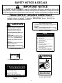
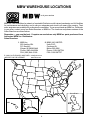
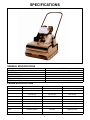
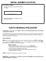
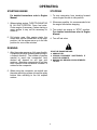
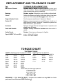
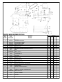
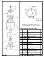
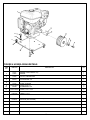
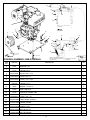
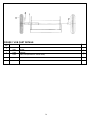
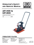
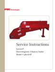
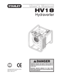
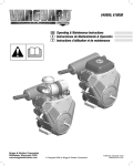
GP7000
parts
and
service
manual
It is the OWNER'S RESPONSIBILITY to communicate information on
the SAFE USE and OPERATION of this machine to the operators !
MBW INC.
P.O BOX 440 250 HARTFORD ROAD
SLINGER, WI 53086-0440
PHONE: (262) 644-5234 FAX (262) 644-5169
MBW CORPORATE INTERNET ADDRESS
EĆMAIL: [email protected]
L1315 / 01.05 D
MBW Inc 2005
Printed in U.S.A.
WEB SITE: www.mbw.com
IN ENGLAND:
MBW (UK) LIMITED
Units 2 & 3
Cochrane Street
Bolton BL3 6BN
Phone: 01204 387784 FAX: 01204 387797
TABLE OF CONTENTS
SAFETY PRECAUTIONS . . . . . . . . . . . . . . . . . . . . . . . . . . . . . . . . .
1
SAFETY DECALS & LOCATIONS . . . . . . . . . . . . . . . . . . . . . . . . . .
2
WARRANTY . . . . . . . . . . . . . . . . . . . . . . . . . . . . . . . . . . . . . . . . . . . .
3
MBW WAREHOUSE LOCATIONS . . . . . . . . . . . . . . . . . . . . . . . . .
4
SPECIFICATIONS . . . . . . . . . . . . . . . . . . . . . . . . . . . . . . . . . . . . . . .
5
SERIAL NUMBER LOCATION . . . . . . . . . . . . . . . . . . . . . . . . . . . . .
6
PARTS ORDERING PROCEDURE . . . . . . . . . . . . . . . . . . . . . . . . .
6
OPERATION INSTRUCTIONS . . . . . . . . . . . . . . . . . . . . . . . . . . . . .
Introduction
Before Operation
Operating
PERIODIC MAINTENANCE . . . . . . . . . . . . . . . . . . . . . . . . . . . . . . .
Engine Maintenance
Ground Pounder Maintenance
REPLACEMENT AND TOLERANCE CHART . . . . . . . . . . . . . . . .
7
10
TORQUE CHART . . . . . . . . . . . . . . . . . . . . . . . . . . . . . . . . . . . . . . . .
10
MAIN ASSEMBLY (Figure 1) . . . . . . . . . . . . . . . . . . . . . . . . . . . . . .
11
EXCITER ASSEMBLY (Figure 2) . . . . . . . . . . . . . . . . . . . . . . . . . .
12
EXCITER OIL LEVEL CHECK (Figure 3) . . . . . . . . . . . . . . . . . . .
12
HONDA ENGINE ASSEMBLY (Figure 4) . . . . . . . . . . . . . . . . . . . .
13
YANMAR ENGINE ASSEMBLY (Figure 5) . . . . . . . . . . . . . . . . . . .
Throttle Assembly Details
KOHLER ENGINE ASSEMBLY (Figure 6) . . . . . . . . . . . . . . . . . . .
14
JOB CART DETAILS (Figure 7) . . . . . . . . . . . . . . . . . . . . . . . . . . . .
16
i
9
15
SAFETY PRECAUTIONS
BEFORE YOU ATTEMPT TO OPERATE THIS EQUIPMENT, READ AND
STUDY THE FOLLOWING SAFETY INFORMATION. IN ADDITION, MAKE
SURE THAT EVERY INDIVIDUAL WHO OPERATES OR WORKS WITH
THIS EQUIPMENT IS FAMILIAR WITH THESE SAFETY PRECAUTIONS.
WARNING - LETHAL EXHAUST GAS!
An internal combustion engine discharges carbon monoxide, a poisonous, odorless and
invisible gas when operating. Death or serious illness may be caused if inhaled. Operate
only where deadly exhaust gases can be safely dissipated, NEVER IN A CONFINED
AREA!
WARNING - DANGEROUS FUELS!
Use extreme caution when storing, handling and using fuels - they are highly volatile and
explosive in vapor state. Do not add fuel while engine is running. Stop engine and, if possiĆ
ble, allow cooling period to prevent spilled fuel from igniting on contact with hot engine
parts. DO NOT SMOKE!
SAFETY GUARDS
It is the responsibility of the owner to ensure that ALL GUARDS AND SHIELDS remain in
place.
IGNITION SYSTEMS
Breakerless, magneto and battery ignition systems CAN CAUSE SEVERE ELECTRICAL
SHOCKS. Avoid contacting these units or their wiring.
SAFE DRESS
DO NOT WEAR loose clothing, neckties, rings, wristwatches, bracelets, etc., when around
machinery.
NOISE PROTECTION
Wear O.S.H.A. specified hearing protection devices.
FOOT PROTECTION
Wear O.S.H.A. specified steel tip safety shoes.
HEAD PROTECTION
Wear O.S.H.A. specified safety helmets.
EYE PROTECTION
Wear O.S.H.A. specified eye shields, safety glasses, and sweat bands.
OPERATOR
Keep children and bystanders off and away from the equipment.
REFERENCES
For details on safety rules and regulations in the United States, contact your local OccupaĆ
tional Safety and Health Administration(O.S.H.A.) office.
Equipment operated in other countries must be operated and serviced in accordance and
compliance with any and all safety requirements of that country.
The publication of these safety precautions is done for your information. MĆBĆW Inc. does
not by the publication of these precautions, imply or in any way represent that these are the
sum of all dangers present near MĆBĆW Equipment. If you are operating MĆBĆW Inc. equipĆ
ment, it is your responsibility to insure that such operation is in full accordance with all apĆ
plicable safety requirements and codes. All requirements of the United States Federal OcĆ
cupational Safety and Healthy Administration Act must be met when operated in areas that
are under the jurisdiction of that United States Department.
1
SAFETY NOTICE & DECALS
IMPORTANT NOTICE
The SAFETY ALERT SYMBOL" is used to call attention to items or operations that may be
dangerous to machine operators or others working with this equipment. The symbol can be
found throughout this manual and on the unit itself. Please read these messages carefully.
READ SAFETY DECALS CAREFULLY
Carefully read and follow all safety decals. Keep them in good condition. If decals become
damaged, replace as required. If repainting, REPLACE ALL decals. Decal Kits are
available from authorized MBW Distributors.
AIR CLEANER INSTRUCTIONS
CAUTION
CLEAN ELEMENT DAILY. MORE OFTEN UNDER DUSTY CONDITIONS.
TAP ELEMENT LIGHTLY ON A FLAT SURFACE - IF DUST DOES NOT
DROP OFF EASILY OR IF ELEMENT IS BENT OR CRUSHED...................
REPLACE IT!
WARNING: DO NOT OPERATE ENGINE WITHOUT AIR CLEANER
ELEMENT - INTERNAL DAMAGE WILL RESULT!
Read the Operating Instructions before
operating this piece of equipment.
Keep unauthorized and untrained
people away from this equipment.
ROTATING & MOVING PARTS! Make
sure all guards and safety devices are in
place.
DO NOT RUN this machine in an enĆ
closed area. The engine produces carĆ
bon monoxide, a POISONOUS GAS.
06079
#06079, ON ENGINE
PLATES
OPERATING INSTRUCTIONS
1. Check engine oil.
2. Open fuel valve.
3. Choke engine. A warm engine may not
need to be choked.
4. Open throttle part way.
5. Pull starter rope.
6. After starting: open choke, return
throttle to idle position.
7. During operation, when excessive kickĆ
back is noticed, maximum compaction
has been reached.
8. To stop: Return throttle to idle position,
press Stop" button, close fuel valve.
Wear approved hearing protection, foot
protection, eye protection and head
protection.
SHUT OFF the engine before servicing,
cleaning or adding fuel.
Failure to comply could result in seriĆ
ous bodily injury.
13483
#13483, BELTGUARD
13482
#13482, BELTGUARD / DECK
WARNING
01069
RUN
THROTTLE
#01069, THROTTLE LEVER
WARNING
When lifting attach proper safety
chains to this hook.
Approximate weight
GP7000: 655 lbs. (300 kg)
13479
ROTATING PARTS
Keep hands away!
13484
#13479, ON DECK, IN FRONT OF
HOOK
#13484, BELTGUARD
2
WARRANTY
WARRANTY
THIS IS YOUR WARRANTY - PLEASE READ AND SAVE
1. MBW Inc., Slinger Wisconsin, warrants each new machine against defects in material and workmanship
under normal use and service for a period of six (6) months. This warranty commences the first day the
machine is sold, assigned to a rental fleet, or otherwise put to first use.
2. The obligation under this warranty is limited to the replacement or repair of parts and/or machine at MBW
Inc. factory branches or at authorized MBW Inc. Distributors.
3. Machines altered or modified without MBW Inc. written consent voids this warranty. Misuse, negligence,
accidents or the operation of machines in any way other than recommended by MBW Inc. will void this
warranty. This warranty shall not apply to machines repaired by other than MBW Inc. factory branches or
authorized MBW Inc. Distributors.
4. This warranty includes labor on all MBW Inc. products. Labor must be performed at an authorized MBW
Inc. Distributor.
5. The cost of transportation and other expenses connected therewith are not covered by this warranty.
6. Written authorization for the return of merchandise under warranty must be obtained from MBW Inc.,
Slinger, Wisconsin. In England: MBW (UK) LIMITED, Units 2 & 3, Cochrane Street, Bolton BL3 6BN.
7. MBW Inc. reserves the right to inspect and render final decision on each warranty case.
8. MBW Inc. reserves the right to improve or make product changes without incurring any obligation to
update, refit, or install the same on machines previously sold.
9. MBW Inc. is not responsible for any liability or damage or injury directly or indirectly from design, material or
operation of its products.
10. Warranty card must be returned to MBW Inc., P.O. Box 440, Slinger, Wisconsin 53086-0440, within 10 days
after purchase, assignment to a rental fleet, or first use. In England: MBW (UK) LIMITED, Units 2 & 3,
Cochrane Street, Bolton BL3 6BN. Failure to return warranty card as specified renders the warranty null and
void.
11. Requests for warranty must be submitted in writing within 30 days after machine failure to MBW Inc., P.O.
Box 440, Slinger, Wisconsin 53086-0440. In England: MBW (UK) LIMITED, Units 2 & 3, Cochrane Street,
Bolton BL3 6BN.
12. THE FOREGOING WARRANTY IS EXPRESSLY IN LIEU OF ALL OTHER WARRANTIES, EXPRESSED OR
IMPLIED, INCLUDING THE WARRANTIES OF MERCHANTABILITY AND FITNESS FOR USE, AND OF ALL
OTHER OBLIGATION OR LIABILITIES ON OUR PART, AND WE NEITHER ASSUME NOR AUTHORIZE ANY
OTHER PERSON TO ASSUME FOR US ANY OTHER LIABILITY OR WARRANTY IN CONNECTION WITH
THE SALE OR SERVICE OF ANY OF OUR PRODUCTS. LIKEWISE, THIS WARRANTY SHALL NOT APPLY
WITH RESPECT TO ENGINES, MOTORS AND OTHER COMPONENT PARTS PRODUCED BY OTHER
MANUFACTURERS AND USED ON MBW PRODUCTS, BUT SUCH ITEMS SHALL HAVE SUCH
WARRANTIES AS MAY BE PROVIDED BY THE MANUFACTURER THEREOF.
MBW INC.
250 HARTFORD ROAD P.O. BOX 440
SLINGER, WI 53086-0440
PHONE: (262) 644-5234 FAX (262) 644-5169
MBW CORPORATE INTERNET ADDRESS
E-MAIL: [email protected]
IN ENGLAND:
MBW (UK) LIMITED
Units 2 & 3
Cochrane Street
Bolton BL3 6BN
Phone: 01204 387784 FAX: 01204 387797
3
WEB SITE: www.mbw.com
MBW WAREHOUSE LOCATIONS
is at your service
MBW Inc. has established a network of reputable Distributors with trained mechanics and full facilities
for maintenance and rebuilding, and to carry an adequate parts stock in all areas of the country. Their
sales engineers are available for professional consultation. If you cannot locate an MBW Inc. Distributor
in your area, contact one of our Sales Branches or MBW Inc. The locations and phone numbers of the
Sales Branches are listed below.
Remember - you own the best. If repairs are needed use only MBW Inc. parts purchased from
Authorized MBW Inc. Distributors.
Sales Branches:
1. MBW Inc.
250 Hartford Rd.
P.O. Box 440
Slinger, WI 53086Ć0440
Phone: (262) 644Ć5234
FAX: (262) 644-5169
2. MBW (UK) LIMITED
Units 2 & 3
Cochrane St.
Bolton BL3 6BN
Phone: 01204 387784
FAX: 01204 387797
E-MAIL ON THE WORLD WIDE WEB [email protected]
WEB SITE ON THE INTERNET
www.mbw.com
1
Great Britain
2
4
SPECIFICATIONS
GENERAL SPECIFICATIONS
GP7000
7900lbs (3585 kg)
2800
100 ft/min (30 m/min)
30 in (76 cm)
26 x 30 in (66 x 76 cm)
653 lbs (296 kg)
CENTRIFUGAL FORCE*
EXCITER VPM
TRAVEL SPEED
COMPATION DEPTH
WIDTH AND LENGTH
OPERATING WEIGHT (HONDA)
ENGINE SPECIFICATIONS
Honda GX340
Yanmar L100AEĆD
Kohler K301T
07767
11929
00802
DISPLACEMENT
20.6 cu in. (337 cc)
24.78 cu in. (406 cc)
39.07 cu. in. (467 cc)
BORE & STROKE
3.23 x 2.5 in
(72 x 64 mm)
3.39 x 2.76 in.
(86 x 70 mm)
3.38 x 3.25 in
(86 x 83 mm)
POWER RATING
11 hp (8.2 kw)
10 hp (7.4 kw)
12 hp (9 kw)
Champion RN9YC or eq.
-
Champion RHĆ10 or equ.
DRY WEIGHT
68 lbs (31 kg)
106 lbs (48 kg)
123 lbs (56 kg)
AIR CLEANER
Dry element type
Wet element
Dry element type
STARTER
Retractable rewind
Retractable rewind
Retractable rewind
FUEL
Unleaded gasoline
#2 Diesel
Unleaded or
Regular gasoline
1.7 gal (6.5 ltr)
1.45 gal (5.5 ltr)
1.5 gal (5.7 ltr)
MBW Part No.
SPARK PLUG
FUEL TANK CAPACITY
*Output specifications in compliance with LEMB standards (Light Equipment Manufacturers Bureau of CIMA).
5
SERIAL NUMBER LOCATION
PLATE SERIAL NUMBER
1. Located on the top of the engine deck, behind
the engine.
(Write Serial Number in box.)
2. The serial number is also stamped on top of
the exciter housing.
PARTS ORDERING PROCEDURE
The Warranty is stated in this book on page 3. Failure to return Warranty Registration Card renders
the Warranty null and void.
An Operating Instructions and Parts Catalog for the engine is also furnished. Engine Parts may be orĆ
dered from any authorized dealer. Refer to the Engine Operating Instructions and Parts Catalog for exĆ
ploded view and parts identifications.
PARTS ORDERING
MBW Inc. parts are available worldwide and must be ordered through your local MBW Inc. Distributor.
If you cannot locate an MBW Inc. Distributor in your area, refer to page 4 of this Manual, locate the MBW
Inc. Sales Branch nearest you and call for assistance.
ALWAYS INCLUDE:
1. Model and Serial Number of Machine when ordering MBW Parts.
2. Engine Model and Serial Number when ordering Engine Components.
3. Item Part Number, Description and Quantity.
4. Company Name, Address, Zip Code, and Purchase Order Number.
5. Preferred method of shipping.
MBW Inc. ships parts the same day as orders are received.
REMEMBER - you own the best. If repairs are needed use only MBW Inc. parts purchased from
Authorized MBW Inc. Distributors.
6
OPERATING INSTRUCTIONS
INTRODUCTION
MBW Inc. Compaction Equipment is intended for use in very severe applications. They are
powered by four stroke engines and are available in different sizes and a selection of engines.
This parts manual contains only standard or standard option parts. Variations of these parts as
well as other special parts are not included. Contact your local MBW Inc. Distributor for assistance
in identifying parts not included in this manual.
BEFORE OPERATION
After receiving your new MBW Inc. Ground Pounder® Compactor, inspect it for any visible damage
done during shipment. Make sure the engine throttle works properly (see engine owner's
manual). Contact your nearest MBW Inc. Distributor if there are any problems.
REMEMBER! It is the owner's responsibility for communicating information on the
safe use and proper operation of this unit to the operators.
Make sure hands, feet, and clothing are at a safe distance from any moveable parts
prior to starting.
Before operating, review related SAFETY PRECAUTIONS listed on page 1 of this
manual.
Familiarize yourself with the operation of the equipment BEFORE starting the engine.
Know how to STOP the equipment.
OIL LEVEL- Check the oil level in the engine. For more information see Lubrication"
under the respective engine's Owners Manual" or the PERIODIC MAINTENANCE
section of this manual.
AIR CLEANER- Check to ensure element is in good condition and properly installed.
FUEL SUPPLY- The engines on MBW Inc. Compaction equipment require an
automotive grade of clean, fresh, unleaded or regular gasoline.
FUEL FILTER-If clogged or damaged, replace.
7
OPERATING
STARTING ENGINE
STOPPING
For detailed instructions refer to Engine
Manual.
1. To stop compactor from traveling forward
return engine throttle to idle position.
1. When starting engine, THROTTLE MUST BE
IN AN IDLE POSITION. Open fuel valve.
Choke engine if necessary, (when starting a
warm engine it may not be necessary to
choke it).
2. Whenever possible, it is recommended to let
the engine idle before stopping.
2. Pull starter rope. After engine starts, the
choke lever can be moved back to the open
position. Let the engine warm up in the idle
position for one or two minutes.
3. Turn switch on engine to STOP' position.
For detailed instructions refer to Engine
Manual.
4. Turn off fuel valve.
RUNNING
STOP THE ENGINE BEFORE:
1. After the engine warms up, fully open throttle.
Compactor will begin vibrating and moving in
a forward direction. The number of passes
needed to reach the compaction level
desired will depend on soil type and
moisture. Maximum compaction of soil has
been reached when excessive kickback is
noticed in the compactor.
ADDING FUEL.
LEAVING EQUIPMENT UNATTENDED, IF
ONLY FOR A MINUTE.
MAKING ANY REPAIRS OR ADJUSTMENTS
TO UNIT.
2. When using the compactor on asphalt use
the water sprinkling system to keep the plate
bottom from adhering to the hot asphalt
surface.
8
PERIODIC MAINTENANCE
ENGINE MAINTENANCE
AIR CLEANER
1.
Your Compactor uses either a dry type air cleaner element or a
Dual" Oil-Foam and Paper Element. Clean the dry element or
Oil-Foam" element every 25 hours under normal conditions
and every few hours under extremely dusty conditions.
a.
CAUTION!
Oil in exciter is HOT after machine has been running!
Where protective gloves when working with oil.
Clean the dry element by tapping it lightly on a flat surface.
Keep tapping until no dust comes off. The element should
be replaced if the dust does not drop off easily or if the eleĆ
ment becomes bent or crushed.
Note: Do not wash elements in any liquid of blow dirt off
with air. Do not tap element on a sharp corner, it may damĆ
age the seal.
b.
Clean the Oil Foam" type element by washing it in keroĆ
sene or liquid detergent and water to remove the dirt. Wrap
the foam in a cloth and squeeze dry. Saturate the foam in
engine oil and squeeze it to remove excess oil. Assemble
the parts and reinstall air cleaner to engine.
a.
Let engine cool before changing exciter oil.
b.
Remove belt guard and belt.
c.
Remove the 1/2" hex head cap screws from sided of plate
housing.
d.
Lift entire housing deck with engine from plate housing.
e.
Remove the 3/8" drain screw (Figure 2, item 20) from the exĆ
iter housing cover.
f.
Tilt plate housing upside down so oil drains from exciter
housing. (Examine oil for metal chips as a precaution to fuĆ
ture troubles.)
g.
Replace drain screw
h.
Tip plate housing upright and remove the 3/8" plug pipe on
top of the exciter. Fill using 24 oz. (720ml) of MBW Ground
Pounder® Exciter Oil (Oil can be purchased from your loĆ
cal MBW Distributor, part #01058). Replace the pipe plug!
i.
Install housing deck, belt and belt guard.
SPARK PLUG
A dirty, oily or carboned spark plug makes starting difficult and causes
inefficient operation. Remove and clean spark plug as necessary (see
engine manual). Set spark plug gap as described in engine manual.
LUBRICATION
Clean dirt from around oil fill cap and check oil level. Oil level should
be between the FULL" and ADD" marks on the dipstick or to overflow
point in fill hole on engine without dipstick.
3.
Change oil after first two (2) hours of operation, and after every
twenty-five (25) hours thereafter or at the end of each season. To
change oil, tilt machine back and place a pan to catch oil underneath
engine deck. Remove drain plug from engine and let oil drain into
pan.
a.
4.
1.
ENGINE RPM
The idle speed of the engine must not exceed 1800 rpm. If the
idle speed is greater the clutch may not disengage. Check enĆ
gine owner's manual for procedure on setting idle speed.
GROUND POUNDER®
MAINTENANCE
GENERAL MAINTENANCE
1.
2.
On a new Ground Pounder®, the exciter is pre-oiled at the factoĆ
ry, and needs no immediate attention.
a.
Replace exciter oil once every season or every 500 hours.
b.
The oil capacity of the exciter is 24 oz. (720ml)
c.
Use only MBW Ground Pounder® Exciter Oil available in
6 packs (#01058).
Engine Removal.
There are two methods of engine removal.
Replace engine drain plug and wipe oil off engine deck. Refill engine
with oil in accordance to recommendations found in engine manual.
2.
When belt stretch develops, loosen (do not remove) 4 enĆ
gine mounting screws, pull engine back. Retighten engine
bolts.
DISASSEMBLY PROCEDURE
If engine has been running, oil will be HOT! Where proĆ
tective gloves when working with engine oil.
The engine should be set at an operating speed of 3400 rpm.
Check engine owner's manual for procedure on setting operatĆ
ing speed.
Remove excess soil which enters rear of plate.
Belt Adjustment
a.
CAUTION!
1.
Keep Plate Clean
a.
To work on engine only, remove the belt guard, belt and 4
engine mounting screws.
b.
The second method is to remove the entire engine deck
(See b, c and d of exciter oil change)
2.
For Engine repair, see your Authorized Engine Dealer.
3.
Exciter Disassembly (Use Figure 2, Page 12)
a.
Remove engine deck per steps b, c and d under Exciter Oil
Change.
b.
Remove 4 exciter holdĆdown bolts and clean exciter before
proceeding with disassembly.
c.
Remove VĆpulley. If pulley is froze, go to the next step.
d.
Remove rear cover (item 3) by unscrewing the 6 flange
screws.
e
Block the exciter housing on large O.D. side, then press exĆ
citer shaft through housing.
f.
Remove front cover.
Note:
Exciter Oil Change Procedure.
9
Always replace oil seal (item 2) after any teardown.
g.
To remove the roller bearing in the rear cover, remove snap
ring (Item 5), then remove the two inner hex head cap
screws. Use two 1/4" dia pins 2" long placed in the 5/16"
threadded holes. Use square stock over the pind to bridge
and press out the bearing.
h.
When reassembling use new gaskets, items 23 & 24 or
FormĆAĆGasket" type compound.
REPLACEMENT AND TOLERANCE CHART
Part
TOLERANCE OR REPLACEMENT CYCLE
Air Cleaner Element
Replace after 75 hours if Engine is operating under good
clean air conditions. Service and replace more frequently if
under extreme dusty or dirty conditions.
Bearings
Replace anytime a Bearing is rough, binding or discolored.
Clutch
Replace the Shoes and Spring if they show signs of heat damĆ
age or the Clutch does not disengage below 2000 rpm.
Engine Breaker Points
See the engine manufacturer's Operator's Manual.
Exciter Oil
Replace once every season or every 500 hours. Use 8 oz. of
MBW Ground Pounder ® exciter oil. Available in 6 packs from
MBW Distributors, part #01058.
Hardware
Retorque all bolts after the first eight hours of operation and
check every 25 hours.
Seals and Gaskets
Replace at every overhaul or teardown and when exciter is
rebuilt.
Safety Decals
Replace if they become damaged or illegible.
Special MBW Tools and Kits
#01607 DECAL SET, GP7000
#01629 TEST MAT, RUBBER
TORQUE CHART
TIGHTENING TORQUE
GENERAL (Tightening Torque into Cast Iron or Steel)
Tightening Torque into Aluminum
SIZE
10Ć24
10Ć32
1/4Ć20
1/4Ć28
5/16Ć18
5/16Ć24
3/8Ć16
3/8Ć24
7/16Ć14
7/16Ć20
1/2Ć13
1/2Ć20
SIZE
10Ć24
1/4Ć20
5/16Ć18
3/8Ć16
7/16Ć14
1/2Ć13
GRADE 2
32 in lb
32 in lb
70 in lb
85 in lb
150 in lb
165 in lb
260 in lb
300 in lb
35 ft lb
45 ft lb
50 ft lb
70 ft lb
GRADE5
40 in lb
32 in lb
115 in lb
140 in lb
250 in lb
270 in lb
35 ft lb
40 ft lb
55 ft lb
75 ft lb
80 ft lb
105 ft lb
GRADE 2
32 in lb
70 in lb
150 in lb
260 in lb
35 ft lb
50 ft lb
GRADE 5
32 in lb
70 in lb
150 in lb
260 in lb
35 ft lb
50 ft lb
Exciter bolts (item #6&7 page 9)300 ft lb
CONVERSIONS
in lbs x 0.083 = ft lbs
ft lbs x 12 = in lbs
ft lbs x 0.1383 = kgm
ft lbs x 1.3558 = Nm
REMEMBER - YOU OWN THE BEST! If repairs are needed use only MBW Inc. Parts
purchased from Authorized MBW Distributors.
10
FIGUREā1 MAIN ASSEMBLY DETAILS
00716
00744ĆLA
00744ĆLB
00744ćRA
00744ĆRB
F081318HCS
F08LW
F0813HN
05940
05939
F12LW
00813
00746
F042008HCS
F05SW
F04LW
F0420HN
00048
F0518FN
F0820HN
07661
F06LW
F0616HN
F061612HCS
F081310HCS
07795
07798
07799
00766
07797
F061614HCS
06333
00749
F061606HCS
00730
00763
00732
07014
F0212CP
3
4
5
6
7
8
9
10
11
12
13
14
15
16
17
18
19
20
21
22
23
24
25
26
27
28
29
30
31
32
33
34
HOUSING
MOLD BAR, LEFT FRONT
MOLD BAR, LEFT REAR
MOLD BAR, RIGHT FRONT
MOLD BAR, RIGHT REAR
HHCS, 1/2Ć13 x 2Ć1/4
LOCKWASHER, 1/2
HEX NUT, 1/2Ć13
HEX HEAD CAP SCREW (TORQUE TO 300 ft lbs)
HEX HEAD CAP SCREW (TORQUE TO 300 ft lbs)
LOCKWASHER, 3/4
DECK
APRON
HHCS, 1/4Ć20 x 1
PLAINWASHER, 5/16
LOCKWASHER, 1/4
HEX NUT, 1/4Ć20
HOOK BOLT
FLANGE NUT, 5/16Ć18
HEX NUT, 1/2Ć20
SHOCKMOUNT
LOCKWASHER, 3/8
HEX NUT, 3/8Ć16
HHCS, 3/8Ć16 x 1Ć1/2
HHCS, 3/8Ć13 x 1Ć1/4
SPACER, TIEROD (#00811 KOHLER ONLY)
MOUNTING BAR
MOUNTING BAR
MOUNTING BAR
SPACER (#00812 KOHLER ONLY)
HHCS, 3/8Ć16 x 1Ć3/4
VĆBELT, BĆ47 (#07030 B-49 YANMAR ONLY)
DAMPENER
HHCS, 3/8Ć16 x 3/4
BELTGUARD
BRACKET ASSEMBLY
HANDLE ASSEMBLY
BUSHING
COTTER PIN, 1/8 x 1Ć1/2
11
GP7000
K301T
1
2
DESCRIPTION
Bezeichnung
Designation
Descripcion
L100E
PART NO.
TeileĆNr.
No. de la piece
No. de la parte
GX340
ITEM NO.
BildĆNr.
No. repere
No. item
1
1
1
1
1
12
29
14
2
2
4
1
1
4
4
4
4
2
4
12
6
10
2
4
12
1
1
1
1
1
1
1
1
12
29
14
2
2
4
1
1
4
4
4
4
2
4
12
6
10
1
1
1
1
1
12
29
14
2
2
4
1
1
4
4
4
4
2
4
12
6
10
3
4
12
1
1
1
4
2
1
2
1
2
1
2
2
2
1
2
1
2
1
2
2
4
12
1
1
1
2
1
4
2
1
2
1
2
1
2
2
NOTE: Use only MĆBĆW Ground Pounder
Oil purchased in six packs, Part No. 01058
FIGURE 3 EXITER OIL LEVEL CHECK
ITEM NO.
PART NO.
DESCRIPTION
QTY.
FIGURE 2
1
2
3
4
5
6
7
8
9
10
11
12
13
14
15
16
00703
07009
00704
07010
07011
F0205SP
01072
00702
07012
00701
07013
F06LW
F061610HCS
F061608SCS
00706
00705
COVER,FRONT
SEAL
COVER,REAR
BEARING,CYL ROLLER
RETAINING RING, INTERNAL
SPIROL PIN, 1/8 x 5/8
FILTER
SHAFT
RETAINING RING,EXTERNAL
HOUSING
BEARING, SPHERICAL ROLLER
LOCKWASHER, 3/8
HHCS, 3/8Ć16 x 1Ć1/4
SHCS, 3/8Ć16 x 1
KEY
VĆPULLEY
17
18
19
20
21
22
00707
F08LW
F081314HCS
F061606HCS
F0227SPP
F0618SPP
STEP WASHER
LOCKWASHER, 1/2
HHCS, 1/2Ć13 x 1Ć3/4
HHCS, 3/8Ć16 x 3/4
SOCKET PIPE PLUG, 1/8Ć27
SOCKET PIPE PLUG, 3/8Ć18
1
1
1
2
1
1
23
00710
0710R
EXCITER ASM, (INLCUDE ALL ABOVE ITEMS)
EXCITER ASM, (REBUILT)
1
1
12
1
1
1
1
1
1
1
1
1
1
1
12
6
6
1
1
12
13
11
10
FIGURE 4 HONDA GX340 DETAILS
ITEM
NO.
PART NO.
1
2
3
4
5
6
7
8
07767
07802
17125
07008
16381
F06LW
F062412HCS
07794
ENGINE, HONDA GX340 11hp
SPACER
KEY
CLUTCH, CENTRIFUGAL
PLAINWASHER
LOCKWASHER, 3/8
HHCS, 3/8Ć24 x 1Ć1/2
PLATE, ADAPTER
1
1
1
1
1
1
1
1
9
10
11
12
13
F061616HCS
F06SW
F0616FN
F081314HCS
F08LW
F0813HN
HHCS, 3/8Ć16 x 2
PLAINWASHER, 3/8
FLANGE WHIZĆLOCK NUT, 3/8Ć16
HHCS, 1/2Ć13 x 1Ć3/4
LOCKWASHER, 1/2
HEXNUT 1/2Ć13
4
4
4
2
4
2
EXTENSION, MUFFLER (NOT SHOWN)
MUFFLER (NOT SHOWN)
1
1
12614
K275679
DESCRIPTION
13
QTY.
17
20
18
13
14
21
15
1
3
5
PTO SIDE
10
2
11
16
9
30
23
32
25
29
26
31
28
24
7
27
4
8
6
SPRING ATTACHES AS SHOWN,
USE THE THIRD HOLES FROM
CENTER PIVOT.
FIGURE 6 YANMAR L100EĆD DETAILS
ITEM
NO.
1
2
3
4
5
6
7
8
PART NO.
DESCRIPTION
19
GOVERNOR ATTACHED
TO ENGINE
QTY.
ENGINE, YANMAR L100AEĆD
BUSHING, PTO
KEY
WASHER, PILOT
CLUTCH, CINTRIFUGAL
SHCS 7/16Ć20 x 1Ć1/4
PLATE, ADAPTER
HHCS, 3/8Ć16 x 2
1
1
1
1
1
1
1
4
13
14
15
16
17
18
19
20
21
23
24
25
F0616FN
F081314HCS
F08LW
F0813HN
02558
02559
08388
07536
06241
02198
05477
F042004HCS
F04LW
Z114252Ć66051
Z114252Ć66112
Z114252Ć66250
FLANGE NUT, 3/8Ć16
HHCS, 1/2Ć13 x 1Ć3/4
LOCKWASHER, 1/2
HEX NUT, 1/2Ć13
MOUNT, THROTTLE
SPACER, .75x.38x1.2
HHCS, M 8x80 mm
WIRE, THROTTLE
CASING
THROTTLE CONTROL ASM
SWIVEL (INCLUDED W/#02198)
HHCS, 1/4Ć20 x 1/2
LOCKWASHER, 1/4
LEVER, SPEED CONTROL
BRACKET, ACCELERATOR
SPRING, RETURN
4
2
4
2
1
2
2
1
1
1
1
2
2
1
1
1
26
27
28
29
30
31
32
Z114250Ć66200
Z114970Ć66010
Z26476Ć060142
Z26106Ć060202
Z130100Ć67080
Z114250Ć66440
Z26757Ć060002
SPRING, SHORT
SPRING, LONG
BOLT, M 6x14 mm
BOLT, M 6x20 mm
BOLT, ADJUSTING
BOLT, ADJUSTING
LOCKNUT, M 6
1
1
1
1
1
1
1
9
10
11
11929
07802
17125
05714
07008
F072010SCS
07794
F061616HCS
14
6
10
27
26
25
FOR ENGINE GASKETS
(NONE SHOWN)
ORDER KIT #237395
FIGURE 8 KOHLER K301T DETAILS
ITEM
NO.
1
PART NO.
DESCRIPTION
QTY.
2
3
4
5
6
7
00802
07023
07025
F03LW
F033218RMS
K237522
F0616HN
07027
ENGINE ASM, KOHLER K301T (INCLUDES ALL ITEMS BELOW)
ENGINE, KOHLER K301T 12hp
ELBOW
LOCKWASHER, #10
FILLISTERHEAD CAP SCREW, #10Ć32 x 2Ć1/4
STUD
HEX NUT, 3/8Ć16
HOSE
1
1
1
3
3
2
8
1
8
9
10
11
12
13
14
15
16
17
18
19
20
21
22
23
06978
F06SW
F06LW
00752
F0518FN
07017
07035
F05SW
01294
01160
00769
06638
F072008HCS
K235160
K275679
F07LW
BRACKET
PLAINWASHER, 3/8
LOCKWASHER, 3/8
STUD
FLANGE NUT, 5/16Ć18
FILTER, ELEMENT
COVER
PLAINWASHER, 5/16
WINGNUT, 5/16Ć18 ELASTIC
KEY
SPACER
PLAINWASHER
HHCS, 7/16Ć20 x 1
CONTROL
MUFFLER
LOCKWASHER, 7/16
1
2
3
1
2
1
1
1
1
1
1
1
1
1
1
1
24
25
26
27
07716
K237012
K237013
F04AB10RTS
BRACE
TUBE
DIPSTICK
RHTS, #14 x 1Ć1/4 TYPE A
1
1
1
1
15
FIGURE 7 JOB CART DETAILS
ITEM
NO.
1
2
3
4
5
PART NO.
00748
05601
07019
01056
07018
DESCRIPTION
QTY.
1
1
1
2
1
AXLE
WHEEL
WHEEL
HAIRPIN
CART, JOB (INLUDES ALL ABOVE ITEMS)
16